Note: Descriptions are shown in the official language in which they were submitted.
CA 02933323 2016-07-29
WO 2015/113305 PCT/CN2014/071844
- 1 -
Autonomous connection switching in a wireless communication network
Technical Field
The present invention relates to methods for managing a connection between a
user
equipment and a wireless communication network and to corresponding devices.
Background
For cellular networks, e.g., as specified by 3GPP (3rd Generation Partnership
Project),
handover (HO) procedures are defined which allow for maintaining an ongoing
connection of
a user equipment (UE) while moving between different serving cells.
For example, in the case of the LTE (Long Term Evolution) technology, such HO
procedures
are specified in 3GPP TS 36.331 V12Ø0 (2014-01). In these HO procedures, the
UE which
is in a mode referred to as "RRC_connected", i.e., has an active connection to
the cellular
network, typically monitors a set of neighboring cells. These measurements may
trigger
sending of a measurement report from the UE to its serving base station, in
the LTE
technology referred to as eNB (evolved Node B). A typical example of such
triggering event,
referred to as "Event A3", corresponds to the measurement result for the
neighboring cell
being better than the present serving cell plus an offset. The measurement
result may for
example be expressed in terms of Reference Signal Received Power (RSRP) or
Reference
Signal Received Quality (RSRQ). The triggering event further requires that
such condition is
met for a certain minimum duration, specified by a parameter referred to as
"timeToTrigger".
On the basis of the measurement report, the serving eNB decides whether a HO
of the UE
should be performed or not. When deciding to perform a HO of the UE, the
serving eNB
prepares the HO by sending a HO request to an eNB controlling a target cell
for the HO. As a
part of this HO request, the serving eNB also provides context information of
the UE, e.g.,
concerning a current Access Stratum (AS) configuration and UE-specific Radio
Resource
Management (RRM) information. In response, the eNB controlling the target cell
generates a
HO command. The serving eNB then forwards the HO command to the UE. This is
done in a
transparent manner, i.e., the information provided to the UE is determined at
the eNB
controlling the target cell and not modified by the serving eNB. The HO
command which is
sent to the UE for example includes the identity, and optionally the
frequency, of the target
cell and RRC information common to all UEs in the target cell, such as
information required
CA 02933323 2016-07-29
WO 2015/113305 PCT/CN2014/071844
- 2 -
to perform a random access, a dedicated radio resource configuration; a
security
configuration, or a cell-specific radio network temporary identity (C-RNTI) to
be used in the
target cell. Using such information, the UE may then proceed by performing a
random
access to the target cell. If the random access is successful, the UE confirms
successful
completion of the HO to the eNB controlling the target cell, which then
becomes the new
serving eNB for the UE.
In some scenarios, a network initiated HO may also be performed without a
preceding Event
A3 and measurement report from the UE. In such a case, the UE does not know
the target
cell before receiving the HO command from the serving eNB.
As can be seen, the above-mentioned known HO procedure requires rather complex
interaction between the serving eNB, the eNB controlling the target cell, and
the UE, which
means that such a HO can be time consuming.
To meet future demands on wireless communication networks, a network
deployment
referred to as Ultra Dense Network (UDN) is being discussed (see, e.g.,
Ericsson White
Paper "5G Radio Access", June 2013, published in the Internet). For such a UDN
it is
suggested to use a large number of densely deployed access points (APs) and to
utilize
higher bandwidths and higher frequency bands than for example in the LTE
technology, e.g.,
a bandwidth of several 100 MHz or even up to the GHz range and a frequency
band in the
range of 10-100 GHz.
A typical application scenario for a UDN deployment is in highly populated
areas such as hot
spots, office buildings, or urban centers, which may have a demand of high
data rate service.
However, it can be expected that for such UDN deployment in a high frequency
band weak
scattering and diffraction may cause a significant attenuation difference
between NLOS (non
line of sight) and LOS (line of sight) radio links. Consequently, there may be
a lot of areas
with weak signal levels or even sudden signal outage, i.e., radio coverage
holes. Accordingly,
existing mobility concepts may not be adequate for such deployments. For
example, the
higher density of APs may result in an excessive amount of HO procedures and
unacceptable signalling overhead or service degradation. Further, a sudden
signal outage
may even have the effect that a conventional network-initiated HO procedure as
mentioned
above cannot be performed, e.g., because the signal outage prevents the UE
from sending
the measurement report or receiving the HO command.
CA 02933323 2016-07-29
WO 2015/113305 PCT/CN2014/071844
- 3 -
Accordingly, there is a need for techniques which allow for efficiently
managing the
connection of a UE to a wireless communication network.
Summary
According to an embodiment of the invention, a method of managing a connection
between a
UE and a wireless communication network is provided. According to the method,
an access
point of the communication network serves the connection to the UE. The access
point
determines a plurality of target access points. Further, the access point
sends a message to
the UE. The message indicates the plurality of target access points and
authorizes the UE to
autonomously switch the connection to one or more of the target access points.
According to a further embodiment of the invention, a method of managing a
connection
between a UE and a wireless communication network is provided. According to
the method,
a UE receives a message from an access point of the communication network,
which access
point currently serves the connection of the UE to the wireless communication
network. The
message indicates a plurality of target access points and authorizes the UE to
autonomously
switch the connection to one or more of the indicated target access points.
According to the
method, the UE further detects a triggering event. In response to detecting
the triggering
event, the UE switches the connection to one or more of the target access
points.
According to a further embodiment of the invention, an access point for a
wireless
communication network is provided. The access point comprises radio interface
for serving a
connection to a UE. Further, the access point comprises at least one
processor. The at least
one processor is configured to determine a plurality of target access points.
Further, the at
least one processor is configured to send a message to the UE. The message
indicates the
plurality of target access points and authorizes the UE to autonomously switch
the
connection to one or more of the target access points.
According to a further embodiment of the invention, a UE is provided. The UE
comprises a
radio interface for establishing a connection to a wireless communication
network. Further,
the UE comprises at least one processor. The at least one processor is
configured to receive
a message from an access point of the communication network, which access
point currently
serves the connection of the UE to the wireless communication network. The
message
indicates a plurality of target access points and authorizes the UE to
autonomously switch
the connection to one or more of the indicated target access points. Further,
the at least one
- 4 -
processor is configured to detect a triggering event and, in response to
detecting the triggering
event, switch the connection to one or more of the target access points.
According to a further embodiment of the invention, a computer program or
computer program
product is provided, e.g., in the form of a non-transitory storage medium,
which comprises
program code to be executed by at least one processor of an access point for a
wireless
communication network. Execution of the program code causes the at least one
processor to
determine a plurality of target access points. Further, execution of the
program code causes the
at least one processor to send a message to the UE. The message indicates the
plurality of
target access points and authorizes the UE to autonomously switch the
connection to one or
more of the target access points.
According to a further embodiment of the invention, a computer program or
computer program
product is provided, e.g., in the form of a non-transitory storage medium,
which comprises
program code to be executed by at least one processor of a UE. Execution of
the program code
causes the at least one processor to receive a message from an access point of
the
communication network, which access point currently serves the connection of
the UE to the
wireless communication network. The message indicates a plurality of target
access points and
authorizes the UE to autonomously switch the connection to one or more of the
indicated target
access points. Further, execution of the program code causes the at least one
processor to
detect a triggering event and, in response to detecting the triggering event,
switch the
connection to one or more of the target access points.
According to a further embodiment of the present invention, there is provided
a computer
readable medium having recorded thereon statements and instructions for
execution by at least
= one processor of an access point of a wireless communication network,
wherein the execution of
the statements and instructions causes the at least one processor to perform
steps of a method
as described herein.
According to a further embodiment of the present invention, there is provided
a computer
program product comprising a processor readable memory storing processor
executable
instructions thereon that when executed by at least one processor of an access
point of a
wireless communication network perform steps of a method as described herein.
CA 2938323 2017-11-15
- 4a -
According to a further embodiment of the present invention, there is provided
a computer
readable medium having recorded thereon statements and instructions for
execution by at least
one processor of a user equipment, wherein the execution of the statements and
instructions
causes the at least one processor to perform steps of a method as described
herein.
According to a further embodiment of the present invention, there is provided
a computer
program product comprising a processor readable memory storing processor
executable
instructions thereon that when executed by at least one processor of a user
equipment perform
steps of a method as described herein.
Brief Description of the Drawings
Fig. 1 schematically illustrates a network deployment for implementing
autonomous connection
switching in accordance with an embodiment of the invention.
Fig. 2 shows a signaling diagram for illustrating an exemplary connection
switching procedure in
accordance with an embodiment of the invention.
Fig. 3 shows a signaling diagram for illustrating a further exemplary
connection switching
procedure according to an embodiment of the invention.
Fig. 4 shows a flowchart for illustrating a method according to an embodiment
of the invention,
which may be used for implementing functionalities for connection switching
according to an
embodiment of the invention in an access point.
According to an aspect of the present invention, there is provided a method of
managing a
connection between a user equipment and a wireless communication network, the
method
comprising:
an access point of the communication network serving the connection to the
user
equipment;
the access point determining a plurality of target access points; and
CA 2938323 2018-10-17
- 4b -
the access point sending a message to the user equipment, the message
indicating said
plurality of target access points and authorizing the user equipment to
autonomously switch the
connection to one or more of the target access points,
wherein the message further indicates a condition to be evaluated by the user
equipment
for triggering the switching to said one or more of the target access points.
According to another aspect of the present invention, there is provided a
method of managing a
connection between a user equipment and a wireless communication network, the
method
comprising:
a user equipment receiving a message from an access point of the communication
network, the access point currently serving the connection of the user
equipment to the wireless
communication network and the message indicating a plurality of target access
points and
authorizing the user equipment to autonomously switch the connection to one or
more of the
indicated target access points;
the user equipment detecting a triggering event; and
in response to detecting the triggering event, the user equipment switching
the
connection to one or more of the target access points,
wherein the message further indicates a condition to be evaluated by the user
equipment
for triggering the switching to said one or more of the target access points,
and
wherein the triggering event is based on said indicated condition.
According to another aspect of the present invention, there is provided an
access point for a
wireless communication network, the access point comprising:
a radio interface for serving a connection to a user equipment; and
at least one processor, the at least one processor being configured to:
- determine a plurality of target access points, and
- send a message to the user equipment, the message indicating said
plurality of
target access points and authorizing the user equipment to autonomously switch
the
connection to one or more of the target access points,
wherein the message further indicates a condition to be evaluated by the user
equipment
for triggering the switching to said one or more of the target access points.
CA 2938323 2018-10-17
- 4c -
According to another aspect of the present invention, there is provided a user
equipment,
comprising:
a radio interface for establishing a connection to a wireless communication
network; and
at least one processor, the at least one processor being configured to:
- receive a message from an access point of the communication network, the
access point currently serving the connection of the user equipment to the
wireless
communication network and the message indicating a plurality of target access
points
and authorizing the user equipment to autonomously switch the connection to
one or
more of the indicated target access points;
- detect a triggering event; and
- in response to detecting the triggering event, switch the connection to one
or
more of the target access points,
wherein the message further indicates a condition to be evaluated by the user
equipment
for triggering the switching to said one or more of the target access points,
and
wherein the triggering event is based on said indicated condition.
CA 2938323 2018-10-17
CA 02933323 2016-07-29
WO 2015/113305 PCT/CN2014/071844
- 5 -
Fig. 5 shows a flowchart for illustrating a method according to an embodiment
of the
invention, which may be used for implementing functionalities for connection
switching
according to an embodiment of the invention in a UE.
Fig. 6 schematically illustrates exemplary structures of an access point
according to an
embodiment of the invention.
Fig. 7 schematically illustrates exemplary structures of a UE according to an
embodiment of
the invention.
Detailed Description of Embodiments
In the following, concepts according to embodiments of the invention will be
explained in
more detail by referring to the accompanying drawings. The illustrated
concepts relate to
management of connection switching in a wireless communication network. In the
illustrated
embodiments, it is assumed that the wireless communication network is based on
a UDN
deployment. In particular, the wireless communication network may use densely
spaced
access points, e.g., with distances between neighboring access points in the
range of 1 m to
1000 m, typically in the range of 2 m to 500 m. Further, the access points may
operate in a
radio frequency band between 10 GHz and 100 GHz, which means that there can be
a
significant difference in link quality between a LOS link and a NLOS link.
However, it is to be
understood that the illustrated concepts could be applied in a corresponding
manner to other
radio technologies, e.g., LTE, UMTS (Universal Terrestrial Mobile
Telecommunications
System) or Wideband CDMA (Code Division Multiple Access), or CDMA2000.
Fig. 1 schematically illustrates structures of the wireless communication
network and an
exemplary UE 50. In particular, Fig. 1 illustrates a plurality of access
points 100-1, 100-2,
100-3, 100-4 of the wireless communication network, which may be used by the
UE 50 for
connecting to the wireless communication network. Here, it should be noted
that a
connection between the UE 50 and the wireless communication network may be
formed by
selecting an appropriate access point 100-1, 100-2, 100-3, 100-4 and setting
up a radio link
between the UE 50 and this access point 100-1, 100-2, 100-3, 100-4. In the
exemplary
scenario illustrated in Fig. 1, the connection is formed by a radio link to
the access point 100-
1. This access point 100-1, which maintains the active connection between the
UE 50 and
the wireless communication network, may also be referred to as serving access
point of the
CA 02933323 2016-07-29
WO 2015/113305 PCT/CN2014/071844
- 6 -
UE 50. In some cases, a connection may also utilize multiple radio links to
different access
points 100-1, 100-2, 100-3, 100-4, which may then cooperatively serve the UE
50.
As mentioned above, the wireless communication network may utilize a high
frequency band
in the range of 10 GHz to 100 GHz, in particular a frequency band above 30
GHz, such as in
the range around 60 GHz. This frequency region above 30 GHz is also referred
to as MMW
(Millimetre Wave) band.
In such high frequency band, relatively high radio attenuation and relatively
low radio
diffraction have the effect that typically a LOS radio link will have
significantly better quality
than a NLOS radio link. However, since a LOS radio link radio link is
sensitive to propagation
obstacles, fast switching of the connection between different access points
100-1, 100-2,
100-3, 100-4, may be necessary to maintain the connection. For example, due to
movement
of the UE 50 an obstacle may affect the LOS radio link to the access point 100-
1, which
means that switching of the connection to another access point 100-2, 100-3,
100-3, 100-4 is
needed. Similar effects may occur in the case of moving propagation obstacles,
e.g., a
person moving into the LOS between the UE 50 and the current serving access
point 100-1.
Because the transition from a LOS condition to a NLOS condition may occur
suddenly, there
is a risk of a sudden failure of the radio link to the current serving access
point 100-1. This
may in turn have the effect that the UE 50 is no longer able to report
measurements to the
serving access point 100-1 and that the serving access point 100-1 is not able
to send
control commands to the UE 50. Accordingly, a conventional HO procedure as for
example
described in 3GPP TS 36.331 may not be applicable in these circumstances.
According to the concepts as further explained in the following, the above
situation may be
addressed by managing the switching of the connection between the access
points 100-1,
100-2, 100-3, 100-4, in such a way that it can be autonomously performed by
the UE 50. For
this purpose, the current serving access point 100-1 may proactively send a
message to the
UE 50 for authorizing the UE 50 to autonomously switch the connection to one
or more target
access points indicated in the message. Accordingly, the overall management of
the
connection is still network based, but the actual switching process may be
performed
autonomously by the UE 50. In the following, the above message will also be
referred to as
switching authorization message. The switching authorization message may be
sent at an
early point of time, before switching of the connection to another access
point becomes
necessary and while the radio link to the current serving access point 100-1
is still intact. The
switching authorization message may also include information with respect to
the different
indicated target access points to be used be the UE 50 when switching the
connection to one
CA 02933323 2016-07-29
WO 2015/113305 PCT/CN2014/071844
- 7 -
or more of these target access points. For example, such information may
include
configurations of the target access points, switching conditions, usable radio
resources,
configurations to be used by the UE 50 to access the target access points, or
the like.The UE
50 may then decide whether and when to perform the switching and also select
the most
appropriate target access point(s) from the indicated target access points.
This is
accomplished in an autonomous manner, i.e., without requiring further
interaction between
the UE 50 and the current serving access point 100-1. Accordingly, fast
switching of the
connection is also possible in situations where the radio link to the current
serving access
point 100-1 fails. In this way, the illustrated concepts may allow for
avoiding a service
interruption due to a complete failure of the ongoing connection.
Various conditions may be evaluated by the current serving access point for
triggering
sending of the switching authorization message. For example, the current
serving access
point may perform measurements and trigger sending of the switching
authorization
message depending on these measurements. Such measurements may for example
pertain
to the quality of the radio link between the UE 50 and the current serving
access point 100-1
or to the velocity at which the UE 50 moves.
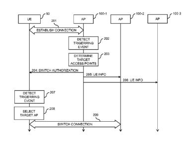
Fig. 2 further illustrates the above concepts by referring to an exemplary
procedure of
switching the connection of the UE 50 from the current serving access point
100-1 to another
access point 100-2.
In the procedure of Fig. 2, the connection between the UE 50 and the wireless
communication network is established at step 201. As illustrated, the
connection is
established by setting up a radio link between the UE 50 and the access point
100-1. The
access point 100-1 thus becomes the serving access point for the UE 50.
At step 202, the access point 100-1 detects a triggering event. The triggering
event may for
example correspond to the establishment of the connection at step 201.
Further, the
triggering event may be based on certain measurements and/or evaluations
performed by
the access point 100-1. For example, the access point 100-1 could measure and
evaluate
the quality of the radio link between the UE 50 and the access point 100-1,
e.g., in terms of a
channel quality indicator, beacon power level, or achievable bitrate. The
triggering event
could then correspond to the quality of the radio link being below a given
threshold value.
Further, the access point 100-1 could determine a probability of a failure of
the radio link
between the UE 50 and the access point 100-1. For example, this could be
accomplished on
the basis of statistical information on radio coverage holes in a radio
coverage area of the
CA 02933323 2016-07-29
WO 2015/113305 PCT/CN2014/071844
- 8 -
access point 100-1 and on information on the position or movement of the UE
50. Further,
the access point 100-1 could measure a velocity of the UE 50, e.g., by
evaluating radio
signals transmitted by the UE 50, and the triggering event could correspond to
the velocity of
the UE 50 exceeding a given threshold value. In this case, it can be taken
into account that a
fast moving UE is more likely to require switching to another access point
than a slowly
moving or static UE. Further, the access point 100-1 may evaluate whether a
switching
authorization message which was previously sent to the UE 50 is still valid or
outdated and
trigger sending the switching authorization message when the previously sent
switching
authorization message is no longer valid. This may for example be accomplished
by
providing a timer which is reset each time when the access point 100-1 sends a
new
switching authorization message to the UE 50 and using expiry of the timer as
the triggering
event.
At step 203, the access point 100-1 determines a plurality of target access
points which
constitute candidates to which the connection between the UE 50 and the
wireless
communication network may be switched. In the illustrated exemplary procedure,
it is
assumed that these target access points are the access points 100-2 and 100-3.
The access
point 100-1 may apply various criteria for determining the target access
points 100-2, 100-3.
For example, the access point 100-1 may select access points which are located
in a moving
.. direction of the UE 50 or access points which provide radio coverage in
radio known
coverage holes in the coverage area of the access point 100-1.
The access point 100-1 then sends the switching authorization message 204 to
the UE 50.
This may be accomplished over a control channel supported by the radio link
between the
UE 50 and the access point 100-1. The switching authorization message
indicates the target
access points 100-2, 100-3 determined at step 203. Further, the switching
authorization
message 204 authorizes the UE 50 to autonomously switch the ongoing connection
to one or
more of the target access points 100-2, 100-3 indicated in the switching
authorization
message 204, without requiring further interaction between the UE 50 and the
access point
100-1.
The switching authorization message 204 may carry various kinds of information
which may
be used by the UE 50 for performing the autonomous switching of the
connection. For
example, the switching authorization message 204 may indicate one or more
conditions for
triggering the switching at the UE 50. Such condition may for example
correspond to
measurements performed by the UE 50 indicating that the expected radio link
quality of one
of the target access points 100-2, 100-3 exceeds the radio link quality of the
current serving
CA 02933323 2016-07-29
WO 2015/113305 PCT/CN2014/071844
- 9 -
access point 100-1 by a given amount. Further, such condition may correspond
to
measurements performed by the UE 50 indicating that the radio link quality of
the current
serving access point 100-1 is below a first threshold and the expected radio
link quality of
one of the target access points 100-2, 100-3 is above a second threshold. As a
further
example, such condition may correspond to a failure of the radio link to the
current serving
access point 100-1 or interruption of the connection.
Further, the switching authorization message 204 may indicate information
concerning each
of the indicated target access points 100-2, 100-3. For example, such
information may
include an identity of the target access point 100-2, 100-3, e.g., in terms of
an index. Further,
such information may include a sequence, timing, and/or radio resources used
for a beacon
or pilot signal transmitted by the target access point 100-2, 100-3. Further,
information
concerning communication protocols used by the target access point may be
included. Such
protocol information may in particular be useful if the access points 100-1,
100-2, 100-2, 100-
3, 100-4, differ with respect to the utilized radio access technology.
Further, such information
may include a radio resource mapping of a control channel of the target access
point 100-2,
100-3. Further, such information may indicate the radio access technology used
by the target
access point 100-2, 100-3. Further, such information may include system
information for
accessing the target access point 100-2, 100-3, e.g., in the form of a random
access
preamble or in terms of a cell-specific temporary identifier (e.g., a C-RNTI)
to be used by the
UE 50.
Still further, the switching authorization message 204 may include information
to be applied
by the UE 50 for selecting between the different target access points 100-2,
100-3 indicated
in the switching authorization message 204, e.g., in the form of a priority
order or selection
policy.
The switching authorization message 204 may be valid for a given time period.
Such time
period may be preconfigured in the UE 50 and the access points 100-1, 100-2,
100-3, 100-4
of the wireless communication network. Further, such time period may be
dynamically set for
each switching authorization message. In the illustrated exemplary procedure,
the access
point 100-1 could set the time period before sending the switching
authorization message
204 and indicate the time period in the switching authorization message 204.
The UE 50 is
then authorized to autonomously perform the switching while the time period
has not yet
expired. Expiry of the time period may be monitored by providing a
corresponding timer in
the UE 50. The access point 100-1 may set the time period for example
depending on the
current velocity of the UE 50. For example, if the UE 50 is moving at high
velocity, a shorter
CA 02933323 2016-07-29
WO 2015/113305 PCT/CN2014/071844
- 10 -
time period may be suitable. In certain cases, the switching authorization
message 204 could
also be valid until a specified event, e.g., receipt of a new switching
authorization message or
release of the connection between the UE 50 and the wireless communication
network. In
certain scenarios, the switching authorization message 204 may override a
previously sent
.. switching authorization message or may be overridden by a later sent
switching authorization
message.
In addition to sending the switching authorization message 204, the access
point 100-1 also
provides information concerning the UE 50 to the target access points 100-2,
100-3
determined at step 203, as illustrated by messages 205 and 206. Such
information may for
example include a context of the UE 50 as provided for maintaining the
connection between
the UE 50 and the wireless communication network. In addition, the access
point 100-1 may
also start forwarding user plane data destined to the UE 50 to the target
access points 100-2,
100-3. In this way, the target access points 100-2, 100-3 may be prepared to
immediately
continue serving the UE 50 after switching the connection. The information
provided to the
target access points 100-2, 100-3 may also indicate the validity time period
of the switching
authorization message 204. Here, it may be beneficial to indicate a validity
time period to the
target access points which is larger than the validity time period applied by
the UE 50,
thereby ensuring that the target access points 100-2, 100-3 are prepared also
in cases
where the UE 50 attempts switching of the connection at the very end of the
validity time
period indicated to the UE 50. If the access point 100-1 has determined a
priority order of the
target access points 100-2, 100-3, the access point 100-1 may send the
information to the
different target access points 100-2, 100-3 in the order of decreasing
priority.
Upon receiving the switching authorization message 204, the UE 50 may start
monitoring
procedures with respect to the target access points 100-2, 100-3 indicated in
the switching
authorization message 204. For example, the UE 50 may perform measurements to
determine which of the indicated target access points 100-2, 100-3 provides
the highest
expected radio link quality. After such determination, the UE 50 may continue
monitoring only
.. the target access point 100-2, 100-3 with the highest expected radio link
quality. In other
scenarios, the UE 50 may continue to monitor all the indicated target access
points 100-2,
100-3. The monitoring may use information provided in the switching
authorization message
204, e.g., sequence, timing, and/or radio resources used for a beacon or pilot
signal
transmitted by the target access point 100-2, 100-3.
However, the UE 50 performs no immediate switching of the connection. Rather,
the UE 50
performs switching of the connection action only in response to detecting a
triggering event,
CA 02933323 2016-07-29
WO 2015/113305 PCT/CN2014/071844
- 11 -
as illustrated by step 207. Such triggering event may be preconfigured in the
UE 50 or may
be indicated in the switching authorization message 204. For example, the
triggering event
may correspond to a failure of the radio link between the UE 50 and the
current serving
access point 100-1. Further, such triggering event may correspond to
measurements
performed by the UE 50 indicating that the expected radio link quality of one
of the target
access points 100-2, 100-3 exceeds the radio link quality of the current
serving access point
100-1 by a given amount. Further, such triggering event may correspond to
measurements
performed by the UE 50 indicating that the radio link quality of the current
serving access
point 100-1 is below a first threshold and the expected radio link quality of
one of the target
access points 100-2, 100-3 is above a second threshold.
In response to detecting the triggering event at step 207, the UE 50 initiates
switching of the
connection to one of the target access points 100-2, 100-3 indicated in the
switching
authorization message 204. For this purpose, the UE 50 may also select between
the
indicated target access points 100-2, 100-3, as indicated by step 208. For
example, the UE
50 may select the target access point 100-2, 100-3 which provides the highest
expected
radio link quality. In the illustrated exemplary procedure, it is assumed that
the UE 50 selects
the target access point 100-2. As illustrated by step 209, the UE 50 then
performs the
switching of the connection by setting up a new radio link to the target
access point 100-2
selected at step 208, which then becomes the new serving access point for the
UE 50.
Fig. 3 illustrates a further exemplary procedure of switching the connection
of the UE 50 from
the current serving access point 100-1 to another access point 100-2. The
procedure of Fig.
3 is in many aspects similar to that of Fig. 2. However, in the procedure of
Fig. 3 a different
process is used for providing the target access point 100-2 with information
concerning the
UE 50.
In the procedure of Fig. 3, the connection between the UE 50 and the wireless
communication network is established at step 301. As illustrated, the
connection is
established by setting up a radio link between the UE 50 and the access point
100-1. The
access point 100-1 thus becomes the serving access point for the UE 50.
At step 302, the access point 100-1 detects a triggering event. The triggering
event may for
example correspond to the establishment of the connection at step 301.
Further, the
triggering event may be based on certain measurements and/or evaluations
performed by
the access point 100-1. For example, the access point 100-1 could measure and
evaluate
the quality of the radio link between the UE 50 and the access point 100-1,
e.g., in terms of a
CA 02933323 2016-07-29
WO 2015/113305 PCT/CN2014/071844
- 12 -
channel quality indicator, beacon power level, or achievable bitrate. The
triggering event
could then correspond to the quality of the radio link being below a given
threshold value.
Further, the access point 100-1 could determine a probability of a failure of
the radio link
between the UE 50 and the access point 100-1. For example, this could be
accomplished on
the basis of statistical information on radio coverage holes in a radio
coverage area of the
access point 100-1 and on information on the position or movement of the UE
50. Further,
the access point 100-1 could measure a velocity of the UE 50, e.g., by
evaluating radio
signals transmitted by the UE 50, and the triggering event could correspond to
the velocity of
the UE 50 exceeding a given threshold value. In this case, it can be taken
into account that a
fast moving UE is more likely to require switching to another access point
than a slowly
moving or static UE. Further, the access point 100-1 may evaluate whether a
switching
authorization message which was previously sent to the UE 50 is still valid or
outdated and
trigger sending the switching authorization message when the previously sent
switching
authorization message is no longer valid. This may for example be accomplished
by
providing a timer which is reset each time when the access point 100-1 sends a
new
switching authorization message to the UE 50 and using expiry of the timer as
the triggering
event.
At step 303, the access point 100-1 determines a plurality of target access
points which
constitute candidates to which the connection between the UE 50 and the
wireless
communication network may be switched. In the illustrated exemplary procedure,
it is
assumed that these target access points are the access points 100-2 and 100-3.
The access
point 100-1 may apply various criteria for determining the target access
points 100-2, 100-3.
For example, the access point 100-1 may select access points which are located
in a moving
direction of the UE 50 or access points which provide radio coverage in radio
known
coverage holes in the coverage area of the access point 100-1.
The access point 100-1 then sends the switching authorization message 304 to
the UE 50.
This may be accomplished over a control channel supported by the radio link
between the
UE 50 and the access point 100-1. The switching authorization message 304
indicates the
target access points 100-2, 100-3 determined at step 303. Further, the
switching
authorization message 304 authorizes the UE 50 to autonomously switch the
ongoing
connection to one or more of the target access points 100-2, 100-3 indicated
in the switching
authorization message 304, without requiring further interaction between the
UE 50 and the
access point 100-1.
CA 02933323 2016-07-29
WO 2015/113305 PCT/CN2014/071844
- 13 -
The switching authorization message 304 may carry various kinds of information
which may
be used by the UE 50 for performing the autonomous switching of the
connection. For
example, the switching authorization message 304 may indicate one or more
conditions for
triggering the switching at the UE 50. Such condition may for example
correspond to
measurements performed by the UE 50 indicating that the expected radio link
quality of one
of the target access points 100-2, 100-3 exceeds the radio link quality of the
current serving
access point 100-1 by a given amount. Further, such condition may correspond
to
measurements performed by the UE 50 indicating that the radio link quality of
the current
serving access point 100-1 is below a first threshold and the expected radio
link quality of
one of the target access points 100-2, 100-3 is above a second threshold. As a
further
example, such condition may correspond to a failure of the radio link to the
current serving
access point 100-1 or an interruption of the connection.
Further, the switching authorization message 304 may indicate information
concerning each
of the indicated target access points 100-2, 100-3. For example, such
information may
include an identity of the target access point 100-2, 100-3, e.g., in terms of
an index. Further,
such information may include a sequence, timing, and/or radio resources used
for a beacon
or pilot signal transmitted by the target access point 100-2, 100-3. Further,
information
concerning communication protocols used by the target access point 100-2, 100-
3 may be
included. Such protocol information may in particular be useful if the access
points 100-1,
100-2, 100-2, 100-3, 100-4 differ with respect to the utilized radio access
technology. Further,
such information may include a radio resource mapping of a control channel of
the target
access point 100-2, 100-3. Further, such information may indicate the radio
access
technology used by the target access point 100-2, 100-3. Further, such
information may
include system information for accessing the target access point 100-2, 100-3,
e.g., in the
form of a random access preamble or in terms of a cell-specific temporary
identifier (e.g., a
C-RNTI) to be used by the UE 50.
Still further, the switching authorization message 304 may include information
to be applied
by the UE 50 for selecting between the different target access points 100-2,
100-3 indicated
in the switching authorization message 304, e.g., in the form of a priority
order or selection
policy.
The switching authorization message 304 may be valid for a given time period.
Such time
period may be preconfigured in the UE 50 and the access points 100-1, 100-2,
100-3, 100-4,
100-5 of the wireless communication network. Further, such time period may be
dynamically
set for each switching authorization message. In the illustrated exemplary
procedure, the
CA 02933323 2016-07-29
WO 2015/113305 PCT/CN2014/071844
- 14 -
access point 100-1 could set the time period before sending the switching
authorization
message 304 and indicate the time period in the switching authorization
message 304. The
UE 50 is then authorized to autonomously perform the switching while the time
period has
not yet expired. Expiry of the time period may be monitored by providing a
corresponding
timer in the UE 50. The access point 100-1 may set the time period for example
depending
on the current velocity of the UE 50. For example, if the UE 50 is moving at
high velocity, a
shorter time period may be suitable. In certain cases, the switching
authorization message
304 could also be valid until a specified event, e.g., receipt of a new
switching authorization
message or release of the connection between the UE 50 and the wireless
communication
network. In certain scenarios, the switching authorization message 304 may
override a
previously sent switching authorization message or may be overridden by a
later sent
switching authorization message.
Upon receiving the switching authorization message 304, the UE 50 may start
monitoring
procedures with respect to the target access points 100-2, 100-3 indicated in
the switching
authorization message 304. For example, the UE 50 may perform measurements to
determine which of the indicated target access points 100-2, 100-3 provides
the highest
expected radio link quality. After such determination, the UE 50 may continue
monitoring only
the target access point 100-2, 100-3 with the highest expected radio link
quality. In other
scenarios, the UE 50 may continue to monitor all the indicated target access
points 100-2,
100-3. The monitoring may use information provided in the switching
authorization message
304, e.g., sequence, timing, and/or radio resources used for a beacon or pilot
signal
transmitted by the target access point 100-2, 100-3.
However, the UE 50 performs no immediate switching of the connection. Rather,
the UE 50
performs switching of the connection action only in response to detecting a
triggering event,
as illustrated by step 305. Such triggering event may be preconfigured in the
UE 50 or may
be indicated in the switching authorization message 304. For example, the
triggering event
may correspond to a failure of the radio link between the UE 50 and the
current serving
access point 100-1. Further, such triggering event may correspond to
measurements
performed by the UE 50 indicating that the expected radio link quality of one
of the target
access points 100-2, 100-3 exceeds the radio link quality of the current
serving access point
100-1 by a given amount. Further, such triggering event may correspond to
measurements
performed by the UE 50 indicating that the radio link quality of the current
serving access
point 100-1 is below a first threshold and the expected radio link quality of
one of the target
access points 100-2, 100-3 is above a second threshold.
CA 02933323 2016-07-29
WO 2015/113305 PCT/CN2014/071844
- 15 -
In response to detecting the triggering event at step 305, the UE 50 initiates
switching of the
connection to one of the target access points 100-2, 100-3 indicated in the
switching
authorization message 304. For this purpose, the UE 50 may also select between
the
indicated target access points 100-2, 100-3, as indicated by step 306. For
example, the UE
50 may select the target access point 100-2, 100-3 which provides the highest
expected
radio link quality. In the illustrated exemplary procedure, it is assumed that
the UE 50 selects
the target access point 100-2. As illustrated by step 307, the UE 50 then
performs the
switching of the connection by setting up a new radio link to the target
access point 100-2
selected at step 306, which then becomes the new serving access point for the
UE 50.
When switching the connection at step 307, the UE 50 also indicates an
identity of the
previous serving access point 100-1, e.g., in terms of an index, to the new
serving access
point 100-2. The new serving access point 100-2 may then use this identity to
send a request
308 for information concerning the UE 50 to the previous serving access point
100-1.
In response to the request 308, the access point 100-1 provides information
concerning the
UE 50 to the new serving access point 100-2, as illustrated by message 309.
Such
information may for example include a context of the UE 50 as provided for
maintaining the
connection between the UE 50 and the wireless communication network.
The connection switching procedures as explained above may also be used
together with
other kinds of connection switching procedures, e.g., a connection switching
procedure in
which the UE 50 is instructed by the current serving access point to
immediately switch to a
certain target access point. In such cases, the autonomous switching procedure
could be
used as a backup for cases where an instruction for immediate switching is not
possible, e.g.,
due to a failure of the radio link between the UE 50 and the current serving
access point.
Accordingly, if the UE 50 first receives the switching authorization message
and then a
command for immediate switching of the connection, the UE 50 may first attempt
to perform
the immediate switching and, if this immediate switching fails, continue with
the autonomous
switching procedure.
Fig. 4 shows a flowchart for illustrating a method which may be used for
implementing the
above concepts in an access node of a wireless communication network, e.g., in
one of the
access nodes 100-1, 100-2, 100-3, 100-4. If a processor based implementation
of the access
point is used, the steps of the method may be performed by one or more
processors of the
access point. For this purpose, the processor(s) may execute correspondingly
configured
CA 02933323 2016-07-29
WO 2015/113305 PCT/CN2014/071844
- 16 -
program code. Further, at least some of the corresponding functionalities may
be hardwired
in the processor(s).
At step 410, the access point serves a connection between a UE, e.g., the UE
50, and the
wireless communication network. The connection is based on a radio link
between the UE
and the access point. In some scenarios, the connection may further be based
on additional
radio links between the UE and other access points.
At step 420, the access point detects a triggering event. Various kinds of
triggering events
may be used. For example, the access point may send the message in response to
establishing the connection between the UE and the communication network.
Further, the
access point may determine a failure probability of a radio link between the
UE and the
access point and send the message in response to the failure probability being
above a
threshold. Further, the access point may measure a quality of a radio link
between the user
equipment and the access point and send the message in response to the quality
of the radio
link being below a threshold. Further, the access point may measure a velocity
of the UE and
send the message in response to the velocity being above a threshold. Further,
the access
point may send the message in response to determining that a further plurality
of target
access points, which was previously indicated to the user equipment, is no
longer valid. In
the exemplary procedures of Figs. 2 and 3 this is accomplished by considering
the validity
time period of the switching authorization message.
At step 430, the access point determines a plurality of target access points.
This
determination may for example be based on measurements performed by the access
point.
At step 440, the access point sends a message to the UE. The message indicates
the target
access points determined at step 430 and authorizes the UE to autonomously
switch the
connection to one or more of the target access points. As explained above,
this autonomous
switching does not require further interaction between the UE and the access
point. The
above-mentioned switching authorization messages 204 and 304 are examples of
such
message.
The message may further indicate a condition to be evaluated by the UE for
triggering the
switching to said one or more of the target access points. For example, such
condition may
be based on measurements performed by the UE, e.g., to determine a radio link
qualities.
For example, the switching may be triggered when a radio link quality expected
for one of the
target access points exceeds a radio link quality of the access point by a
given amount.
CA 02933323 2016-07-29
WO 2015/113305 PCT/CN2014/071844
- 17 -
Further, the switching may be triggered when a radio link quality expected for
one of the
target access points is above a first threshold and a radio link quality of
the access point is
below a second threshold. Further, the switching may be triggered if a radio
link between the
UE and the access point fails.
For each of the target access points, the message may further indicate
information to be
used by the UE for connecting to this target access point. For example, this
may include a
information on radio configuration, access parameters, radio resources, a cell-
specific
temporary identifier to be used by the UE, or the like. Further, the message
may indicate a
priority order of the target access points.
Further, the access point may send, to each of the plurality of target access
points,
information related to the UE. This information may be used by the target
access points to
prepare for a potential switching of the connection. As explained above, this
information may
in particular include a context of the UE, as used for maintaining the ongoing
connection
between the UE and the wireless communication network. As an alternative, the
access point
may also send such information after switching of the connection to one or
more of the
plurality of target access points. In such cases, the access point may receive
a request from
the target access point to which the connection was switched and send the
information
related to the UE in response to the request to this target access point.
Fig. 5 shows a flowchart for illustrating a method which may be used for
implementing the
above concepts in a UE, e.g., in the UE 50. If a processor based
implementation of the UE is
used, the steps of the method may be performed by one or more processors of
the UE. For
this purpose, the processor(s) may execute correspondingly configured program
code.
Further, at least some of the corresponding functionalities may be hardwired
in the
processor(s).
At step 510, establishes a connection to a wireless communication network,
e.g., a wireless
communication network using a deployment as explained in connection with Fig.
1. The
connection is based on a radio link between the UE and an access point of the
wireless
communication network. In some scenarios, the connection may further be based
on
additional radio links between the UE and other access points.
At step 520, the UE receives a message from the access point which currently
serves the
connection. The message indicates a plurality of target access points and
authorizes the UE
to autonomously switch the connection to one or more of the target access
points. As
CA 02933323 2016-07-29
WO 2015/113305 PCT/CN2014/071844
- 18 -
explained above, this autonomous switching does not require further
interaction between the
UE and the access point. The above-mentioned switching authorization messages
204 and
304 are examples of such message. In some scenarios, the UE may receive the
message in
response to establishing the connection between the UE and the communication
network.
For each of the target access points, the message may further indicate
information to be
used by the UE for connecting to this target access point. For example, this
may include a
information on radio configuration, access parameters, radio resources, a cell-
specific
temporary identifier to be used by the UE, or the like. Further, the message
may indicate a
priority order of the target access points.
At step 530, the UE determines whether a triggering event occurred. If a
triggering event
occurred, the method continues with steps 540 and 550, as indicated by branch
"Y". If no
triggering event occurred, the method continues with step 560, as indicated by
branch "N".
The triggering event may be based on a quality of a radio link between the UE
and the target
access points indicated in the message, as measured by the UE. The triggering
event may
also be based on a quality of a radio link between the UE and the access
point, as measured
by the UE. For example, the triggering event may correspond to a radio link
quality expected
for one of the target access points exceeding a radio link quality of the
access point by a
given amount. Further, the triggering event may correspond to a radio link
quality expected
for one of the target access points being above a first threshold and a radio
link quality of the
access point being below a second threshold. Further, the triggering event may
correspond
to failure of a radio link between the UE and the access point or interruption
of the
connection. The message of step 520 may also indicate a condition to be
evaluated by the
UE for triggering the switching to the target access point(s) and the
triggering event may be
based on said indicated condition.
At step 540, the UE may select one or more target access points from the
plurality of target
access points indicated in the message of step 520. This may be accomplished
on the basis
of information indicated in the message of step 520. For example, the message
may indicate,
a priority order of the target access points, and the UE may determine select
the target
access points depending on the indicated priority order. Alternatively, also
more complex
selection policies may be applied by the UE and may also be indicated in the
message, e.g.,
selection policies which are based on measurements performed by the UE.
CA 02933323 2016-07-29
WO 2015/113305 PCT/CN2014/071844
- 19 -
At step 550, the UE switches the connection to the target access point(s)
selected at step
540. This may be accomplished on the basis of information indicated in the
message of step
520. In particular, the message may indicate, for each of the indicated target
access points,
information to be used by the UE for connecting to this target access point,
and the UE may
performs the switching on the basis of this indicated information. In some
scenarios, after
switching to the target access point, the UE may also indicate information
related to the
access point, e.g., an identity of the access point, to this target access
point. If this target
access point becomes the new serving access point for the UE, it may use this
information
for obtaining information related to the UE from the previous serving access
point.
At step 560, if no triggering event was detected at step 530, the UE may keep
the current
access point(s) for maintaining the connection.
It is to understood that the methods of Figs. 4 and 5 may be used in
combination, e.g., in a
system formed of a UE, which operates according to the method of Fig. 5, and
an access
point currently serving the UE, which operates according to the method of Fig.
4.
Fig. 6 illustrates exemplary structures of an access point for a wireless
communication
network which may be used to implement the above concepts. For example, the
illustrated
structures may be used to implement the above-described functionalities of the
access point
100-1 which currently serves the connection between the UE 50 and the wireless
communication network.
In the illustrated example, the access point includes a radio interface 610
which may be used
.. for serving a connection between the wireless communication network and a
UE. Further, the
access point may include a backhaul interface 620 which may be used for
communication
with other nodes of the wireless communication network, e.g., other access
points or
gateway nodes.
Further, the access point includes one or more processor(s) 650 coupled to the
interfaces
610 and 620, and a memory 660 coupled to the processor(s) 650. The memory 660
may
include a read-only memory (ROM), e.g., a flash ROM, a RAM, e.g., a dynamic
RAM (DRAM)
or static RAM (SRAM), a mass storage, e.g., a hard disk or solid state disk,
or the like. The
memory 660 includes suitably configured program code modules to be executed by
the
processor(s) 650 so as to implement the functionalities as described in
connection with the
method of Fig. 4, in particular functionalities as explained above for the
access node 100-1.
More specifically, the program code modules in the memory 660 may include a
CA 02933323 2016-07-29
WO 2015/113305 PCT/CN2014/071844
- 20 -
measurement module 670 so as to implement the above-described functionalities
of
performing measurements for triggering the sending of the switching
authorization message
or for determining the target access points indicated in the switching
authorization message.
Further, the program code modules in the memory 660 may include a connection
management module 680 so as to implement the above-mentioned functionalities
of serving
a the connection between the UE and the wireless communication network,
selecting target
access points or handling communication with such target access points, and
sending the
switching authorization message. Still further, the memory 660 may include a
control module
690 so as to implement general control functionalities, such as control of the
radio interface,
processing messages, controlling forwarding of data, or the like.
It is to be understood that the structures as illustrated in Fig. 6 are merely
schematic and that
the access point may actually include further components which, for the sake
of clarity, have
not been illustrated, e.g., further interfaces or further processors. Also, it
is to be understood
that the memory 660 may include further types of program code modules, which
have not
been illustrated, e.g., program code modules for implementing known
functionalities of an
access point. In some implementations, also a computer program may be provided
for
implementing functionalities of the access point, e.g., in the form of a
physical medium
storing the program code modules to be stored in the memory 660 or by making
such
program code available for download.
Fig. 7 illustrates exemplary structures of a UE which may be used to implement
the above
concepts. For example, the illustrated structures may be used to implement the
above-
described functionalities of the UE 50.
In the illustrated example, the UE includes a radio interface 710 which may be
used for
establishing a connection to a wireless communication network.
Further, the UE includes one or more processor(s) 750 coupled to the
interfaces 710 and
720, and a memory 760 coupled to the processor(s) 750. The memory 760 may
include a
ROM, e.g., a flash ROM, a RAM, e.g., a DRAM or SRAM, a mass storage, e.g., a
hard disk
or solid state disk, or the like. The memory 760 includes suitably configured
program code
modules to be executed by the processor(s) 750 so as to implement the
functionalities as
described in connection with the method of Fig. 5, in particular
functionalities as explained
above for the UE 50. More specifically, the program code modules in the memory
760 may
include a measurement module 770 so as to implement the above-described
functionalities
of performing measurements for triggering the switching or selecting a target
access point
CA 02933323 2016-07-29
WO 2015/113305 PCT/CN2014/071844
- 21 -
among multiple candidates. Further, the program code modules in the memory 760
may
include a connection management module 780 so as to implement the above-
mentioned
functionalities of maintaining the connection between the UE and the wireless
communication network, selecting a target access point, and performing the
switching of the
connection as authorized by the switching authorization message. Still
further, the memory
760 may include a control module 790 so as to implement general control
functionalities,
such as control of the radio interface, processing control messages, or the
like.
It is to be understood that the structures as illustrated in Fig. 7 are merely
schematic and that
the UE may actually include further components which, for the sake of clarity,
have not been
illustrated, e.g., further interfaces or further processors. Also, it is to be
understood that the
memory 760 may include further types of program code modules, which have not
been
illustrated, e.g., program code modules for implementing known functionalities
of a UE. In
some implementations, also a computer program may be provided for implementing
functionalities of the UE, e.g., in the form of a physical medium storing the
program code
modules to be stored in the memory 760 or by making such program code
available for
download.
As can be seen, the concepts as described above may be used for efficiently
managing the
connection of the UE to the wireless communication network. In particular, by
authorizing the
UE to autonomously switch the connection to one or more from a plurality of
target access
points, it becomes possible to perform the connection switching even if the
radio link
between the UE and the current serving access point of the UE fails.
It is to be understood that the examples and embodiments as explained above
are merely
illustrative and susceptible to various modifications. For example, the
illustrated concepts
could be used in connection with various types of wireless communication
networks networks,
without limitation to the UDN technology used in the above-described exemplary
implementations. Moreover, it is to be understood that the above concepts may
be
implemented by using correspondingly designed software to be executed by one
or more
processors of an existing device, or by using dedicated device hardware.