Note: Descriptions are shown in the official language in which they were submitted.
CA 02938368 2016-07-28
WO 2015/116557 PCT/US2015/012998
OPTICAL IMAGING ASSEMBLY AND SYSTEM WITH OPTICAL
DISTORTION CORRECTION
TECHNICAL FIELD
[00011 The present disclosure relates generally to optical imaging and
measuring systems, and more specifically to such a system used for calibrating
fluid flow
to a medical infusion pump.
BACKGROUND
[00021 One way to measure the rate of flow of a fluid is to cause the fluid
flow
to be in a continuous stream of drops of known volume, and then count the
number of
droplets per unit time to deduce the flow rate. This approach is very coarse
because it has
a measurement granularity equal to the volume of the droplets, and it assumes
that the
volume of each droplet is the same as it detaches from its orifice. Indeed,
this "drop
counting" approach has measurement accuracy that is inadequate for many
applications,
such as medical infusion. The granularity problem can be eliminated if the
volume of the
droplets can be measured in real-time as the droplets form and detach from.
the supporting
orifice.
[00031 One way to measure the volume is to capture a two-dimensional image
of a pendant drop suspended from its orifice, and then measure its width along
several
points from the tip of the droplet to the orifice. If rotational symmetry is
assumed, the
droplet can be represented as a series of stacked disks where the volume of
each disk is V
= frI-1(Width/2)2, where H is the distance between points along the axis of
rotation. The
volume of the drop is the sum of the volume of all the disks. To obtain good
droplet
volume accuracy, it is important to obtain good estimates of the width of the
droplet. The
rate of fluid flow can then be more accurately determined by measuring the
time rate of
change of droplet volume, by for example, collecting and processing a series
of images in
quick succession, such as a series of video images.
[00041 Complicating the imaging process is the fact that the pendant drop of
an
infusion tube is enclosed in a generally cylindrical drip chamber that
introduces enormous
CA 02938368 2016-07-28
WO 2015/116557 PCT/US2015/012998
amounts of optical distortion in the direction that the width of the droplet
is to be
measured. Further complicating matters is that splashes and condensation can
cause fluid
droplets to form on the inner surface of the drip chamber that can occlude or
partially
occlude the edge of the droplet from the image. Lastly, due to manufacturing,
assembly,
and even usage processes, the imaging assembly must be able to tolerate
changes in
distance between the axis of the pendant droplet and the lens without causing
an
appreciable change in the calculated volume of the droplet.
SUMMARY
[0005] Accordingly, an optical imaging assembly is prescribed that is
optically
fast, corrects for optical distortion introduced by a sleeve co-axial with an
axis of the
object, and is telecentric in object space. The present assembly employs
combinations of
cylindrical or acylindrical, and spherical or aspherical lens elements to
correct optical
distortion and other aberrations. In addition, the present disclosure relates
to an optical
imaging assembly for use with an infusion tube, or, more particularly, for
imaging the
pendant drop within an infusion tube. The present optical imaging assembly
corrects for
the optical distortion caused by the infusion tube, is optically fast so that
droplets and
other artifacts residing on the wall of the infusion tube are out of focus and
not imaged by
the imaging system, and is telecentric so the magnification of the object is
substantially
independent of the distance between the object and the first lens element.
[0006] According to aspects illustrated herein, there is provided an optical
imaging assembly, including: an optical axis connecting an object plane and an
image
plane; an object axis within the object plane and perpendicular to the optical
axis; a first
optical element with a substantially planar input surface and acylindrical
output surface
where the axis of acylindricity intersects the optical axis and is parallel to
the object axis;
a second optical element with a substantially planar input surface and
acylindrical output
surface where the axis of acylindricity intersects the optical axis and is
parallel to the
object axis and the acylindrical output surface of the second optical element
is spaced
away from the acylindrical output surface of the first optical element; a
third optical
element with input and output surfaces having rotational symmetry and centered
on the
2
optical axis; an aperture stop; and a fourth optical element with input and
output surfaces
having rotational symmetry and centered on the optical axis.
[0007] More specifically, an optical imaging assembly is provided, including
an
optical axis, with an object axis, having a light-transmissive sleeve
enclosing the object
axis, telecentric in object space, having at least three refractive lens
elements, in two of
the lens elements, at least one of said elements having surfaces with at least
one of
cylindrical and acylindrical prescription, with an image plane, wherein the
object being
imaged lies within the sleeve.
[0008] In one embodiment, an assembly includes four lens elements arranged in
a manner such that the resulting optical imaging assembly is able to correct
for large
amounts of optical distortion, is telecentric in object space, has an f-number
of 1.5 or less.
Two of the lens elements have aspherical prescriptions, and the other two lens
elements
have acylindrical surfaces, wherein the two acylindrical surfaces are
Separated from one
another. The optical imaging assembly is well adapted for use in a liquid
flowmeter
system in which the fluid flows in a series of droplets enclosed in a drip
chamber.
[0009] In another embodiment, an imaging assembly is configured for removing
optical distortion from an image generated by an object located within a light
transmissive sleeve. The assembly includes a first optical element acting in
conjunction
with a second optical element; both optical elements have cylindrical and/or
acylindrical
.. surfaces that together remove optical distortion from the image.
[0009a] According to aspects illustrated herein, there is provided an optical
imaging assembly, comprising: an optical axis; an object axis defined.by an
object being
imaged; an aperture stop disposed on the optical axis; a light-transmissive
sleeve
enclosing the object axis, being telecentric in object space, such that a ray
leaving the
object travels in a direction substantially parallel to the optical axis, and
passes
substantially through a center of the aperture stop; and at least three
refractive lens
elements being arranged between the object and the aperture stop without any
other
intervening optical component, at least one of said refractive lens elements
having
surfaces having at least one of cylindrical and acylindrical prescription,
with an image
.. plane, wherein the object being imaged lies within the sleeve.
3
CA 2938368 2020-01-23
[0009b] According to aspects illustrated herein, there is provided an imaging
assembly, comprising: an optical axis; an object axis defined by an object
being imaged;
an aperture stop disposed on the optical axis; four lens elements disposed on
the optical
axis, at least three of said four lens elements being arranged between the
object and the
aperture stop without any other intervening optical component; and a light-
transmissive
sleeve being telecentric in object space, such that a ray leaving the object
travels in a
direction substantially parallel to the optical axis, and passes substantially
through a
center of the aperture stop, wherein the imaging assembly has an optical speed
f-number
of 1.5 or less, wherein two of said four lens elements have aspherical
prescriptions, and
the other two of said four lens elements have acylindrical surfaces, and
wherein said two
acylindrical surfaces are separated from one another.
10009c1 According to aspects illustrated herein, there is provided an imaging
assembly configured for removing optical distortion from an image generated by
an
object located within a transparent sleeve, said imaging assembly comprising:
a first
optical element having a first input surface and a first output surface, said
first input
surface having a substantially planar surface, and said first output surface
having a
cylindrical or acylindrical surface; and a second optical element having a
second input
surface and a second output surface, said second input surface having the
substantially
planar surface, said second output surface having the cylindrical or
acylindrical surface,
wherein both said first and second optical elements are arranged without any
other
intervening optical component such that said first and second output surfaces
acting in
conjunction remove the optical distortion from the image generated by the
object.
BRIEF DESCRIPTION OF THE DRAWINGS
[0010] The nature and mode of operation of the present optical imaging
assembly will now be more fully described in the following detailed
description taken
with the accompanying drawing figures, in which:
[0011] Figure 1 is a schematic top-view of the present optical imaging
assembly;
3a
CA 2938368 2020-01-23
CA 02938368 2016-07-28
WO 2015/116557 PCT/US2015/012998
[0012] Figure 2 is a schematic side-view of the present optical imaging
assembly;
100131 Figure 3 is an isometric view of the object, the sleeve about the
object,
and objective lens elements of the present optical imaging assembly;
[0014] Figure 4 is a top-view ray-trace plot showing how a fan of rays
originating at the edge of the field in the object plane propagate through the
optical
imaging assembly to the image plane;
[0015] Figure 5 is a representative image of a pendant drop within a sleeve
having inner surface droplets in which the optical imaging assembly is not
optically fast;
[0016] Figure 6 is a representative image of a pendant drop within a sleeve
having inner surface droplets in which the optical imaging assembly is
optically fast;
[0017] Figures 7A, 7B, and 7C, are a prescription of an embodiment of the
present optical imaging assembly, created by the Zem.ax lens design program.;
[0018] Figures 8A and 8B are graphs from the Zemax lens design program
illustrating the amount of optical distortion of the optical imaging assembly
in the
directions parallel to the object axis and perpendicular to the object axis,
respectively,
with a cylindrical sleeve located about the object;
[0019] Figure 9 are spot diagrams from the Zemax lens design program showing
the size and shape of the images produced by the present optical imaging
assembly in
which the object consists of delta-functions at six field locations with a
sleeve located
about the object; and
[0020] Figure 10 is a block diagram illustrating how the present optical
imaging
assembly is used in a flow-rate measurement system.
4
CA 02938368 2016-07-28
WO 2015/116557 PCT/US2015/012998
DETAILED DESCRIPTION
[0021] At the outset, it should be appreciated that like drawing numbers on
different views identify identical, or functionally similar, elements of the
present
disclosure.
[0022] Furthermore, it is understood that the present disclosure is not
limited to
the particular methodology, materials, and modifications as described, and any
of these
may, of course, vary. It is also understood that the terminology used herein
is for the
purpose of describing particular aspects only, and is not intended to limit
the scope of the
present disclosure, which is limited only by the appended claims.
[0023] Unless defined otherwise, all technical and scientific terms used
herein
have the same meaning as commonly understood to one of ordinary skill in the
art to
which the present disclosure belongs. Although any methods, devices, or
materials
similar or equivalent to those described herein can be used in the practice or
testing of the
present disclosure, example methods, devices, and, materials are now
described.
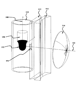
[0024] Figure 1 is a schematic top-view of optical imaging assembly 100, which
includes an optical axis 102, a first lens element 112 having an input surface
134 and an
output surface 136, a second lens element 114 having an input surface 138 and
an output
surface 140, a third lens element 116 having an input surface 142 and an
output surface
144, an aperture stop 118, and a fourth lens element 120 having an input
surface 146 and
an output surface 148. The object plane 104 is perpendicular to the optical
axis 102 and
contains at least a portion of the object being imaged such as the pendant
drop 152 shown
in Figure 3. Object space 101 also includes a sleeve 110 having an axis of
rotation 108,
the axis of rotation 108 also being substantially coinciden.t with a
rotationally symmetric
object such as the pendant drop 152 shown in Figure 3. The sleeve 110 is
preferably
substantially cylindrical, is contemplated as being slightly cone-shaped with
a slope of
approximately 0.5 to 5.0 for facilitating the molding process, and has an
inner surface
130 and an outer surface 132. The image produced by the optical imaging
assembly 100
lies in image plane 106.
5
CA 02938368 2016-07-28
WO 2015/116557 PCT/US2015/012998
[00251 Also shown in Figure 1 is a key to the axes in which the Z-axis is
taken
to be the optical axis 102, the Y-axis is perpendicular to the Z-axis in the
plane of the
drawing, and the X-axis is perpendicular to the Z-axis and perpendicular to
the plane of
the drawing. The object plane 104 is in the X-Y plane at Z=0.
[00261 Each of the components listed above will be described more fully with
reference to Figures 1, 2, and 3. The first lens element 112 is a refractive
optical element
having a substantially planar input surface 134 and a cylindrical or
acylindrical output
surface 136. Planar surfaces are less costly to produce than non-planar
surfaces, and
should be used whenever possible to reduce the manufacturing costs of the
optical
imaging assembly 100. Furthermore, making input surface 134 planar facilitates
placement and replacement of the sleeve 110 in front of the optical imaging
assembly 100
so that different objects can be installed in front of the optical imaging
assembly 100 as
needed. Output surface 136, being cylindrical or acylindrical, has optical
power in the Y-
axis direction and little or no optical power in the X-axis.
[00271 The second lens element 114 is a refractive optical element having a
substantially planar input surface 138 and a cylindrical or acylindrical
output surface 140.
Planar surfaces are less costly to produce than non-planar surfaces, and
should be used
whenever possible to reduce the manufacturing costs of the optical imaging
assembly
100. The output surface 140, being cylindrical or acylindrical, has optical
power in the
Y-axis direction and little or no optical power in the X-axis.
[00281 In Figures 1, 2, and 3, the cylindrical / acylindrical surfaces are
shown to
reside on the output surfaces, 136 and 140, although they could reside on the
input
surfaces, 134 and 138, or a combination of input and output surfaces such as
input
surfaces 134 and output surface 140 or output surface 136 and input surface
138.
[00291 In Figures 1, 2, and 3, both cylindrical / acylindrical surfaces have
optical power in the Y-direction (i.e., perpendicular to the optical axis 102
and
perpendicular to the object axis 108), although the optical power could
instead be in the
X-direction (Le., the direction parallel to the object axis 108), or one
cylindrical /
6
CA 02938368 2016-07-28
WO 2015/116557 PCT/US2015/012998
acylindrical surface can have optical power in the Y-direction and the other
cylindrical /
acylindrical surface can have optical power in the X-direction.
100301 The third lens element 116 is a refractive optical element having a
spherical or aspherical input surface 142 whose center of rotation is
substantially
coincident with the optical axis 102. Similarly, the output surface 144 is
spherical or
aspherical and also has a center of rotation substantially coincident with the
optical axis
102.
[0031] An aperture stop 118 is placed between the third lens element 116 and
the fourth lens element 120. The aperture stop 118 can be fabricated from
opaque thin
sheet material, such as metal or plastic sheeting. The aperture of the
aperture stop 118 is
nominally round, but can have other shapes as well such as square,
rectangular,
hexagonal, octagonal, or any shape made from arbitrary lines segments and
arcs. The
aperture of the aperture stop 118 is nominally centered on the optical axis
102. A
distance from one side to an opposing side of the aperture of the aperture
stop 118 can be
between lmm and 100mm when measured through the optical axis 102.
[0032] All refractive lens elements 112, 114, 116, and 118 are contemplated as
being made from glass or polymer such as acrylic, polycarbonate, or
polystyrene,
although in general materials having a higher refractive index such as
polycarbon ate or
polystyrene provide for greater optical power, which in turn facilitates a
more compact
design in which the distance from the object plane 104 to the image plane 106
is reduced.
If the choice of material is polymer, any or all of the lens elements 112,
114, 116, and 118
can be made from an injection molding process, compression molding process,
injection-
compression molding process, or even diamond turned. If the choice of material
is glass,
any or all of the lens elements 112, 114, 116, and 118 can be fabricated with
a traditional
glass grinding and polishing process, an advanced polishing process such as
MRF
(magneto-theological finishing), a diamond turned process, or with a molding
process.
[0033] The thicicnesses of each of the refractive lens elements 112, 114, 116,
and 118, as measured from the apex of the input surface to the apex of the
output surface
along the optical axis, can be from between 1.0 and 25.0mm. The perimeter of
the
7
CA 02938368 2016-07-28
WO 2015/116557 PCT/US2015/012998
refractive elements 112, 114, 116, and 118 can be rectangular, such as shown,
for
example, for first lens element 112 in Figure 3, or circular such as shown,
for example,
for third lens element 116 in Figure 3, or they can have any number of
arbitrary curves
and sides to facilitate manufacturing. A distance from one side to an opposing
side of any
or all refractive lens elements 112, 114, 116, and 118, can be between lOmm
and 200mm
when measured through the optical axis 102.
[00341 If any or all of the refractive lens elements 112, 114, 116, and 118
are
made with a molding process, then mounting, alignment, or attachment features
can be
incorporated into the lens element during the fabrication process.
[00351 Due to Fresn.el reflection, each surface of the refractive lens
elements
112, 114, 116, and 118 will back-reflect approximately 4% of the light
incident upon it,
resulting in diminished light throughput and stray light that can form glints
or other
artifacts in the image that can corrupt the image processing process. An
antireflective
coating can be installed onto some or all of the surfaces of the refractive
lens elements
112, 114, 116, and 118 to reduce the Fresnel surface reflectance to less 1%.
The
antireflective coating can be a broad-band antireflective coating, or it can
be a multi-layer
interference film stack.
[00361 Furthermore, the coating on the input surface 134 of the first optical
element 112 should have abrasion resistance properties because the drip
chamber 300 will
need to be replaced at the start of every infusion. Also, abrasion resistance
is beneficial
since the drip chamber is in close proximity to the input surface 134, which
can be
scratched or damaged when the drip chamber 300 is installed.
[00371 Surrounding the object plane 104 and the object 152 is the sleeve 110.
In the preferred embodiment, the substantially cylindrical sleeve 110 is not
part of the
optical imaging assembly 100, but instead resides in the object space 101 and
is used to
enclose, encapsulate, or otherwise contain the object 152. The sleeve 110 is
substantially
transparent or translucent to the light being used to image the object 152,
and can be
made from a polymer such as acrylic, polycarbonate, polystyrene, or vinyl. The
sleeve
110 can be part of an infusion administration set, such as that made by Baxter
8
CA 02938368 2016-07-28
WO 2015/116557 PCT/US2015/012998
International, Inc. If the sleeve 110 is part of an infusion administration
set, then the
sleeve is known as a drip chamber, and the object 152 is a pendant drop
residing within
the drip chamber and centered or nearly centered on the optical axis 102. The
sleeve drip
chamber 110 is nominally centered on the object axis 108, and has an inner
radius of
7.8mm and an outer radius of 8.8mm, although the sleeve drip chamber can have
other
radii in the range of 1.0mm to 100mm.
[0038) The sleeve drip chamber 110 introduces severe optical distortion along
the Y-axis that must be compensated by the optical imaging assembly 100 for
accurate
measurement of the width of the object 152. That is, for best results, the
image of the
object 152 at the image plane 106 should be substantially free from optical
distortion.
[00391 The sleeve drip chamber 110 is typically fabricated with a low-cost
injection molding process. To reduce fabrication costs, the mold used can have
surface
imperfections that impart surface imperfections into the cylindrical sleeve
that can appear
in the image of the object 152. Furthermore, it is expected that the sleeve
drip chamber
110 can have seam lines, flow lines, and particulate imperfections that can
all appear in
the image.
[0040] When fluids are flowing through the sleeve 110 in operation, i.e., when
the object 152 droplets are forming and detaching inside the sleeve drip
chamber,
splashes from the fluid reservoir at the bottom of the sleeve drip chamber can
settle on the
inner surface 130 of the sleeve within the field of view of the optical
imaging assembly
100. Furthermore, over long periods of time, the fluid flowing through the
sleeve 110 can
evaporate and subsequently condense on the inner surface 130 of the sleeve 110
within
the field of view of the optical imaging assembly 100. This condensation can
appear as a
collection of closely-spaced droplets, and significantly impair the ability of
a
conventional imaging assembly to image the interior of the sleeve 110. Both
the
aforementioned splashes and condensation are shown in Figure 3 as sidewall
droplets
154.
[00411 Another challenge facing the optical imaging assembly 100 is the
placement of the sleeve 110, or more particularly the location of the object
axis 108 and
9
CA 02938368 2016-07-28
WO 2015/116557 PCT/US2015/012998
object 152 relative to the optical imaging assembly 100. That is, due to
instabilities and
the flexibility of a vinyl sleeve drip chamber 110, the distance between the
object axis
108 and the input surface 134 of the first lens element 112 can vary by
several
millimeters. This dimensional problem is exacerbated whenever one sleeve drip
chamber
110 is replaced with another like component as typically occurs when one
infusion ends
and another begins. Since the magnification of a lens typically varies with
varying object
distance, the varying magnification will cause the image size to vary and the
calculated
volume of the pendant drop object 152 to be inaccurate, which will in turn
cause the
computed flow rate to be inaccurate as well.
[00421 The preceding paragraphs have illustrated the need for the optical
imaging assembly 100 to have the following set of characteristics: 1) the
optical imaging
assembly 100 must be telecentric in object space so the magnification does not
change
with varying object-to-input surface distance; 2) the optical imaging assembly
100 must
be optically fast, on the order of F/I .5 or faster, so that sidewall droplets
154 and other
undesirable artifacts within the sleeve drip chamber 110 are out of focus and
do not
appear in the image; and 3) the optical distortion introduced by the sleeve
110 is removed
by the optical imaging assembly 100. An additional desirable characteristic is
that the
optical imaging assembl.y 100 be as compact as possible, meaning, for example,
that the
distance between the object plane 104 and the image plane 106 is small, such
as less than
150mm. The present optical imagin.g assembly 100 has these four desirable
features,
whose functions are described in the following paragraphs.
100431 Telecentricity in object space 101 is that condition where the ray that
leaves the object 152 propagating parallel to the optical axis 102 passes
through the center
of the aperture stop 118. in Figure 4, that particular ray, also called the
chief ray, is seen
to be ray 164C, which leaves the object at location 160 in a direction
substantially parallel
to the optical axis 102, and subsequently passes through the aperture stop 118
at location
119. Note that the location 119 is substantially at the center of the aperture
stop 118, and
the chief ray I 64C intersects the optical axis 102 at the location 119.
[00441 The object space telecentricity condition is determined by the optical
power of the third lens element 116, and the optical distance between the
third lens
CA 02938368 2016-07-28
WO 2015/116557 PCT/US2015/012998
element 116 and the object plane 104, as well as the optical distance between
the third
lens element 116 and the aperture stop 118.
[0045] As described earlier, the drip chamber 110 introduces crippling amounts
of optical distortion that are removed by the optical imaging assembly 100.
This optical
distortion compensation is achieved with the first optical element 112 acting
in
conjunction with the second optical element 114. Both of these optical
elements have
cylindrical and/or acylindrical surfaces (i.e., output lens surface 136 and
output lens
surface 140) that together remove the optical distortion from the image.
Initial attempts
at designing the distortion-compensation lens assembly utilized only one
optical element
having one or two cylindrical and/or acylindrical surfaces; intuitively this
approach
seemed reasonable since the sleeve 110 is only one optical component (external
to the
lens proper), and the distortion it introduces should be counteracted with
only one lens
element having a cylindrical or acylindrical surface. However, it was found
that all
designs that utilized only one element having a cylindrical or acylindrical
surface could
not be made optically fast and/or telecentric, or suffered from poor image
quality.
[0046] In addition to requiring two lens elements for optical distortion
correction (namely the first lens element 112 and the second lens element
114), the
cylindrical / acylindrical surfaces of these two lens elements are preferably
physically
separated from. one another by a considerable distance, such as 4mm. or more.
This
separation allows for the distortion-correction characteristics of one
cylindrical/acylindrical surface to be leveraged against the second
cylindrical/acylindrical
surface. That is, because the two acylindrical / cylindrical surfaces (e.g.,
136 and 140)
are separated, their aberration-compensating effects are not simply additive,
but instead
interact producing higher-order distortion-compensation terms. This
interaction is one of
the key components of the present assembly 100.
[0047] The optical imaging assembly 100 is preferably optically fast, as noted
earlier, so obscurations residing within the sleeve 110 drip chamber, or
obscurations
residing on either the inner surface 130 or outer surface 132, are out of
focus and do not
appear in the image. These obscurations do not appear in the image if the
optical imaging
assembly has an optical speed less than approximately F/2.0, or preferably
less than F/1.5.
11
CA 02938368 2016-07-28
WO 2015/116557 PCT/US2015/012998
[0048] It is typically not difficult to design a lens having an f-number of
2.0 or
less, although the design of such a lens does become difficult if the object
or image field
size is large, or if substantial aberrations are present and must be
eliminated. Both of
these conditions are present in the present operational environment, and the
optical
imaging assembly 100 preferably provides good image quality over the entire
field at the
requisite optical speed. This is accomplished with the third optical element
116 and the
fourth optical element 120, both of which have input and output surfaces that
have
radially symmetric optical power. These four surfaces can be spherical in
nature,
although better image quality can be obtained if they are aspherical, such as
an asphere
described by an eighth-order polynomial, although lower order polynomials -
such as
sixth order - can be used as well.
100491 The diameter of the aperture of the aperture stop 118 also plays a role
in
defining the optical speed of the optical imaging assembly 100. Generally
speaking, the
greater the width of the aperture the faster the lens, although a larger
aperture generally
allows more highly aberrated rays to reach the image resulting in poorer image
quality.
[0050] To summarize, the first lens element 112 and the second lens element
114 are used to correct the optical distortion introduced by the sleeve 110;
the third lens
element 116 and the aperture stop 118 are used to control the object-space
telecentricity
of the optical imaging assembly 100, and the third lens element 116 and the
fourth lens
.. element 120 with the aperture stop 118 are used to provide good image
quality with low
f-number.
[00511 Figure 3 shows one application of the optical imaging assembly 100 in
which the fluid flow rate of an infusion administration set is measured. In
such a setup,
the object is the pendant drop 152 suspended from an orifice 150, both of
which are
substantially located on the object axis 108. During operation the pendant
drop 152
grows in size as the infused fluid flows, then detaches from the orifice 150
when it
reaches its terminal weight, and then grows and detaches repeatedly until the
desired
volume of fluid has been administered. Since the volume of the droplet is less
than a
milliliter, several thousand drops grow and detach over the course of an
infusion.
12
CA 02938368 2016-07-28
WO 2015/116557 PCT/US2015/012998
[0052) During the course of an infusion, droplets 154 can form on the inner
surface of the sleeve drip chamber 110. These droplets 154 can result from
splashes
from the falling droplet landing in. the fluid reservoir at the bottom of the
drip chamber.
Since the course of an infusion can last several hours, fluid can evaporate
from the
pendant droplet 152 and from the reservoir of fluid at the bottom of the drip
chamber. If
the temperature of the inner surface 130 is low enough, then some of the
evaporated fluid
can condense on the inner surface 130 and present themselves as droplets 154.
100531 If the optical speed of the optical imaging assembly 100 is relatively
low
(i.e., high f-number), then the droplets 154 will be in focus, or partially in
focus, at the
image plane 106. For example, Figure 5 shows an image of the pendant droplet
152 in
the presence of inner surface 130 droplets 154 when the speed of the optical
imaging
assembly 100 is only f/5.6. Note that the images of the droplets 154 are
easily
discernible. Worse, some of the droplets 154 lie at the edge of the image of
the pendant
drop 152, which, to the image processing software, will make the size of the
pendant drop
152 appear to be greater than it actually is, and will cause the fluid flow
measurement
calculations to produce inaccurate results.
(0054) Figure 6 shows is an image of the pendant drop 152 with the same set of
droplets 154 residing on the inner surface 130 as was made for the image of
Figure 5.
However, the image of Figure 6 was made with an optical imaging assembly 100
having
an optical speed of f/1.4. Note that images of droplets 154 are barely
noticeable and the
edge of the image of the pendant drop 152 has good contrast and fidelity. The
image
processing software will be able to compute the size of the pendant drop 152
with good
accuracy.
[0055] One such embodiment of the optical imaging assembly 100 was
designed with Zemax (Radiant Zemax, LLC, Redmond Washington, USA). The
prescription of the assembly is given in Figures 7A, 7B, and 7C. Highlights of
the design
shown in Figure 7A include: a total track of 1.08.1mm (the distance from. the
object plane
104 to the image plane 106), a stop radius of 7.5mrn, a working F/# of 1.40, a
maximum
object field width of 8.8mm, a magnification of -0.526, and the wavelength of
the light is
825nm. The image quality was set to be optimized at six object field
locations, being, in
13
CA 02938368 2016-07-28
WO 2015/116557 PCT/US2015/012998
X,Y pairs in millimeters: (0.0, 0.0), (4.0, 0.0), (0.0, 3.0), (0.0, 5.5),
(8.8, 0.0), and (6.0,
3.5).
[0056] In Figure 7B it is seen that the optical model consists of an object
"OW"
plane and image "1MA" plane, an aperture stop "STO", and eleven other
surfaces.
Surface 1 is a dummy surface used by Zemax for telecentricity optimization.
Surfaces 2
and 3 are the inner surface 130 and outer surface 132 of the transparent
sleeve 110, which
is made from PVC. Surfaces 4 and 5 are the input surface 134 and the output
surface 136
of the first lens element 112, which is made from polystyrene (POLYSTYR).
Surfaces 6
and 7 are the input surface 138 and the output surface 140 of the second lens
element 114,
which is also made from polystyrene. Surfaces 8 and 9 are the input surface
142 and the
output surface 144 of the third lens element 116, which is also made from
polystyrene.
Lastly, surfaces 11 and 12 are the input surface 146 and the output surface
148 of the
fourth lens element 120, which is made from polystyrene as well.
[0057] Further down in Figure 7B, and in Figure 7C, it is seen that the input
surface 134 of the first lens element and the input surface 138 of the second
lens element
both have no curvature and are in fact planar. Output surface 136 of the first
lens element
and the output surface 140 of the second lens element both have acylindrical
prescriptions. Both surfaces of the third lens element 116 and the fourth lens
element 120
are aspherical..
[0058] Figures 8A and 8B are plots of optical distortion present in the image
in
the X direction (parallel to the object axis 108) and the Y direction
(perpendicular to the
object axis 108). In the X direction, the distortion is only a few tens of
microns out to a
field distance of about 5rmn. In the Y direction, the distortion is only a few
tens of
microns out to a radial field distance of about 4mm. Note that in the Y
direction, the
distortion is undefined at radial field distances greater than the radius of
the inner surface
130 of the sleeve 110.
[0059] Figure 9 is a collection of image spot diagrams for the six object
field
locations noted earlier, and optimized by Zemax. Note th.e scale is 400um,
which is the
height and width of each of the six graphs. The RMS width of each of the six
spots is
14
CA 02938368 2016-07-28
WO 2015/116557 PCT/US2015/012998
substantially less than 100um. Since a pixel of a CCD or CMOS image sensor is
typically 10um or less, the edges of the pendant drop 152 object will be
imaged across
about ten pixels, which is ideal for localizing the edge of the image of the
object with sub-
pixel accuracy with advanced image-processing algorithms.
100601 Figure 10 shows how the present optical imaging assembly 100 can be
used as part of a flowrneter 200 of a medical infusion device to measure the
rate of flow
of the infused fluid. The flowmeter includes a bag 312 or container of fluid
that is to be
infused, a pendant drop 152 of infusion fluid whose rate of flow is to be
measured, a drip
chamber 300 with exit port 310 and an exit tube 308 carrying infusion fluid to
a patient.
[00611 As seen in Figure 10, the flowmeter 200 also includes a backlight 202
that is used to illuminate the pendant drop 152 of infusion fluid, the optical
imaging
assembly 100, an image sensor 204 located at the image plane 106, a
communication bus
212 at the output of the image sensor 204 carries image data to a digital
processing device
206, which in turn is connected through a communication bus 220 to a memory
element
208 which is used to store image data 216, other data 214, and processing
instructions
210.
[00621 In operation, infusion fluid slowly leaves the fluid bag 312 and forms
a
pendant drop 152 within the drip chamber 300. Next, the backlight 202 is used
to
illuminate the pendant drop 152 through the sleeve 110 of the drip chamber
300. The
light 203 that passes through. the sleeve 110 is then collected by the optical
imaging
assembly 100 which then forms an image of the pendant drop 152 on the image
sensor
204. The output of the image sensor 204 is pixelated image data in the form of
a two-
dimensional array of integer data, where the integer data corresponds to the
brightness of
the image at each location of the array. This digital array of brightness data
is then
transmitted over the communication bus 212 to the processor 206 that processes
the
image array data to 1) find the edge of the image of the pendant drop 152
within the
array, and 2) compute the volume of the pendant drop 152 at the particular
instant the
image was captured by the image sensor 204. Knowing the precise time at which
successive images are captured by the image sensor 204, and accurately
computing the
CA 02938368 2016-07-28
WO 2015/116557 PCT/US2015/012998
volum.e of the pendant drop 152 in each successive frame allows the time rate
of change
of the pendant drop 152 to be calculated, which is the rate of flow of the
fluid.
100631 It was mentioned earlier that a compact embodiment of the optical
imaging assembly 100 is more desirable than an embodiment that is not compact.
In
som.e configurations, a more compact embodiment can be achieved by inserting a
fold
mirror into the assembly, such as between the third lens element 116 and the
fourth lens
element 120. Typically the fold mirror will be centered on the optical axis
102, and tilted
at a 45 angle with respect to the optical axis 102 so the imaging path is
bent 90'. This
can reduce the width of the envelope that the optical imaging assembly 100
occupies by
about 30%, although it will increase the size in an orthogonal direction. But
this increase
in size in an orthogonal direction generally will not increase the overall
size of the
flow-meter 200, because other flowmeter components in the orthogonal direction
will
constrain the size of the flowmeter 200 in this dimension.
100641 The magnification was mentioned earlier in connection with Figure 7A
to be -0.526. The minus sign means that the image is inverted with respect to
the object.
Indeed, the apex of the pendant drop 152 in Figure 3 is seen to be in the
downward
direction, while the image of the pendant drop in Figures 5 and 6 are seen to
be in the
upward direction. The magnitude of the magnification, 0.526 means that the
size of the
image is only 52.6% the size of the object, which is desirable because a
smaller and less
expensive image sensor 204 can be used as part of the flowmeter 200. The sign
of the
magnification of the optical imaging assembly 100 will generally be negative,
although
the magnitude of the magnification can be tailored to the size of the image
sensor 204 and
can be between 0.1 and 10Ø
[00651 The wavelength of light was mentioned earlier in connection with Figure
7A to be 825nm. The wavelength of the light used must be producible by the
backlight
202, transmissible by all of the optical elements of the optical imaging
assembly 100,
transmissible by the sleeve 110, and the image sensor 204 must be responsive
to it. The
image sensor 204 is generally a silicon device, and is responsive to
wavelengths between
400nni and 1100nm.; the backlight can consist of one or more LED (light
emitting diode)
sources, which can emit light between 400nm and 900nm; and most refractive
optical
16
CA 02938368 2016-07-28
WO 2015/116557 PCT/US2015/012998
elements can transmit light in the visible and near ER spectral bands,
including the
wavelengths from 400nm to 1100nm. Therefore, the range of light wavelengths
that can
be used with the optical imaging assembly .100 can. be from 400nm to 900nm.
[0066] As seen in Figure 4, the center thickness of the fourth lens element
120 is
rather thick, being 8.32 mm thick as prescribed in Figure 7B. Polymer lens
elements
having a large thickness can be difficult to mold with good fidelity due to
the large
amount of shrinkage that the central portion of the lens element undergoes
relative to the
thinner outer portion as the lens cools after being molded. To remedy this,
the fourth lens
element 120 can be divided into two separate thinner lens elements. This has
the
disadvantage of increased material and assembly costs, but also provides two
additional
degrees of freedom that can be used to improve the image quality with the
addition of the
two surfaces of a fifth lens element.
100671 Having thus described the basic concept of the invention, it will be
rather
apparent to those skilled in the art that the foregoing detailed disclosure is
intended to be
presented by way of example only, and is not limiting. Various alterations,
improvements,
and modifications will occur and are intended to those skilled in the art,
though not
expressly stated herein. These alterations, improvements, and modifications
are intended
to be suggested hereby, and are within the spirit and scope of the invention.
Additionally,
the recited order of processing elements or sequences, or the use of numbers,
letters, or
other designations therefore, is not intended to limit the claimed processes
to any order
except as may be specified in the claims. Accordingly, the invention is
limited only by
the following claims and equivalents thereto.
17