Note: Descriptions are shown in the official language in which they were submitted.
1
Electronic payment terminal and coupling device
1 FIELD OF THE INVENTION
The present invention relates to the field of electronic payment terminals and
more
particularly to terminals proposing a function of payment by magnetic stripe
cards, through
the passage of the magnetic stripe card in a specific reader as well as radio
communications
functions (GSM, GPRS, WIFI, etc.).
More specifically, the invention relates to the optimizing of the radiated
performance of
the antenna or antennas integrated into terminals for implementing these radio
communications functions.
2 PRIOR-ART SOLUTIONS
Current electronic payment terminals conventionally propose several means to
make
payment to a merchant:
= contactless payment by the presentation, before a contactless reader, of
a
payment card also having the contactless payment function;
= payment by insertion of a smartcard into a specific reader and then the
entry, by
the bearer of the smartcard, of his confidential code via the keypad or the
screen
of the electronic payment terminal;
= payment by the reading of the magnetic stripe of a card during the
passage of
the card into a specific reader. This function is commonly called a "swipe"
function and is illustrated for example in figure la, where a payment card 11
can
be slid into a passage 101 of the electronic payment terminal 10 in such a way
that its magnetic stripe can be read by the electronic payment terminal.
The repeated swiping of cards for payment by the reading of magnetic stripes
results in
wear and tear for the plastic at the point of passage of the cards into the
electronic payment
terminal. This is why most present-day electronic payment terminals have a
reinforced card
passage, for example reinforced by the addition of a metal part taking the
form of a rail integrated
into the bottom of the card passage. Such a rail 102 is illustrated for
example in figure lb and
provides a low-cost solution to the wear and tear of the passage 101 of the
electronic payment
terminal 10 due to the use of the "swipe" function. In addition, this "swipe
bottom" rail also
Date Regue/Date Received 2022-11-18
2
enables precise positioning of the magnetic stripe payment card during its
passage so as to ensure
swift payment without error in the reading of the magnetic stripe.
However, from a radiofrequency point of view and more particular from a point
of view of
antenna radiated performance, this metal part is a constraint. Now most
present-day electronic
payment terminals effectively have "radio" functions enabling for example
communications via
GSM, GPRS, WIFI and/or 3G technologies in order to enable a wireless
communications link
between a bank server (for example) and the electronic payment terminal.
Schematically speaking, the "radio" function in an electronic payment terminal
can be
subdivided as follows as illustrated in figure 2:
= a radio module 20, corresponding to the part relating to the "conducted",
integrated into the printed circuit of the electronic payment terminal;
= a radiating element or antenna corresponding to the part relating to the
"radiated", which is highly dependent on the environment and especially metal
elements that could be in proximity. Indeed, an antenna is a reversible
emission/reception device in the field of electromagnetism that optimizes the
propagation of a signal coming from the radio module in a medium (air, vacuum,
water, etc.). The term used then is "impedance matching", the properties and
performance of which are highly dependent on the environment.
Thus, the radiated performance (efficiency, gain, directivity) of a radio
function in an
electronic payment terminal then depends essentially on the radiating element
constituted by the
antenna. It is therefore necessary and indispensable to have the most
favorable possible
environment for implementing this antenna.
Now certain functional constraints disturb the environment of an antenna.
These include
for example the metal rail for reinforcing the bottom of the magnetic card
passage which has great
impact on the matching of the antenna, therefore on the radiated performance
of the electronic
payment terminal.
Current techniques for developing the architecture of an electronic payment
terminal are
therefore based on obtaining a compromise between functions (radio and "swipe"
functions) and
performance, necessarily entailing non-optimal solutions.
Date Regue/Date Received 2022-11-18
3
There is therefore a need for a novel technique for implementing radio
communications
means of an electronic payment terminal also having a "swipe" function
enabling optimal
performance at low cost.
3 SUMMARY OF THE INVENTION
The invention proposes a novel approach that does not have all these drawbacks
of the
prior art, in the form of an electronic payment terminal having a magnetic
stripe payment card
reader comprising a card passage reinforced in its lower part by a metal rail
and a radio module
integrated with at least one printed circuit board of the electronic payment
terminal, and
comprising a coupling device connected to the radio module via a metal part
assembled with a
plastic part, the coupling device being adapted to forming, with the metal
rail, an antenna
associated with the radio module.
Thus, according to its different embodiments, the invention proposes a novel
and
inventive solution to the designing of an electronic payment terminal having
both a radio function
and a swipe function, in integrating the rail for reinforcing the passage of
the magnetic stripe card
of the swipe function into the radiated part of the radio function of the
electronic payment
terminal.
To this end, the invention according to its different embodiments implements a
device
known as a "coupling" device connected to the radio module integrated with the
printed circuit
board of the electronic payment terminal (to fulfill the radio function) via a
metal part (for the
coupling) "carried" by a plastic part that makes it possible to control the
positioning of the metal
part relative to the metal rail. Thus, the coupling device and the metal rail
constitute the antenna
associated with the radio module to fulfill the radio function of the
electronic payment terminal.
In this way, the invention according to its different embodiments is used to
integrate the
metal rail into the design of the antenna used for the radio function of the
electronic payment
terminal instead of considering this metal rail to be a constraint for the
architecture of the radio
function of the electronic payment terminal as in the prior art. Indeed, the
metal part of the
coupling device is directly connected to the radio module of the printed
circuit board of the
electronic payment terminal so as to set up a link between the "antenna" part
(constituted by this
metal part and the metal rail) and the "conducted" part of the radio function.
Date Regue/Date Received 2022-11-18
4
The plastic and metal parts of the coupling device are assembled/fixedly
attached
together, the plastic part serving as a support for the metal part and making
it possible to dispose
the metal part at an appropriate distance from the metal rail to obtain the
best antenna
performance. For example, these two parts of the coupling device are fixed
together by "plastic or
snap welding", a technique commonly used to create a mechanical link between
several parts by
the partial deformation of a plastic part and especially to assemble different
materials such as
metal and plastic.
According to one particular aspect, the metal part of the coupling device has
a shape
adapted to providing for coupling between the metal rail and the coupling
device.
Thus, according to this embodiment of the invention, the shape of the metal
part of the
coupling device defines the matching of the coupling between the metal rail
and the coupling
device itself. The shape of the metal part of the coupling device therefore
depends on the
different parameters linked to other elements of the electronic payment
terminal such as for
example the dimensions of the metal rail itself, the different frequencies of
the radio technologies
concerned.
The "shape" of this metal part is understood to be not only its geometrical
shape but also
all its dimensions (width, length, thickness) which can be used to obtain
optimal antenna
performance in taking account of the metal rail.
For example, the adapted shape of the metal part takes account of at least one
parameter
belonging to the group comprising:
= at least one dimension of the metal rail;
= at least one operating characteristic of the radio module.
According to one particular characteristic, the plastic part is assembled with
the printed
circuit board and has a shape and a position relative to the metal rail that
are adapted to
maintaining a predetermined distance between the metal part and the metal
rail.
Thus, according to this embodiment of the invention, the shape and the
positioning of the
plastic part of the coupling device optimize the coupling by precisely
controlling the positioning of
the metal part relative to the metal rail. Indeed, the coupling is very
greatly dependent on the
distance between the coupling device (and more particularly its metal part)
and the metal rail and
Date Regue/Date Received 2022-11-18
5
it is through the plastic part (fixed to the printed circuit) supporting the
metal part that the best
distance can be maintained with precision. The plastic part thus contributes
to the matching of the
coupling between the metal rail and the coupling device.
The invention also relates to a coupling device comprising at least one metal
part
assembled with a plastic part adapted to being connected via the metal part to
a radio module
integrated into at least one printed circuit board of an electronic payment
terminal comprising a
card passage reinforced in its lower part by a metal rail and also adapted to
forming, with the
metal rail, an antenna associated with the radio module.
4 LIST OF FIGURES
Other features and advantages of the present invention shall appear more
clearly from the
following description of a particular embodiment, given by way of a simple
illustratory and non-
exhaustive example, and from the appended drawings, of which:
- Figures la and lb, already commented upon with reference to the
prior art, illustrate
examples of payment terminals according to the prior art;
- Figure 2, already commented upon with reference to the prior art,
presents a diagram of
the radio function in an electronic payment terminal;
- Figure 3 presents an example of a part of an electronic payment
terminal according to one
embodiment of the invention;
- Figures 4a to 4c respectively present a front view, a view in
profile and a top view of an
example of the coupling device integrated into an electronic payment terminal
according
to one embodiment of the invention.
5 DETAILED DESCRIPTION OF THE INVENTION
5./ General principle
The principle of the invention consists of the integration, into the radiated
part of a
payment terminal, of the functional constraints related to the presence of a
rail for reinforcement
of the magnetic card passage, also called a "swipe bottom" rail (also referred
to here below as a
metal rail). The solution of the invention therefore improves the radiated
performance of the
electronic payment terminal through this integration of the initial constraint
of the metal rail,
unlike in the prior-art solutions which sought a compromise between
performance and function.
Date Regue/Date Received 2022-11-18
6
The starting point of the inventors of the present patent application is the
observation that
the "swipe bottom" rails correspond most often to metal rods of a certain
length which
correspond to physical lengths characteristic of the radio technologies
concerned.
Indeed, the radio technologies concerned (GSM/GPRS/3G) work in the spectral
domain
close to one gigahertz (from 824 MHz to 2100 MHz), which corresponds to a
wavelength of the
order of 30 to 12 cm, i.e. half wavelengths of the order of 15 to 6 cm. Now, a
"swipe bottom" rail
classically has a length of the order of these half wavelengths, i.e.
approximately 10 to 15cm. The
"swipe bottom" rail can therefore be considered to be an element radiating at
the
radiofrequencies concerned.
The inventors have therefore sought a technical solution in which the "swipe
bottom" rail
is made to enter into resonance with the part relating to the "conducted" of
the radio function.
To this end, the invention, according to its different embodiments, implements
a coupling
between a device (called a "coupling") directly connected to the radio module
of the electronic
payment terminal and the metal rail so as to integrate this metal rail into
the design of the
emission-reception antenna in order to carry out the radio function or
functions of the electronic
payment terminal thus improving the radiated performance without compromise
between the
magnetic stripe read function of a card and the radio antenna performance.
5.2 Description of one embodiment
Referring now to figures 3 and 4a to 4c, we present an example of a coupling
device
implemented in an electronic payment terminal.
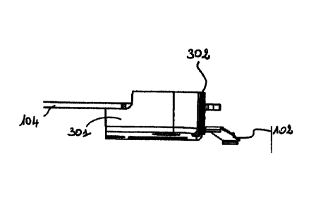
Figure 3, according to one particular embodiment of the invention, first of
all illustrates
the plastic part 301 of the coupling device as well as the electronic card (or
printed circuit board)
104 of the electronic payment terminal and the metal rail 102.
In this example, the plastic part 301 of the coupling device has a particular
shape intended
to provide for optimal performances of the antenna formed by the metal part
(not illustrated) of
the coupling device and the metal rail 102, while being adapted to possibly
other internal
constraints of the structure of the electronic payment terminal.
Thus, the plastic part 301 forming a support for the metal part of the
coupling device for
its part makes it possible to maintain with precision the required distance
between the metal part
Date Regue/Date Received 2022-11-18
7
of the coupling device and the metal rail in order to obtain the most
efficient coupling for the
antenna.
It must be noted that this distance, as well as the shape of the metal part of
the coupling
device, are predetermined for example according to the frequencies of the
radio technologies
given for the radio function of the electronic payment terminal and according
to certain
characteristics of the metal rail of the electronic payment terminal.
A more detailed description is now given of the interactions between the
different parts of
the coupling device and the elements of the electronic payment terminal with
reference to figures
4a to 4c.
These figures illustrate a particular embodiment of the invention,
respectively seen in a
front view, a profile view and top view. The shapes (and dimensions) of the
metal part 301 and
metal part 302 of the coupling device have been chosen purely to illustrate an
example of
positioning of the coupling device in the electronic payment terminal,
especially in relation to the
metal rail 102 and the printed circuit board 104. Those skilled in the art
will easily refer to their
own knowledge to determine the shapes best suited for both these parts of the
coupling device as
a function especially of the radiated performance desired for the radio
function and the
dimensions of the metal rail.
Thus, in figure 4a (which is a front view), the metal part 302 of the coupling
device is
represented in the form of a black-colored rectangle. This part 302 has a
thickness chosen to
enable optimal coupling with the metal rail, it being known that the plastic
part 301, through its
shape and its positioning on the printed circuit board 104 of the electronic
payment terminal,
enables an optimal position of the metal part relative to the metal rail 102.
For example, the metal part 302 corresponds to a fairly thin folded sheet
metal element.
Indeed, the thickness of the metal sheet for the metal part is not vital at
the desired frequencies of
use (because of the skin effect known to those skilled in the art). For
example, at 800 MHz (low
frequency), the skin effect gives a minimum critical thickness of about 2.5
pm. Hence a folded
sheet metal part with a thickness of 200 m can be suitable for example.
In figure 4b (side view), the metal part 302 is represented as hatched, as in
figure 4c (top
view) where the distance between the metal part 302 and the metal rail 102 can
be seen.
Date Regue/Date Received 2022-11-18
8
These figures therefore illustrate one of the main functions of the metal part
301 of the
coupling device which consists in forming a support for the metal part 302 so
as to ensure its
precise positioning relative to the metal rail 102. Indeed, as already
indicated here above, the
coupling between the different metal elements (metal part 302 and metal rail
102) of the antenna
greatly depends on the distance between these two elements.
Besides, different techniques of fixed attachment/assembly, such as for
example
"plastic/snap welding", can be implemented to fulfill the function in which
the metal part 302 is
supported by the plastic part 301. Any other technique enabling the assembly
of the plastic parts
and metal parts of the coupling device can be used.
Similarly, the plastic part 301 is assembled with the printed circuit board
104 of the
electronic payment terminal by being clipped on for example. Here again, any
other technique of
assembly enabling the plastic part 301 to be fixedly attached to the printed
circuit board 104 can
be implemented.
Finally, the metal part 302 is connected to the radio module 20 integrated
with the printed
circuit board 104 in a known way not described in detail in the present
application, to enable the
working of the antenna thus obtained by coupling this metal part and the metal
rail (present in the
electronic payment terminal to reinforce the passage of the magnetic card).
The integration of the coupling device formed by a metal part 302 connected to
the radio
module 20 of the electronic payment terminal and a plastic part 301 forming a
support for the
metal part and being itself assembled with the printed circuit board of the
electronic payment
terminal therefore makes it possible, according to the different embodiments
of the invention, to
optimize the radiated performance of the radio function of the electronic
payment terminal
without impairing the other functions of this payment terminal.
5.3 Other features and advantages
Another problem is also resolved by the present solution. This problem relates
to the
impact of electrostatic discharges on the electronic payment terminal, liable
especially to damage
the radio module.
Indeed, radio modules are generally not designed to withstand discharges of
more than 2
kV or even 6 kV, which is generally insufficient given the classic operation
of an electronic payment
Date Regue/Date Received 2022-11-18
9
terminal. To overcome this drawback, since the antennas are conductive, they
are generally made
inaccessible or are protected against any electrostatic attack (via the use of
a radome for
example), according to different techniques of the prior art.
Now, the solution according to the different embodiments of the invention
whereby the
metal rail is integrated into the implementation of the radio function of the
electronic payment
terminal and more particularly into the antenna makes it possible, via the
coupling between the
coupling device and the metal rail, to isolate the radio module of the
electronic payment terminal
and therefore protect it against electrostatic attacks despite the
accessibility of this metal rail and
its exposure to electrostatic discharges.
The approach according to the different embodiments of the invention therefore
improves
radiated performance without compromise between the function of reading the
magnetic stripe
of a card, the performance of the radio antenna and immunity against
electrostatic attacks.
Date Regue/Date Received 2022-11-18