Note: Descriptions are shown in the official language in which they were submitted.
CA 02938655 2016-08-03
WO 2015/147955
PCT/US2015/010257
SYSTEMS AND METHODS FOR PRIORITIZATION OF
WIRELESS CONTROL OF A WELDING POWER SUPPLY
BACKGROUND
[0001] The invention relates generally to welding systems and, more
particularly,
to the use of wireless remote control devices to control welding power supply
units.
[0002] Welding power supply units are welding systems configured to convert
input power to welding output power suitable for use in a welding operation.
In
certain embodiments, the welding power supply units even generate the power
that is
converted into the welding output power. Conventionally, welding power supply
units are controlled via a control panel disposed on an exterior surface of an
enclosure
of the welding power supply unit. However, often, welding operators perform
welding operations at locations that are at relatively large distances away
from the
welding power supply units. In such situations, the welding operators often
have to
walk all the way back to the welding power supply units to modify settings of
the
welding operations. As such, there is a need for the ability to control
welding power
supply units from relatively remote locations via wireless remote control
devices.
BRIEF DESCRIPTION
[0003] Embodiments described herein include wireless control of a welding
power supply via portable electronic devices, such as dedicated original
equipment
manufacturer (OEM) welding remote devices, cellular phones, laptops computers,
tablet computers, and so forth. In particular, operating parameters and
statuses of the
welding power supply may be modified by the portable electronic device, as
well as
be displayed on the portable electronic device. For example, in certain
embodiments,
the welding power supply may be an engine-driven welding power supply, and the
portable electronic device may be configured to start and/or stop an engine of
the
engine-driven welding power supply. A pairing procedure may be used to pair
the
welding power supply and the portable electronic device in a wireless
communication
network. Furthermore, in certain embodiments, a method of prioritization of
control
between a control panel of the welding power supply and the portable
electronic
1
device may be implemented to ensure that only one of the control panel of the
welding power
supply and the portable electronic device may be used to control the welding
power supply at any
given time.
[0003A] In a broad aspect, the present invention pertains to a welding
power supply
comprising power conversion circuitry configured to convert an input power
into an output power
for a welding operation. Control circuitry is configured to control operation
of the power
conversion circuitry to set prioritization of control of the welding power
supply between a control
panel of the welding power supply and a portable electronic device that is
wirelessly paired with
the welding power supply, via a wireless communication network, and to lock
out from controlling
at least one operational parameter of the welding power supply the one of the
control panel of the
welding supply or the portable electronic device that is not prioritized for
control of the welding
power supply. Transfer of the prioritization of control of the welding power
supply is enabled from
the control panel to the portable electronic device, and from the portable
electronic device to the
second panel. The control circuitry is configured to lock out from controlling
a plurality of all of
operational parameters of the welding power supply the one of the control
panel of the welding
power supply or the portable electronic device that is not prioritized for
control of the welding
power supply. The one of the control panel of the welding power supply or the
portable electronic
device that is not prioritized for control of the welding power supply is
adapted to change the
welding power supply from a powered on state to a powered off state.
[0003B] In a further aspect, the present invention embodies a method
comprising setting
prioritization of control of a welding power supply between a control panel of
the welding power
supply and a portable electronic device that is wirelessly paired with the
welding power supply, via
a wireless communication network. The method locks out from controlling at
least one operational
parameter of the welding power supply, the one of the control panel of the
welding power supply,
or the portable electronic device that is not prioritized for control of the
welding power supply, the
la
CA 2938655 2020-06-08
prioritization being set to either the control panel or the portable
electronic device. The transfer of
the prioritization of control of the welding power supply is enabled from the
control panel to the
portable electronic device, and from the portable electronic device to the
control panel. The method
also comprises locking out, from controlling a plurality or all of operational
parameters of the
welding power supply, the one of the control panel of the welding power supply
or the portable
electronic device that is not prioritized for control of the welding power
supply. The one of the
control panel of the welding power supply or the portable electronic device
that is not prioritized
for control of the welding power supply is adapted to changing the welding
power supply from a
powered on state to a powered off state.
b
CA 2938655 2020-06-08
=
DRAWINGS
[00041 These and other features, aspects, and advantages of the
present invention
will become better understood when the following detailed description is read
with
reference to the accompanying drawings in which like characters represent like
parts
throughout the drawings, wherein:
100051 FIG. 1 illustrates a welding-type system configured to
communicate
wirelessly with a wireless remote control device, in accordance with
embodiments of
the present disclosure;
100061 FIG. 2 is a block diagram of a wireless remote control device
configured to
communicate wirelessly with the welding-type system of FIG. 1, in accordance
with
embodiments of the present disclosure;
[00071 FIG. 3 illustrates an engine-driven welding power supply
configured to
communicate wirelessly with the wireless remote control device of FIG. 2, in
accordance with embodiments of the present disclosure;
[00081 FIG. 4 is a block diagram illustrating exemplary functional
components of
an embodiment of the engine-driven welding power supply of FIG. 3, in
accordance
with embodiments of the present disclosure;
[00091 FIG. 5 illustrates the wireless remote control device
configured to
wirelessly control an engine of the engine-driven welding power supply of FIG.
4, in
accordance with embodiments of the present disclosure;
100101 FIG. 6 illustrates the wireless remote control device
configured to
wirelessly control a compressor and a pump of the engine-driven welding power
supply of FIG. 4, in accordance with embodiments of the present disclosure;
2
CA 2938655 2020-06-08
CA 02938655 2016-08-03
WO 2015/147955
PCT/US2015/010257
[0011] FIG. 7 illustrates the wireless remote control device configured to
display
operating parameters and statuses of the engine-driven welding power supply of
FIG.
4, in accordance with embodiments of the present disclosure;
[0012] FIG. 8 illustrates the wireless remote control device configured to
display
diagnostic messages and diagnostic codes of the engine-driven welding power
supply
of FIG. 4, in accordance with embodiments of the present disclosure;
[0013] FIG. 9 illustrates the wireless remote control device configured to
wirelessly control welding parameters of the engine-driven welding power
supply of
FIG. 4, in accordance with embodiments of the present disclosure;
[0014] FIGS. 10A and 10B illustrate the wireless remote control device
configured to initiate pairing of the wireless remote control device with the
engine-
driven welding power supply of FIG. 4, in accordance with embodiments of the
present disclosure; and
[0015] FIG. 11 illustrates the wireless remote control device configured to
implement a find function for the wireless remote control device, in
accordance with
embodiments of the present disclosure.
DETAILED DESCRIPTION
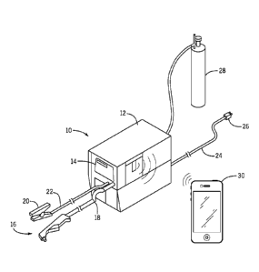
[0016] FIG. 1 illustrates a welding-type system 10 capable of performing
various
types of operations. The welding-type system 10 is merely representative of a
wide
variety of welding-type machines having various sizes, features, and ratings.
The
welding-type system 10, as contemplated herein, can be configured to not only
perform standard welding operations such as tungsten inert gas (TIG), metal
inert gas
(MIG), and/or stick welding, but can also be capable of performing various
cutting
operations that are closely associated with the various welding procedures,
such as
plasma cutting, for example. The welding-type system 10 includes a power
supply 12
to condition raw power and generate a power signal suitable for welding
applications.
The power supply 12 includes a control panel 14 through which an operator may
adjust operating parameters of the welding-type system 10. Connected to the
power
3
CA 02938655 2016-08-03
WO 2015/147955
PCT/US2015/010257
supply 12 is a torch 16 via a cable 18 that provides the torch 16 with power
and
compressed air or gas, where needed.
[0017] Also connected to the power supply 12 is a work clamp 20, which is
designed to connect to a workpiece (not shown) to be welded and provide a
return
path. Connecting the work clamp 20 to the power supply 12 is a cable 22
designed to
provide the return path for the welding current from the torch 16 through the
workpiece and the work clamp 20. Extending from a rear portion of the power
supply
12 is a power cable 24 having a plug 26 for connecting the power supply 12 to
either a
portable power supply (not shown) or a transmission line power receptacle (not
shown). Also connected to the power source is a gas source 28 configured to
supply a
gas flow to the welding torch 16.
[0018] As illustrated in FIG. 1, the power supply 12 may be configured to
communicate wirelessly with a wireless remote control device 30, which may be
a
portable electronic device specifically configured to function as a remote
control
device for the power supply 12 or may be any type of portable electronic
device, such
as smart phones, tablet computers, laptop computers, and so forth, that may
have
software or firmware (as well as security keys) installed thereon to control
the power
supply 12. In certain embodiments, the wireless remote control device 30 may
be
used at a welding application location relatively remote from the power supply
12, yet
still provide substantially the same display and input devices that the
control panel 14
of the power supply 12 provides. In other words, the wireless remote control
device
30 may be used as a remote control panel when it is not feasible or practical
to use the
control panel 14 on the power supply 12. However, it should be noted that the
embodiments presented herein enable for additional functionality of the
welding
power supply 12 to be controlled and/or monitored by the wireless remote
control
device 30, as described in greater detail herein.
[0019] A variety of wireless remote control devices 30 may employ the
techniques described herein. FIG. 2, for example, is a block diagram depicting
various components that may be present in a suitable wireless remote control
device
30 that may be used in the implementation of the present techniques. The
wireless
4
CA 02938655 2016-08-03
WO 2015/147955
PCT/US2015/010257
remote control device 30 may include a handheld electronic device, a tablet
computing device, a notebook computer, and so forth. In other embodiments, the
wireless remote control device 30 may include a welding-related device, such
as a
portable welding wire feeder, a welding helmet, a welding control pendant, a
foot
pedal, and so forth.
[0020] As illustrated in FIG. 2, the wireless remote control device 30 may
include, among other things, a display 32, input structures 34, input/output
(I/O) ports
36, one or more processor(s) 38, memory 40, nonvolatile storage 42, a network
interface 44, and a power source 46. The various functional blocks shown in
FIG. 2
may include hardware elements (including certain types of circuitry), software
elements (including computer code stored on a non-transitory computer-readable
medium), or a combination of both hardware and software elements. It should be
noted that FIG. 2 is merely one example of a particular implementation and is
intended to illustrate the types of components that may be present in the
wireless
remote control device 30. Indeed, the various depicted components (e.g., the
processor(s) 38) may be separate components, components of a single contained
module (e.g., a system-on-a-chip device), or may be incorporated wholly or
partially
within any of the other elements within the wireless remote control device 30.
The
components depicted in FIG. 2 may be embodied wholly or in part as machine-
readable instructions (e.g., software or firmware), hardware, or any
combination
thereof.
[0021] In the wireless remote control device 30 of FIG. 2, the display 32
may be
any suitable electronic display used to display image data (e.g., a liquid
crystal display
(LCD) or an organic light emitting diode (OLED) display). In some examples,
the
display 32 may represent one of the input structures 34, enabling users to
interact with
a user interface of the wireless remote control device 30. In some
embodiments, the
electronic display 32 may be a touch display that can detect multiple touches
at once.
Other input structures 34 of the wireless remote control device 30 may include
buttons, keyboards, mice, trackpads, rotating knobs, and the like. The I/O
ports 36
may enable the wireless remote control device 30 to interface with various
other
electronic devices.
CA 02938655 2016-08-03
WO 2015/147955
PCT/US2015/010257
[0022] The processor(s) 38 and/or other data processing circuitry may
execute
instructions and/or operate on data stored in the memory 40 and/or the
nonvolatile
storage 42. The memory 40 and the nonvolatile storage 42 may be any suitable
articles of manufacture that include tangible, non-transitory computer-
readable media
to store the instructions or data, such as random-access memory, read-only
memory,
rewritable flash memory, hard drives, and optical discs. By way of example, a
computer program product containing the instructions may include an operating
system or an application program. In certain embodiments, the instructions
stored in
the memory 40 and/or the nonvolatile storage 42 of the wireless remote control
device
30 may include software including instructions for enabling the wireless
communication with the welding power supply 12, including pairing with the
welding
power supply 12, enabling prioritization of control between the welding power
supply
12 and the wireless remote control device 30, enabling control of the welding
power
supply 12 via the wireless remote control device 30, and so forth.
Furthermore, in
certain embodiments, security keys that are used to check whether the wireless
remote
control device 30 is authorized to communicate with the welding power supply
12,
and vice versa, may be stored in the memory 40 and/or the nonvolatile storage
42 of
the wireless remote control device 30.
[0023] The network interface 44 may include, for example, one or more
interfaces
for a personal area network (PAN), such as a Bluetooth network, for a local
area
network (LAN), such as an 802.11x Wi-Fi network or a ZigBee network, and/or
for a
wide area network (WAN), such as a 4G or LTE cellular network. The power
source
46 of the wireless remote control device 30 may be any suitable source of
energy,
such as a rechargeable lithium polymer (Li-poly) battery and/or an alternating
current
(AC) power converter.
[0024] As mentioned above, the wireless remote control device 30 may take
the
form of a computer or other type of electronic device. Such computers may
generally
be portable (such as laptop, notebook, and tablet computers). In other
embodiments,
the wireless remote control device 30 may be, for example, a portable phone
(e.g., a
smart phone), a media player, a personal data organizer, or any combination of
such
devices. In particular, in certain embodiments, the wireless remote control
device 30
6
CA 02938655 2016-08-03
WO 2015/147955
PCT/US2015/010257
may be a cellular phone utilizing cellular, Bluetooth, or Wi-Fi to communicate
with
the power supply 12. In general, the wireless remote control device 30 is a
portable
electronic device, in other words, handheld or otherwise easily portable by a
single
human operator.
[0025] The wireless communication networking techniques described herein
enable seamless and secure exchange of welding parameters, as well as job
information and other user data, between the wireless remote control device 30
and
the power supply 12. Such wireless communication networking techniques enable
welding personnel or other industrial equipment personnel, with little or no
experience in areas of communication theory, radio frequency technology, or
information technology, to easily assemble and operate wireless communication
networks that include a plurality of various equipment and accessories. The
wireless
communication networking techniques described herein make it easy and
intuitive for
the aforementioned personnel to manually assemble a wireless network at the
job site,
and begin using such wireless networks to perform safe and secure control of
the
welding equipment and accessories, as well as exchange information with other
parties in the welding shop or at areas remote from the welding shop.
[0026] As discussed above, the power supply 12 illustrated in FIG. 1 is
merely
exemplary and not intended to be limiting. For example, in certain
embodiments, the
power supply 12 may be an engine-driven welding power supply, such as
illustrated
in FIG. 3. FIG. 4 is a block diagram illustrating exemplary functional
components of
an embodiment of the engine-driven welding power supply 12. In the illustrated
embodiment, instead of utilizing power from an external power source, the
engine-
driven power supply 12 includes an engine 48, a generator 50, and power
conversion
circuitry 52 for generating welding power via a welding output 54 for delivery
to the
welding torch 16 and, in certain embodiments, for generating auxiliary power
via an
auxiliary output 55 for delivery to auxiliary equipment 56, such as a second
welding
power supply, lighting systems, grinding machines, and so forth. The generator
50 is
coupled to the engine 48 via a shaft 57 that is configured to rotate, as
indicated by
arrow 58.
7
CA 02938655 2016-08-03
WO 2015/147955
PCT/US2015/010257
[0027] The power supply 12 includes a controller 60 configured to control
operation of the power supply 12. In particular, in certain embodiments, the
controller 60 of the power supply 12 includes one or more processor(s) 62
configured
to execute program instructions stored in a tangible non-transitory computer-
readable
medium, such as the memory 64. For example, in certain embodiments, the memory
64 may store software including instructions for controlling the components of
the
power supply 12, instructions for interacting with wireless communication
circuitry
66 to wirelessly communicate with the wireless remote control device 30,
security
keys that are used to check whether the wireless communication circuitry 66 is
authorized to communicate with the wireless remote control device 30, and vice
versa,
and so forth. The processor(s) 62 may include a general purpose processor,
system-
on-chip (SoC) device, application-specific integrated circuit (ASIC), or other
processor configuration. Similarly, the memory 64 may include, for example,
random-access memory (RAM), read-only memory (ROM), flash memory (e.g.,
NAND), and so forth.
[0028] During operation, a rotor of the generator 50 is driven into
rotation within
a stator of the generator 50 by the engine 48, thereby generating AC power.
That is,
the shaft 57 rotates, as shown by arrow 58, to transmit power from the engine
48 to
the generator 50. The shaft 57 also connects the engine 48 and the generator
50 for
proper alignment while resisting bending and axial loads. The engine 48 and
the
generator 50 cooperate to generate power that may be converted into the
welding
power via the welding output 54 and, in certain embodiments, the auxiliary
power via
the auxiliary output 55 by the power conversion circuitry 52.
[0029] The operation of the power supply 12 is regulated and controlled by
the
controller 60. For example, the controller 60 regulates and controls the
operation of
the engine 48 via a bi-directional exchange of information between the engine
48 and
the controller 60. The controller 60 may receive one or more inputs from the
operator
via the control panel 14 and may regulate engine performance according to the
operator inputs. For instance, a user may specify the type of welding process
(e.g.,
AC stick welding, AC TIG welding, DC stick welding, DC MIG welding, etc.),
voltage and/or current settings for the welding process, and so forth, and the
controller
8
CA 02938655 2016-08-03
WO 2015/147955
PCT/US2015/010257
60 may determine an appropriate engine speed, among many other operating
parameters, based on such inputs. The controller 60 may similarly control
operation
of the generator 50, the power conversion circuitry 52, and other components
of the
power supply 12.
[0030] As also
illustrated in FIG. 4, the power supply 12 includes wireless
communication circuitry 66 configured to facilitate wireless communication
with the
wireless remote control device 30. In certain
embodiments, the wireless
communication circuitry 66 may include RF communication circuitry, such as RF
transmitters and sensors. In other embodiments, a radio subsystem and an
associated
signaling protocol may be implemented to wirelessly send and receive commands
and
data between the power supply 12 and the wireless remote control device 30.
However, in other embodiments, any suitable means for communicating wirelessly
between the power supply 12 and the wireless remote control device 30 may be
utilized. In addition, in certain embodiments, the wireless communication
circuitry 66
may include one or more processor(s) (i.e., similar to the one or more
processor(s) 62
of the controller 60 of the power supply 12) configured to execute program
instructions stored in a tangible non-transitory computer-readable medium
(i.e.,
similar to the memory 64 of the controller 60 of the power supply 12) for
enabling the
wireless communication with the wireless remote control device 30, including
pairing
with the wireless remote control device 30, enabling prioritization of control
between
the welding power supply 12 and the wireless remote control device 30,
enabling
control of the welding power supply 12 via the wireless remote control device
30, and
so forth. Furthermore, in certain embodiments, security keys that are used to
check
whether the wireless communication circuitry 66 is authorized to communicate
with
the wireless remote control device 30, and vice versa, may be stored in the
computer-
readable medium of the wireless communication circuitry 66. It will be
appreciated
that while the controller 60 and the wireless communication circuitry 66 are
described
herein as being separate components, in certain embodiments, the controller 60
and
the wireless communication circuitry 66 may collectively function as
integrated
control circuitry of the welding power supply 12.
9
CA 02938655 2016-08-03
WO 2015/147955
PCT/US2015/010257
[0031] In certain embodiments, all of the components, including the
wireless
communication circuitry 66, of the welding power supply 12 illustrated in FIG.
4 may
be disposed in a common housing (i.e., enclosure) 67. In such embodiments, the
wireless communication circuitry 66 functions as the coordinator for the
wireless
communication network 122 between the welding power supply 12 and the wireless
remote control device 30 local to (e.g., resident within) the welding power
supply 12,
as opposed to having coordination functionality being located remote from
(e.g.,
external to) the welding power supply 12. However, in other embodiments, the
wireless communication circuitry 66 may be disposed external to the housing 67
of
the welding power supply 12. For example, in certain embodiments, the wireless
communication circuitry 66 may be disposed in a separate housing that is
configured
to directly connect to the welding power supply 12. In particular, the
separate
housing that encompasses the wireless communication circuitry 66 may include
one
or more external connectors disposed on the housing that are configured to
mate with
one or more ports on the welding power supply 12 (e.g., via the control panel
14, for
example), thereby enabling the wireless communication circuitry 66 to
communicate
with the controller 60 of the welding power supply 12, the control panel 14 of
the
welding power supply 12, and so forth. As such, in certain embodiments, the
wireless
remote control functionality enabled by the wireless communication circuitry
66 as
described herein may be retrofitted into pre-existing welding power supplies
12. It
will be appreciated that once such a retrofit communication module is
connected to a
pre-existing welding power supply 12, the wireless communication circuitry 66
of the
retrofit communication module may cooperate with the controller 60, control
panel
14, and all other components, of the welding power supply 12 as described
herein to
enable the wireless control functionality for a wireless remote control device
30.
[0032] As previously discussed, although illustrated in FIG. 4 as including
an
engine-driven welding power supply 12, the wireless remote control protocols
and
methods described herein may be used with any type of welding power supplies,
line-
powered, engine-driven, or otherwise. For example, in certain embodiments, as
opposed to being an engine-driven welding power supply 12 having an engine 48
that
drives a generator 50 to produce power that is converted into welding power
via a
CA 02938655 2016-08-03
WO 2015/147955
PCT/US2015/010257
welding output 54 and, in certain embodiments, auxiliary power via an
auxiliary
output 55 by the power conversion circuitry 52, the welding power supply 12
may
instead receive power from an external source, such as an electrical grid, and
the
power conversion circuitry 52 may convert this power to the welding power via
the
welding output 54, the auxiliary power via the auxiliary output 55, and so
forth.
[0033] In general, all of the components illustrated in FIG. 4 as being
included in
the welding power supply 12 may be disposed in a common housing or enclosure
67
of the welding power supply 12. For example, in certain embodiments, the
welding
power supply 12 may include a compressor 68 that is powered by the engine 48
and/or the generator 50, and is utilized to produce compressed air 70 for use
in the
welding application, without the need for an intermediate storage tank. For
example,
although not illustrated in FIG. 4, in certain embodiments, the compressor 68
may be
coupled to the engine 48 (e.g., directly via a shaft or indirectly via a
system of belts)
and driven by the engine 48. In other embodiments, the compressor 68 may be
directly or indirectly coupled to, and driven by, the generator 50. In
addition, in
certain embodiments, the welding power supply 12 may include a hydraulic pump
72
that is powered by the engine 48 and/or the generator 50, and is utilized to
pump
fluids 74 for use in the welding application. For example, although not
illustrated in
FIG. 4, in certain embodiments, the hydraulic pump 72 may be coupled to the
engine
48 (e.g., directly via a shaft or indirectly via a system of belts) and driven
by the
engine 48. In other embodiments, the hydraulic pump 72 may be directly or
indirectly
coupled to, and driven by, the generator 50.
[0034] Once the wireless remote control device 30 and the welding power
supply
12 are paired with each other, as described in greater detail herein, any
number of
operational parameters and statuses of the welding power supply 12 may be
controlled
by the wireless remote control device 30. For example, in certain embodiments,
the
engine 48 of the welding power supply 12 may be started using the wireless
remote
control device 30. In such an embodiment, a user of the wireless remote
control
device 30 may, for example, press a start button on the wireless remote
control device
30 or a virtual start button 76 on the display 32 of the wireless remote
control device
30, as illustrated in FIG. 5, thereby causing a control signal to be sent
wirelessly from
11
CA 02938655 2016-08-03
WO 2015/147955
PCT/US2015/010257
the wireless remote control device 30 to the controller 60 of the welding
power supply
12 via the wireless communication circuitry 66 of the welding power supply 12.
In
response to this control signal, based at least in part on the received
control signal (as
well as other operating parameters, in certain embodiments), the controller 60
may
cause the engine 48 of the welding power supply 12 to start, thereby
generating power
for the welding operation of the welding power supply 12.
[0035] Conversely, in certain embodiments, the engine 48 of the welding
power
supply 12 may also be stopped using the wireless remote control device 30. In
such
an embodiment, a user of the wireless remote control device 30 may, for
example,
press a stop button on the wireless remote control device 30 or a virtual stop
button 78
on the display 32 of the wireless remote control device 30, as illustrated in
FIG. 5,
thereby causing a control signal to be sent wirelessly from the wireless
remote control
device 30 to the controller 60 of the welding power supply 12 via the wireless
communication circuitry 66 of the welding power supply 12. In response to this
control signal, the controller 60 may cause the engine 48 of the welding power
supply
12 to stop, thereby ceasing generation of power for the welding operation of
the
welding power supply 12. In addition, the current operating status (i.e., ON
or OFF)
of the engine 48 may be communicated to the wireless remote control device 30
wirelessly from the controller 60 of the welding power supply 12 via the
wireless
communication circuitry 66, and indicated on an indicator on the wireless
remote
control device 30 or a virtual indicator 80 on the display 32 of the wireless
remote
control device 30, as illustrated in FIG. 5.
[0036] The following descriptions detail certain specifics relating to
remote
starting and stopping of the engine 48 of the welding power supply 12. The
wireless
remote control device 30 may start the engine 48 with the following exemplary
sequence. First, the wireless remote control device 30 may be paired with the
welding
power supply 12, as described in greater detail herein. The welding power
supply 12
may be in an OFF position with the engine 48 stopped. The operator may then
place
the engine 48 in a RUN position. The operator may then press the start button
76 on
the wireless remote control device 30, thereby placing the welding power
supply 12 in
wireless mode while the wireless remote control device 30 sends an engine
start
12
CA 02938655 2016-08-03
WO 2015/147955
PCT/US2015/010257
request message wirelessly to the controller 60 of the welding power supply
12. In
response to this engine start request message, the controller 60 of the
welding power
supply 12 executes an engine start sequence as governed by local closed loop
control.
In addition, the controller 60 may send engine RPM data to the wireless remote
control device 30 at time intervals to serve as an engine start status
indication to the
operator via the wireless remote control device 30, where the engine RPM is
displayed on the display 32 of the wireless remote control device 30 (e.g.,
when the
engine 48 of the welding power supply 12 reaches its operating RPM, a valid
start
sequence is indicated). Similarly, to perform an engine stop sequence for the
welding
power supply 12, the stop button 78 on the wireless remote control device 30
may be
pressed, and a message sent to the welding power supply 12, which then
performs an
engine stop sequence. The engine RPM may again be transmitted to the wireless
remote control device 30 to indicate engine status to the operator via the
wireless
remote control device 30.
[0037] In addition to enabling remote starting and/or stopping of the
engine 48 of
the welding power supply 12, in certain embodiments, the operating speed of
the
engine 48 may be displayed on the wireless remote control device 30 and
controlled
via control elements on the wireless remote control device 30. For example,
the
operating speed of the engine 48 may be communicated to the wireless remote
control
device 30 wirelessly from the controller 60 of the welding power supply 12 via
the
wireless communication circuitry 66, and indicated on an indicator of the
wireless
remote control device 30 or a virtual indicator 82 on the display 32 of the
wireless
remote control device 30, as illustrated in FIG. 5. Furthermore, in certain
embodiments, a user of the wireless remote control device 30 may, for example,
manipulate increase/decrease slider elements on the wireless remote control
device 30
or virtual increase/decrease slider elements 84, 86 on the display 32 of the
wireless
remote control device 30, as illustrated in FIG. 5, thereby causing a control
signal to
be sent wirelessly from the wireless remote control device 30 to the
controller 60 of
the welding power supply 12 via the wireless communication circuitry 66 of the
welding power supply 12, the control signal being used by the controller 60 to
increase or decrease the operating speed of the engine 48 of the welding power
supply
13
12 based at least in part on the received control signal (as well as other
operating
parameters, in certain embodiments).
[0038] In addition, in certain embodiments, instead of directly
manipulating the
operating speed of the engine 48 using the wireless remote control device 30,
the user
may instead change an operating mode of the engine 48, such as Auto (auto
idle) or
Run (high speed lock), among others. In other words, instead of the user
setting the
actual speed of the engine 48 at his discretion, an operating speed mode may
instead
be selected using the wireless remote control device 30. Examples of the types
of
engine control modes that may be controlled by the user using the wireless
remote
control device 30 are described in U.S. Patent Application Publication No.
2010/0193489, entitled "INTEGRATED ENGINE-DRIVEN GENERATOR
CONTROL SYSTEM, "filed Jan 30, 2009, which may be referred to for further
details.
[0039] In addition, in certain embodiments, a means for enabling an
auto-start
feature when using the wireless remote control device 30 may be implemented.
The
auto-start feature is used to initiate an engine start if, for example, when
in stick
welding mode, the operator touches the welding rod to the grounded surface.
When
such an event occurs, a unique command may be sent from the wireless remote
control device 30 to the welding power supply 12, and the engine 48 may be
started
based at least in part on the command. Other load detections may also initiate
the
auto-start feature. For example, an engine start may be initiated if a welding
arc is
detected (e.g., when a battery is used in the welding power supply 12), if a
trigger of a
MIG welding torch is pressed, if a foot pedal coupled to the welding power
supply 12
is depressed for TIG welding, if a TIG welding torch is touched to the
grounded
surface, if amperage and/or voltage of an auxiliary load is detected, if a
load on the
compressor 68 is detected (e.g., a compressor pressure or change in compressor
pressure is detected), if a load on the hydraulic pump 72 is detected (e.g., a
hydraulic
pump pressure or change in hydraulic pump pressure is detected), if a low
battery
condition (e.g., when a battery power level falls below a predetermined
threshold) for
the welding power supply 12 (or any components connected to the welding power
supply 12, for that matter) is detected, and so forth. Furthermore, in certain
14
CA 2938655 2017-11-24
CA 02938655 2016-08-03
WO 2015/147955
PCT/US2015/010257
embodiments, a means for enabling an auto-stop (i.e., auto-shutdown) feature
when
using the wireless remote control device 30 may be implemented. The auto-stop
feature is used to initiate an engine stop based, for example, on weld and
load times
(e.g., an amount of time without activity of the welding power supply 12, such
as
welding operations, auxiliary load operations, compressed air delivery
operations,
hydraulic fluid delivery operations), and so forth.
[0040] It will be appreciated that the events occurring in the welding
power
supply 12 or devices coupled to the welding power supply 12 for enabling the
auto-
start and auto-stop features may be detected in a number of ways. For example,
in
certain embodiments, the welding power supply 12 and/or the devices (e.g.,
stick
welding clamp hold a stick welding rod, MIG welding torch, TIG welding torch,
foot
pedal, auxiliary load, compressor 68, hydraulic pump 72, and so forth) coupled
to the
welding power supply 12 may include sensors specifically configured to detect
the
events that initiate the automatic starting and/or automatic stopping of the
engine 48.
[0041] Furthermore, in certain embodiments, an autospeed selector on the
wireless remote control device 30 or a virtual autospeed selector 88 on the
display 32
of the wireless remote control device 30, as illustrated in FIG. 5, may be
selected or
deselected by the user, and an autospeed setting may be sent to the controller
60 of the
welding power supply 12 consistent with the selection. In general, when the
autospeed setting is selected, the operating speed of the engine 48 of the
welding
power supply 12 will be automatically determined and established based on
current
welding operating parameters (e.g., voltage, current, and so forth) of a
welding
operation being performed by the welding torch 16, auxiliary load
requirements,
compressed air delivery requirements, hydraulic fluid delivery requirements,
battery
power levels, and so forth. Conversely, when the autospeed setting is
deselected, the
operating speed of the engine 48 of the welding power supply 12 will be set at
a
predetermined value (e.g., at a given speed selected by the user via the
increase/decrease slider elements, as described above).
[0042] In addition to wirelessly controlling operation of the engine 48 of
the
welding power supply 12, in certain embodiments, the wireless remote control
device
CA 02938655 2016-08-03
WO 2015/147955
PCT/US2015/010257
30 may be configured to wirelessly control other components of the welding
power
supply 12. For example, in certain embodiments, the compressor 68 of the
welding
power supply 12 may be started using the wireless remote control device 30. In
such
an embodiment, a user of the wireless remote control device 30 may, for
example,
press a start button on the wireless remote control device 30 or a virtual
start button
90 on the display 32 of the wireless remote control device 30, as illustrated
in FIG. 6,
thereby causing a control signal to be sent wirelessly from the wireless
remote control
device 30 to the controller 60 of the welding power supply 12 via the wireless
communication circuitry 66 of the welding power supply 12. Based at least in
part on
the received control signal (as well as other operating parameters, in certain
embodiments), the controller 60 may cause the compressor 68 of the welding
power
supply 12 to start.
[0043] Conversely, in certain embodiments, the compressor 68 of the welding
power supply 12 may also be stopped using the wireless remote control device
30. In
such an embodiment, a user of the wireless remote control device 30 may, for
example, press a stop button on the wireless remote control device 30 or a
virtual stop
button 92 on the display 32 of the wireless remote control device 30, as
illustrated in
FIG. 6, thereby causing a control signal to be sent wirelessly from the
wireless remote
control device 30 to the controller 60 of the welding power supply 12 via the
wireless
communication circuitry 66 of the welding power supply 12. Based at least in
part on
the received control signal (as well as other operating parameters, in certain
embodiments), the controller 60 may cause the compressor 68 of the welding
power
supply 12 to stop.
[0044] In addition, the current operating status (i.e., ON or OFF) of the
compressor 68 may be communicated to the wireless remote control device 30
wirelessly from the controller 60 of the welding power supply 12 via the
wireless
communication circuitry 66, and indicated on an indicator on the wireless
remote
control device 30 or a virtual indicator 94 on the display 32 of the wireless
remote
control device 30, as illustrated in FIG. 6. It will be appreciated that other
operating
parameters and statuses of the compressor 68 may be wirelessly controlled by
the
wireless remote control device 30 and displayed on the wireless remote control
device
16
CA 02938655 2016-08-03
WO 2015/147955
PCT/US2015/010257
30. It will further be appreciated that any type of welding power supply 12,
line-
powered, engine-driven, or otherwise, may include the compressor 68, and that
the
wireless remote control device 30 may control the compressor 68 as described
herein.
[0045] Furthermore, in certain embodiments, the hydraulic pump 72 of the
welding power supply 12 may be started using the wireless remote control
device 30.
In such an embodiment, a user of the wireless remote control device 30 may,
for
example, press a start button on the wireless remote control device 30 or a
virtual start
button 96 on the display 32 of the wireless remote control device 30, as
illustrated in
FIG. 6, thereby causing a control signal to be sent wirelessly from the
wireless remote
control device 30 to the controller 60 of the welding power supply 12 via the
wireless
communication circuitry 66 of the welding power supply 12. Based at least in
part on
the received control signal (as well as other operating parameters, in certain
embodiments), the controller 60 may cause the hydraulic pump 72 of the welding
power supply 12 to start.
[0046] Conversely, in certain embodiments, the hydraulic pump 72 of the
welding
power supply 12 may also be stopped using the wireless remote control device
30. In
such an embodiment, a user of the wireless remote control device 30 may, for
example, press a stop button on the wireless remote control device 30 or a
virtual stop
button 98 on the display 32 of the wireless remote control device 30, as
illustrated in
FIG. 6, thereby causing a control signal to be sent wirelessly from the
wireless remote
control device 30 to the controller 60 of the welding power supply 12 via the
wireless
communication circuitry 66 of the welding power supply 12. Based at least in
part on
the received control signal (as well as other operating parameters, in certain
embodiments), the controller 60 may cause the hydraulic pump 72 of the welding
power supply 12 to stop.
[0047] In addition, the current operating status (i.e., ON or OFF) of the
hydraulic
pump 72 may be communicated to the wireless remote control device 30
wirelessly
from the controller 60 of the welding power supply 12 via the wireless
communication circuitry 66, and indicated on an indicator on the wireless
remote
control device 30 or a virtual indicator 100 on the display 32 of the wireless
remote
17
CA 02938655 2016-08-03
WO 2015/147955
PCT/US2015/010257
control device 30, as illustrated in FIG. 6. It will be appreciated that other
operating
parameters and statuses of the hydraulic pump 72 may be wirelessly controlled
by the
wireless remote control device 30 and displayed on the wireless remote control
device
30.
[0048] Furthermore, in certain embodiments, the welding output 54 of the
welding power supply 12 may be turned on and off (e.g., a contactor, a solid
state
control, or some other mechanism, may be activated or deactivated) using the
wireless
remote control device 30. In addition, the current operating status (i.e., ON
or OFF)
of the welding output 54 may be communicated to the wireless remote control
device
30 wirelessly from the controller 60 of the welding power supply 12 via the
wireless
communication circuitry 66, and indicated on the wireless remote control
device 30.
It will be appreciated that any type of welding power supply 12, line-powered,
engine-driven, or otherwise, may communicate with the wireless remote control
device 30 in this manner.
[0049] Many other operating parameters and statuses of the welding power
supply
12 may be wirelessly communicated to the wireless remote control device 30
from the
controller 60 of the welding power supply 12 via the wireless communication
circuitry 66, and displayed on indicators of the wireless remote control
device 30 or
virtual indicators on the display 32 of the wireless remote control device 30.
For
example, as illustrated in FIG. 7, in certain embodiments, the current engine
fuel level
of the engine 48 of the welding power supply 12 may be displayed on a virtual
indicator 102 on the display 32 of the wireless remote control device 30. In
addition,
in certain embodiments, an estimated time until a next scheduled oil change
for the
engine 48 of the welding power supply 12 may be displayed on a virtual
indicator 104
on the display 32 of the wireless remote control device 30. This estimated
time may
be calculated by the controller 60 of the welding power supply 12 based on oil
measurements and/or usage statistics of the engine 48 that are collected by
the
controller 60. Furthermore, in certain embodiments, the total amount of time
(e.g.,
lifetime hours) the engine 48 has been in use may be displayed on a virtual
indicator
105 on the display 32 of the wireless remote control device 30. In addition,
in certain
embodiments, the total amount of time (e.g., lifetime hours) the welding power
supply
18
CA 02938655 2016-08-03
WO 2015/147955
PCT/US2015/010257
12 in general has been in use may also be displayed on the display 32 of the
wireless
remote control device 30. It will be appreciated that any type of welding
power
supply 12, line-powered, engine-driven, or otherwise, may communicate with the
wireless remote control device 30 in this manner.
[0050] In addition, as illustrated in FIG. 8, in certain embodiments,
engine
diagnostic messages and/or diagnostic codes for the engine 48 of the welding
power
supply 12 may be indicated on virtual indicators 106, 108 on the display 32 of
the
wireless remote control device 30. It will be appreciated that using the
wireless
remote control device 30 to wirelessly control the welding power supply 12 may
facilitate communication of engine diagnostic messages and/or diagnostic codes
that
may otherwise not be communicable to the user, for example, via the control
panel 14
of the welding power supply 12. For example, in certain embodiments, the
control
panel 14 of the welding power supply 12 may not include a display capable of
displaying detailed diagnostic messages, whereas the display 32 of the
wireless
remote control device 30 is capable of displaying myriad detailed diagnostic
messages.
[0051] Indeed, in certain embodiments, all available engine parametrics and
diagnostics are available via messages between the welding power supply 12 and
the
wireless remote control device 30. Examples of such engine parametrics and
diagnostics include, but are not limited to, low oil pressure, low or high oil
or coolant
temperatures, low battery voltage level, low fuel pressure, oxygen sensor
readings,
excessive total engine hours (e.g., excessive total engine hours since last
oil change or
service), malfunction codes, and so forth. In certain embodiments, the list of
such
messages is entirely programmable and can be tailored for the engine 48 of the
welding power supply 12. For example, in certain embodiments, for a welding
power
supply 12 that utilizes electronic fuel injection (EFT), the engine 48 may be
manufactured by Kohler and include a serial data bus with streaming data from
the
Kohler EF1 module. In certain embodiments, the wireless communication
circuitry 66
facilitates the wireless remote control device 30 having access to (e.g., to
assume a
master of) the serial data bus of the engine 48. Any or all of the data may be
presented to the control electronics (e.g., the controller 60 of the welding
power
19
CA 02938655 2016-08-03
WO 2015/147955
PCT/US2015/010257
supply 12), stored in local memory (e.g., the memory 64 of the controller 60)
for
retrieval at a later time, uploaded to an intemet-based data server (e.g.,
using an in-
system Wi-Fi, Ethernet, cellular, Bluetooth, ZigBee-to-Internet bridge, etc.)
or
transmitted to the wireless remote control device 30. Examples of engine
parametric
and diagnostic data possible include, but are not limited to, engine RPM,
engine fuel
status or level, total engine hours, expected hours to next service (e.g.,
such as oil
change), engine diagnostic codes (which may vary with the engine 48 used),
machine
diagnostics codes (such as semiconductor module temperatures), network error
codes,
and so forth.
[0052] Although illustrated in FIG. 8 as relating to engine diagnostic
messages
and/or diagnostic codes, diagnostic messages and/or diagnostic codes for the
welding
power supply 12 in general (e.g., temperature too high, current too high,
voltage too
low or too high, thermistor failure, PC board failure, power supply failure,
and so
forth), for all of the major components of the welding power supply 12 (e.g.,
the
generator 50, the compressor 68, the hydraulic pump 72, the power conversion
circuitry 52, the welding power output 54, the auxiliary power output 55, the
controller 60, the wireless communication circuitry 66, and so forth) as well
as the
devices connected to the welding power supply 12 (e.g., the welding torch 16,
the
wired accessory 132, and so forth) may be indicated on the display 32 of the
wireless
remote control device 30. It will be appreciated that any type of welding
power
supply 12, line-powered, engine-driven, or otherwise, may communicate with the
wireless remote control device 30 in this manner.
[0053] The information and virtual control elements displayed on the
display 32
of the wireless remote control device 30 illustrated in FIGS. 5 through 8 are
merely
exemplary of the types of information and control elements that may be
available on
the wireless remote control device 30. In particular, it is noted that all of
the
information and virtual control elements displayed on the display 32 of the
wireless
remote control device 30 illustrated in FIGS. 5 through 8 are typical of an
engine-
driven welding power supply 12. However, as previously discussed, the wireless
remote control device 30 may be used to control any type of welding power
supply
12, line-powered, engine-driven, or otherwise.
CA 02938655 2016-08-03
WO 2015/147955
PCT/US2015/010257
[0054] In certain embodiments, the wireless remote control device 30 may be
used to wirelessly control operating parameters relating to the welding output
54 of
the welding power supply 12, which may affect the delivery of the welding
power to
the welding torch 16. For example, as illustrated in FIG. 9, in certain
embodiments,
the type of welding process (e.g., stick, MIG, TIG, etc.) being performed by
the
welding power supply 12 may be controlled by the wireless remote control
device 30.
In such an embodiment, a user of the wireless remote control device 30 may
select the
type of welding process being performed by the welding power supply 12 via a
selector on the wireless remote control device 30 or a virtual selector 110 on
the
display 32 of the wireless remote control device 30, as illustrated in FIG. 9.
Based on
the selection, a control signal may be sent wirelessly from the wireless
remote control
device 30 to the controller 60 of the welding power supply 12 via the wireless
communication circuitry 66 of the welding power supply 12. In response to this
control signal, the controller 60 may change the type of welding process
consistent
with the selection made by the user via the wireless remote control device 30.
It will
be appreciated that any type of welding power supply 12, line-powered, engine-
driven, or otherwise, may communicate with the wireless remote control device
30 in
this manner.
[0055] In addition, the polarity (e.g., DCEN, DCEP, and so forth) of the
welding
process being performed by the welding power supply 12 may be controlled by
the
wireless remote control device 30. In such an embodiment, a user of the
wireless
remote control device 30 may select the polarity of the welding process being
performed by the welding power supply 12 via a selector on the wireless remote
control device 30 or a virtual selector 112 on the display 32 of the wireless
remote
control device 30, as illustrated in FIG. 9. Based on the selection, a control
signal
may be sent wirelessly from the wireless remote control device 30 to the
controller 60
of the welding power supply 12 via the wireless communication circuitry 66 of
the
welding power supply 12. In response to this control signal, the controller 60
may
change the polarity of the welding process consistent with the selection made
by the
user via the wireless remote control device 30. It will be appreciated that
any type of
21
CA 02938655 2016-08-03
WO 2015/147955
PCT/US2015/010257
welding power supply 12, line-powered, engine-driven, or otherwise, may
communicate with the wireless remote control device 30 in this manner.
[0056] In addition, the current and/or voltage of the welding process being
performed by the welding power supply 12 may be displayed on the wireless
remote
control device 30 and controlled via control elements on the wireless remote
control
device 30. For example, the welding current being delivered to the welding
torch 16
via the welding output 54 of the welding power supply 12 may be communicated
to
the wireless remote control device 30 wirelessly from the controller 60 of the
welding
power supply 12 via the wireless communication circuitry 66, and indicated on
an
indicator of the wireless remote control device 30 or a virtual indicator 114
on the
display 32 of the wireless remote control device 30, as illustrated in FIG. 9.
[0057] Furthermore, in certain embodiments, a user of the wireless remote
control
device 30 may, for example, manipulate increase/decrease slider elements (or
buttons,
knobs, and so forth) on the wireless remote control device 30 or virtual
increase/decrease slider elements 116 (or virtual buttons, virtual knobs, and
so forth)
on the display 32 of the wireless remote control device 30, as illustrated in
FIG. 9,
thereby causing a control signal to be sent wirelessly from the wireless
remote control
device 30 to the controller 60 of the welding power supply 12 via the wireless
communication circuitry 66 of the welding power supply 12, the control signal
being
used by the controller 60 to increase or decrease the welding current being
delivered
to the welding torch 16 via the welding output 54 of the welding power supply
12. It
will be appreciated that any type of welding power supply 12, line-powered,
engine-
driven, or otherwise, may communicate with the wireless remote control device
30 in
this manner.
[0058] Similarly, the welding voltage being delivered to the welding torch
16 via
the welding output 54 of the welding power supply 12 may be communicated to
the
wireless remote control device 30 wirelessly from the controller 60 of the
welding
power supply 12 via the wireless communication circuitry 66, and indicated on
an
indicator of the wireless remote control device 30 or a virtual indicator 118
on the
display 32 of the wireless remote control device 30, as illustrated in FIG. 9.
22
CA 02938655 2016-08-03
WO 2015/147955
PCT/US2015/010257
[0059] Furthermore, in certain embodiments, a user of the wireless remote
control
device 30 may, for example, manipulate increase/decrease slider elements on
the
wireless remote control device 30 or virtual increase/decrease slider elements
120 on
the display 32 of the wireless remote control device 30, as illustrated in
FIG. 9,
thereby causing a control signal to be sent wirelessly from the wireless
remote control
device 30 to the controller 60 of the welding power supply 12 via the wireless
communication circuitry 66 of the welding power supply 12, the control signal
being
used by the controller 60 to increase or decrease the welding voltage being
delivered
to the welding torch 16 via the welding output 54 of the welding power supply
12. It
will be appreciated that any type of welding power supply 12, line-powered,
engine-
driven, or otherwise, may communicate with the wireless remote control device
30 in
this manner.
[0060] Other operating parameters of the welding power supply 12 may be
wirelessly controlled by the wireless remote control device 30 and other
operating
parameters and statuses of the welding power supply 12 may be indicated on the
wireless remote control device 30. In other words, the operating parameters
and
statuses described with respect to FIGS. 5 through 9 are merely exemplary, and
not
intended to be limiting. For example, in certain embodiments, in addition to
displaying and/or controlling welding voltage and welding current via the
wireless
remote control device 30, welding voltage presets and welding current presets
may be
displayed and/or controlled via the wireless remote control device 30. In
certain
embodiments, the presets may be displayed and/or controlled as actual welding
voltage preset values or actual welding current preset values, while in other
embodiments, the presets may be displayed and/or controlled as percentages of
welding voltage or welding current.
[0061] It should be noted that the embodiments described herein enable a
level of
control of such voltage and current preset values that was previously
unattainable. In
particular, conventional techniques of controlling preset values such as
voltage and
current generally involve multiple conversions between digital and analog
values to
implement control of a welding power supply and to convey information to a
user
relating to such values. More specifically, in conventional techniques, a user
might
23
CA 02938655 2016-08-03
WO 2015/147955
PCT/US2015/010257
set a preset value for voltage or current using a control knob on a control
panel of a
welding power supply. The control knob used to adjust the preset value is
typically
attached to a potentiometer that adjusts an analog input that is used to
control the
welding power supply. Therefore, the preset value that is set by the user via
the
control knob is actually merely a reference value that corresponds to a change
in an
analog position of the potentiometer, rather than an actual preset value for
voltage or
control. Conversely, any value changes for voltage and current occurring in
the
welding power supply are communicated back through the control knob and other
control elements of the welding power supply via a conversion back from analog
positions and, as such, act only as approximations relative to reference
values
corresponding to these analog positions. As such, these conventional
techniques
transmit data through multiple digital-to-analog, and vice versa, conversions
that may
cause significant errors due to drift, offset, scaling, and so forth.
[0062] In contrast to these conventional techniques of control, the
embodiments
described herein enable purely digital information to be communicated between
(i.e.,
both to and from) the wireless remote control device 30 and the welding power
supply
12 and, indeed, all the way down to the weld control. As such, all changes in
control
values, including voltage and current preset values, are input and
communicated as
the exact digital values that are desired. Similarly, any changes to
operational values
of the welding power supply 12 are communicated to both the control panel 14
of the
welding power supply 12 and the display 32 of the wireless remote control
device 30
as more accurate digital values. Indeed, since these values are communicated
digitally, they will exactly match each other.
[0063] In addition, in certain embodiments, the arc that is created by the
welding
torch 16 may be controlled via the wireless remote control device 30. This arc
control, which may be referred to as Dig, enables a user of the welding power
supply
12 to adjust a variable amperage during low voltage (e.g., short arc length)
conditions
while welding, thereby helping to avoid -sticking" of the electrode when a
short arc
length is used. Such arc control may include arc force control, pulse timing,
induction
control, and other arc control settings that facilitate control of the arc. As
such, in
certain embodiments, an adjustment knob or slider on the wireless remote
control
24
CA 02938655 2016-08-03
WO 2015/147955
PCT/US2015/010257
device 30 (or a virtual adjustment knob or slider on the display 32 of the
wireless
remote control device 30) may be adjusted by the user (e.g., to select more or
less arc
control), thereby generating a control signal that is transmitted wirelessly
to the
controller 60 of the welding power supply 12, which adjusts an arc control
setting that
is used to effectuate the arc control that is selected by the user via the
wireless remote
control device 30 by, for example, adjusting a waveform of the welding power
delivered to the welding torch 16 via the welding output 54. It will be
appreciated
that any type of welding power supply 12, line-powered, engine-driven, or
otherwise,
may benefit from the control and display capabilities relating to general
welding
process parameters and statuses as described herein.
[0064] Returning now to FIG. 4, it will be appreciated that the network
interface
44 of the wireless remote control device 30 and the wireless communication
circuitry
66 of the welding power supply 12 are configured to communicate wirelessly
with
each other using any suitable wireless communication techniques. For example,
in
certain embodiments, the wireless remote control device 30 and the welding
power
supply 12 may implement an IEEE 802.15.4 radio subsystem with a ZigBee Pro
network stack that is modified to conceal a private network key such that only
wireless remote control devices 30 and welding power supplies 12 having the
particular type of radio systems may participate in a ZigBee network 122
established
between wireless remote control devices 30 and welding power supplies 12.
[0065] Before the wireless remote control device 30 may begin controlling
the
welding power supply 12, the wireless communication network 122 between the
wireless remote control device 30 and the welding power supply 12 must first
be
established. In certain embodiments, to establish the wireless communication
network 122 between the wireless remote control device 30 and the welding
power
supply 12, the wireless remote control device 30 and the welding power supply
12
may first be paired to each other. This pairing may be initialized by first
pressing a
button 124 (i.e., a first synchronization mechanism) on the wireless remote
control
device 30, as illustrated in FIG. 10A, or a virtual button (i.e., a first
synchronization
mechanism) on the display 32 of the wireless remote control device 30. Once
the
pairing procedure has been initiated, a message 126 may be displayed on the
display
CA 02938655 2016-08-03
WO 2015/147955
PCT/US2015/010257
32 of the wireless remote control device 30 that informs the user that a
similar button
(i.e., a second synchronization mechanism) on the welding power supply 12
needs to
be pressed to complete the pairing process of the wireless remote control
device 30
and the welding power supply 12 into the wireless communication network 122.
Once the button (i.e., the second synchronization mechanism) on the welding
power
supply 12 has been pressed, the network 122 may be established by the wireless
communication circuitry 66 of the welding power supply 12, which may function
as
the network coordinator in certain embodiments, as described in greater detail
herein.
In addition, a message 128 may be displayed on the display 32 of the wireless
remote
control device 30 that informs the user that the wireless communication
network 122
has been established, as illustrated in FIG. 10B.
[0066] In certain embodiments, the pairing of the wireless remote control
device
30 and the welding power supply 12 may only be initiated when the
synchronization
mechanisms (e.g., the buttons or virtual buttons) on the wireless remote
control device
30 and the welding power supply 12 are simultaneously activated (e.g.,
pressed).
However, it will be appreciated that in other embodiments, the pairing of the
wireless
remote control device 30 and the welding power supply 12 may be initiated when
the
synchronization mechanism on the welding power supply 12 is activated within a
given time period (e.g., within 15 seconds, within 10 seconds, within 5
seconds, and
so forth) after the initial pairing request from the wireless remote control
device 30.
[0067] Although initiation of the pairing process has been described as
being
performed from the wireless remote control device 30, it will be appreciated
that in
certain embodiments, initiation of the pairing process may be performed from
the
control panel 14 of the welding power supply 12, with the messages being
displayed
on a display on the control panel 14, the first button press being on the
control panel
14 of the welding power supply 12, and the second button press being on the
wireless
remote control device 30. Again, in certain embodiments, the pairing of the
wireless
remote control device 30 with the welding power supply 12 may only be
initiated
when the synchronization mechanisms (e.g., the buttons or virtual buttons) on
the
wireless remote control device 30 and the welding power supply 12 are
simultaneously activated (e.g., pressed). However, it will be appreciated that
in other
26
CA 02938655 2016-08-03
WO 2015/147955
PCT/US2015/010257
embodiments, the pairing of the wireless remote control device 30 and the
welding
power supply 12 may be accomplished when the synchronization mechanism on the
wireless remote control device 30 is activated within a given time period
(e.g., within
15 seconds, within 10 seconds, within 5 seconds, and so forth) after the
initial pairing
request from the welding power supply 12.
[0068] In addition, in other embodiments, other procedures for initiating
pairing
between the wireless remote control device 30 and the welding power supply 12
may
be used. For example, in certain embodiments, the pairing may be initiated by
first
pressing the button 124 on the wireless remote control device 30, as
illustrated in FIG.
10A, or a virtual button on the display 32 of the wireless remote control
device 30.
Once the pairing procedure has been initiated, confirmation of activation of
the button
124 or the virtual button on the display 32 of the wireless remote control
device 30
may be confirmed via the control panel 14 of the welding power supply 12, for
example, via a display on the control panel 14 or by activation of a button on
the
control panel 14. Conversely, in other embodiments, the pairing may be
initiated by
first pressing a button on the control panel 14 of the welding power supply
12. Once
the pairing procedure has been initiated, confirmation of activation of the
button on
the welding power supply 12 may be confirmed via the display of the wireless
remote
control device 30.
[0069] In other embodiments, the pairing process may be initiated by a user
entering certain identifying information (e.g., a serial number, a name, a
description, a
passcode, and so forth, or any combination thereof) relating to the welding
power
supply 12 via the display 32 of the wireless remote control device 30.
Alternatively,
the pairing process may be initiated by a user entering certain identifying
information
(e.g., a serial number, a name, a description, a passcode, and so forth, or
any
combination thereof) relating to the wireless remote control device 30 via the
control
panel 14 of the welding power supply 12. In such embodiments, assuming that
both
the wireless remote control device 30 and the welding power supply 12 include
the
appropriate security (e.g., encryption) keys, and that the information entered
by the
user is correct, the pairing between the wireless remote control device 30 and
the
welding power supply 12 is allowed.
27
CA 02938655 2016-08-03
WO 2015/147955
PCT/US2015/010257
[0070] In yet other embodiments, to facilitate initiation of the pairing
process, one
or more of the wireless remote control device 30 and the welding power supply
12
may be configured to provide a pairing cue to an operator, and information
relating to
the cue may be entered in the other of the wireless remote control device 30
and the
welding power supply 12. In certain embodiments, the pairing cue may be a
visual
indication (e.g., a flashing display, special characters on an alphanumeric
display,
flashing light emitting diodes, characters, or lamps that illuminate, and so
forth) or an
aural indication (e.g., a buzzer, a loudspeaker with a tone alert or a
recorded voice,
and so forth). Such embodiments facilitate pairing of welding power supplies
12 that
arc rack-mounted or otherwise not easily accessible by the operator.
[0071] In certain embodiments, once the pairing process has been initiated
by
either the wireless remote control device 30 or the welding power supply 12, a
power
level of the wireless communication circuitry 66 (e.g., a power level of a
radio
transmitter) of the welding power supply 12 may be reduced as a means to avoid
inadvertent pairing to unintended devices. In general, once the pairing
process has
been completed and the wireless communication network 122 has been established
between the welding power supply 12 and the wireless remote control device 30,
the
power level of the wireless communication circuitry 66 may be increased back
to a
normal level, for example, back to the power level before the pairing process
was
initiated.
[0072] Although many embodiments described herein relate to pairing of a
wireless remote control device 30 with a welding power supply 12 that is
initiated via
manual activation of certain features (e.g., buttons, and so forth) on both of
the
devices, in other embodiments, the pairing between a wireless remote control
device
30 and a welding power supply 12 may be initiated using other methods. For
example, a given wireless remote control device 30 may be pre-programmed to be
paired with a particular welding power supply 12, or vice versa, when
manufactured
in a factory. Furthermore, in other embodiments, instead of requiring
activation of
features on both the wireless remote control device 30 and the welding power
supply
12, pairing between the devices may be initiated via a single manual
synchronization
method. In other words, activation of only a feature on a wireless remote
control
28
CA 02938655 2016-08-03
WO 2015/147955
PCT/US2015/010257
device 30 may be sufficient to initiate synchronization (i.e., pairing) with a
welding
power supply 12. In such an embodiment, for example, once a user presses a
synchronization button on the wireless remote control device 30, a menu option
may
be displayed via the display 32 of the wireless remote control device 30,
whereby the
user can select a welding power supply 12 (from a list of welding power
supplies 12
having the requisite security keys, for example) with which to pair the
wireless remote
control device 30. It will be appreciated that a similar single manual
synchronization
pairing method may also be implemented from the control panel 14 of the
welding
power supply 12 as well, whereby the user selects a specific wireless remote
control
device 30 (from a list of wireless remote control devices 30 having the
requisite
security keys, for example) with which to pair the welding power supply 12.
[0073] In general, only one wireless remote control device 30 may be paired
with
one welding power supply 12 at any given time (i.e., the wireless remote
control
device 30 and the welding power supply 12 may only be paired together in a 1:1
pairing relationship). In other words, only one wireless remote control device
30 may
be capable of remotely controlling a given welding power supply 12 at any
given
time, and a given welding power supply 12 may only be capable of being
remotely
controlled by one wireless remote control device 30 at any given time.
[0074] However, in certain embodiments, more than one wireless remote
control
device 30 may be paired with a given welding power supply 12 at any given
time, and
these wireless remote control devices 30 may be used to control the welding
power
supply 12 in tandem. As a non-limiting example, in one embodiment, a wireless
foot
pedal may be used to control amperage of the welding output 54 of the welding
power
supply 12 and a wireless pendant may be used to control the type of welding
process,
starting and/or stopping of the welding power supply 12, and so forth. In such
embodiments, a certain type of wireless remote control device 30 may control a
certain subset of control features for the welding power supply 12, whereas
other
types of wireless remote control devices 30 may control other subsets of
control
features for the welding power supply 12, and the combined subsets of control
features may be complementary with each other. In the case where multiple
paired
wireless remote control devices 30 are both capable of controlling a given
feature
29
CA 02938655 2016-08-03
WO 2015/147955
PCT/US2015/010257
(e.g., parameter or status) for the welding power supply 12, certain
priorities between
the multiple paired wireless remote control devices 30 may be stored in the
memory
64 of the controller 60, and prioritization of control between the multiple
paired
wireless remote control devices 30 may be implemented accordingly.
[0075] At any given time after the welding power supply 12 and the wireless
remote control device 30 have been paired together, a de-pairing procedure may
be
performed to terminate the pairing between the welding power supply 12 and the
wireless remote control device 30. For example, a user may initiate
termination of the
pairing between a given welding power supply 12 and a paired wireless remote
control device 30 by interacting with either the control panel 14 of the
welding power
supply 12 or the wireless remote control device 30 (e.g., via the display 32
of the
wireless remote control device 30). For instance, an option to de-pair the
welding
power supply 12 from the wireless remote control device 30 may be selected by
the
user as an option in a menu presented via the display 32 of the wireless
remote control
device 30 (or, similarly, via the control panel 14 of the welding power supply
12).
Once de-pairing is initiated, the controller 60 of the welding power supply 12
may
cause the wireless communication circuitry 66 of the welding power supply 12
to
terminate the wireless communication network 122 between the welding power
supply 12 and the wireless remote control device 30, and signals may be sent
to both
the control panel 14 of the welding power supply 12 and the wireless remote
control
device 30 to display to users of the welding power supply 12 and the wireless
remote
control device 30 that the pairing has been terminated and the wireless
communication network 122 between the welding power supply 12 and the wireless
remote control device 30 no longer exists.
[0076] It will be appreciated that other events may initiate termination of
pairing
between a given welding power supply 12 and a paired wireless remote control
device
30. For example, in the event that the paired wireless remote control device
30 has
been outside of the range of the wireless communication network 122 for a
certain
period of time, the controller 60 of the welding power supply 12 may
automatically
initiate the de-pairing procedure described above. In such an event, the user
of the
welding power supply 12 may be provided with a prompt via the control panel 14
of
=
the welding power supply 12 to confirm that the user does, in fact, wish for
the
pairing between the welding power supply 12 and the wireless remote control
device
30 to be terminated. In certain situations, the user may instead wish to leave
the
wireless communication network 122 in place, and to simply bring the wireless
remote control device 30 back into the range of the wireless communication
network
122.
100771 In certain embodiments, de-pairing of the wireless remote control
device
30 and the welding power supply 12 may not be initiated unless the operator
performs
an intentional action like re-pairing the wireless remote control device 30
with another
welding power supply 12, re-pairing another wireless remote control device 30
to the
welding power supply 12, and so forth. Furthermore, the wireless communication
network 122 between the paired welding power supply 12 and wireless remote
control
device 30 is maintained even if the operator turns off the welding power
supply 12 or
the engine 48 of the welding power supply 12. It will be appreciated that any
type of
welding power supply 12, line-powered, engine-driven, or otherwise, may
utilize the
pairing and de-pairing techniques described herein in conjunction with the
wireless
remote control device 30.
[0078j In certain embodiments, once the welding power supply 12 and the
wireless remote control device 30 are paired together, the controller 60 of
the welding
power supply 12 functions as the ZigBee coordinator for the ZigBee network 122
created between the welding power supply 12 and the wireless remote control
device
30. In other words, the controller 60 of the welding power supply 12 may be
responsible for establishing the ZigBee network 122, maintaining wireless
communications via the ZigBee network 122, etc. The ZigBee coordinator
functionality of the controller 60 is similar to the functionality of the
master node
devices described in U.S. Patent Application Serial No. 13/795,639, entitled
"WIRELESS COMMUNICATION NETWORK FOR CONTROL OF INDUSTRIAL
EQUIPMENT IN HARSH ENVIRONMENTS," filed March 12, 2013, which may
be referred to for further details. It should be noted that the ZigBee
coordinator function-
ality need not necessarily reside in the welding power supply 12. Rather, in
other
embodiments, the ZigBee coordinator functionality may reside in a
31
CA 2938655 2017-11-24
CA 02938655 2016-08-03
WO 2015/147955
PCT/US2015/010257
separate master node device that facilitates communication between the welding
power supply 12 and the wireless remote control device 30. In yet other
embodiments, the ZigBee coordinator functionality may reside in the wireless
remote
control device 30. More specifically, the processor 38 of the wireless remote
control
device 30 may execute instructions stored on its memory 40 that carry out the
ZigBee
coordinator functionality of network association and security, improved
robustness,
power management and optimization, sensor data transmission, and so forth.
[0079] Furthermore,
while the wireless communication network 122 established
between the welding power supply 12 and the wireless remote control device 30
may
be a ZigBee network 122 (e.g., as message payloads in the 802.15.4 and ZigBee
descriptions) in certain embodiments, other types of wireless communication
networks may be established between the welding power supply 12 and the
wireless
remote control device 30, and the network coordinator functionality may be
consistent
with these other types of wireless communication networks. Any type of radio
standard capable of sending packetized data between the welding power supply
12
and the wireless remote control device 30 may be used to implement the
wireless
communication techniques described herein. In general,
in the wireless
communication network 122, there exists a so-called "master node", which
effects
management (i.e., coordination) of the wireless communication network 122.
Other
nodes may exist in the wireless communication network 122 for the purpose of
exchanging signals (e.g., commands, responses, data, and so forth), and these
other
nodes may assume local network addressing in conjunction with the master node.
In
some instances, the temporal relationship for data transfers on the wireless
communication network 122 (e.g., which node may send data, and when, and for
how
long, and so forth) is at least partially set by policy by the master node.
These
policies may vary based on the type of wireless communication network 122. For
example, for Wi-Fi networks (IEEE 802.11), the master node is an access point
(or
wireless access point); for Bluetooth networks (IEEE 802.15.1), there is a
master node
and a slave node; and for ZigBee networks (IEEE 802.15.4), there is a
coordinator
that sets the network for a collection of end nodes and routers.
32
CA 02938655 2016-08-03
WO 2015/147955
PCT/US2015/010257
[0080] The existing ZigBee and ZigBee Pro network definitions, as embodied
in
their respective network "stacks" and described within documents published by
the
ZigBee Alliance (www.zigbee.org) provide for open promiscuous network joining
of
all devices. However, the control of high-powered electrical equipment such as
the
welding power supply 12 described herein requires a higher level of security
and
reliability, both for security of data and for safety use concerns.
Accordingly, the
embodiments described herein implement more exclusive control over the welding
power supply 12 and the types of wireless remote control devices 30 that are
allowed
to join the wireless communication network 122 and to control the welding
power
supply 12. In particular, in certain embodiments, a modified version of the
released
ZigBee Pro software stack may be implemented, with modifications being made to
the security provisions, the pairing procedures, and so forth.
[0081] More specifically, the generic public ZigBee Pro stack generally
allows
any ZigBee device to join a network or to use network facilities (i.e.,
routers) to form
a larger mesh network. In contrast, the embodiments described herein restrict
all
network access to only those devices that are imprinted with security (e.g.,
encryption) keys. More specifically, in certain embodiments, all wireless
communication between the wireless remote control device 30 and the welding
power
supply 12 (including the pairing procedure) requires that both the wireless
remote
control device 30 and the welding power supply 12 include security keys stored
in
memory of the respective devices. During each communication between the
wireless
remote control device 30 and the welding power supply 12, the devices check
that the
requisite security keys are present and that the wireless communication may be
permitted.
[0082] In contrast to conventional techniques, in the embodiments described
herein, the security keys are not transmitted between the wireless remote
control
device 30 and the welding power supply 12. In other words, the security keys
are not
shared across the wireless communication network 122 between the wireless
remote
control device 30 and the welding power supply 12. Rather, again, the security
keys
are either installed in the devices during manufacture (e.g., in the case of
the welding
power supply 12, where the wireless remote control device 30 is an OEM
pendant,
33
CA 02938655 2016-08-03
WO 2015/147955
PCT/US2015/010257
and so forth) or are pre-loaded into the device prior to the wireless
communication
with the other device.
[0083] It will be appreciated that, in many embodiments, the welding power
supply 12 will be pre-loaded with the security keys (e.g., stored in the
memory 64 of
the welding power supply 12) when manufactured. In addition, in certain
embodiments, the wireless remote control device 30 will be a dedicated OEM
welding
device that is specifically manufactured to operate with the welding power
supply 12
and, as such, will be pre-loaded with the security keys required to operate
with the
welding power supply 12. In certain embodiments, all wireless remote control
devices 30 equipped with Zigbee radios will be pre-loaded at the point of
manufacture
with a minimal code load, such as a "boot loader" designed to pair with a
welding
power supply 12, operating as a ZigBee coordinator. During this initial "first
pairing", a host servicing the coordinator determines that the wireless remote
control
device 30 is, for example, an unprogrammed pendant, and then pushes a firmware
image of the pendant code (which will operate the welding power supply 12)
onto the
pendant. When the operator re-starts the pendant, it will then assume the
personality
of the correct pendant for the welding power supply 12.
[0084] It will be appreciated that, in certain embodiments, the security
keys
and/or the communication software or firmware may be downloaded into the
wireless
remote control device 30 at a different time other than during manufacture,
for
example, prior to the pairing process of the welding power supply 12 and the
wireless
remote control device 30. As an example, returning now to FIG. 4, the security
keys
and/or the communication software or firmware may be downloaded from a server
130 (e.g., web server, local area network server, and so forth) that the user
of the
wireless remote control device 30 connects to and, in certain embodiments,
logs into
using login credentials to provide an added layer of security.
[0085] If the wireless remote control device 30 includes the requisite
security
keys, the wireless communication network 122 may recognize the wireless remote
control device 30 and enable pairing of the wireless remote control device 30
with the
welding power supply 12. In certain embodiments, once recognized, the
controller 60
34
CA 02938655 2016-08-03
WO 2015/147955
PCT/US2015/010257
of the welding power supply 12 may cause a prompt on the display 32 of the
wireless
remote control device 30 to be displayed that asks for the user of the
wireless remote
control device 30 to input a passcode that is, for example, displayed on the
control
panel 14 of the welding power supply 12 to confirm that pairing should
proceed.
[0086] In general, any wireless remote control device 30 having the
requisite
security keys will be allowed to join the wireless communication network 122
and be
paired to a welding power supply 12. In certain embodiments, for example if
the
wireless remote control device 30 is a pendant device, the wireless remote
control
device 30 may only have the software to allow pairing to a coordinator (e.g.,
a
welding power supply 12). In such an embodiment, the coordinator will be
programmed to examine the type of the paired wireless remote control device 30
(e.g., whether it is a pressure mat, grinder, general purpose router,
universal remote
control, and so forth) and, as required, will initiate a code download to the
wireless
remote control device 30. In such embodiments, the welding power supply 12
will
push code (e.g., pendant code) of the latest release (e.g., version) to the
wireless
remote control device 30 via the wireless communication network 122 to enable
the
wireless remote control device 30 to control operation of the welding power
supply
12. Then, the wireless remote control device 30 is re-started, and it begins
operation
as a wireless remote controller (e.g., pendant) for the welding power supply
12.
[0087] Once the welding power supply 12 and the wireless remote control
device
30 have been paired together, thereby establishing the wireless communication
network 122 between them, in certain embodiments, the control panel 14 of the
welding power supply 12 and the wireless remote control device 30 (e.g., via
its
display 32) may provide substantially similar functionality for control of the
welding
power supply 12. In particular, in certain embodiments, a unified, nested menu
structure for controlling the welding power supply 12 may be displayed on and
manipulated from the control panel 14 of the welding power supply 12 and the
display
32 of the wireless remote control device 30. Table 1 illustrates a non-
limiting
exemplary nested menu structure that may be shared between the welding power
supply 12 and the wireless remote control device 30 paired to the welding
power
supply 12.
CA 02938655 2016-08-03
WO 2015/147955
PCT/US2015/010257
Table 1 ¨ Exemplary nested menu structure
Main Menu
Mode/Process Select
Scratch Start TIG
Lift-Arc TIG
TIG
MIG
Pulsed MIG
CC
Stick
Voltage/Amperage Adjust
Inductance/Dig Adjust
Panel/Remote
Output ON/OFF
Engine
Start/Stop
Auto/Run
Engine Parameters
Pairing
[0088] In general, the menu structure will be dependent upon the type of
welding
power supply 12 being controlled, or even the specific features available on a
welding
power supply 12 of a given type. For example, the menu structure for a TIG
welding
power supply 12 will be different than the menu structure for a multi-process
engine-
driven welding power supply 12. The menu structure enables the wireless remote
control device 30 to generally duplicate the control features available on the
welding
power supply 12 to which it is paired. Often, the control features available
from the
wireless remote control device 30 will be limited to those control features
available
from the welding power supply 12 (e.g., via the control panel 14). However, in
certain embodiments, advanced control features may be enabled through the
wireless
remote control device 30 that are otherwise not available from the welding
power
supply 12 (e.g., via the control panel 14). For example, additional control
features
may be presented via the nested menu structure that is presented on the
display 32 of
the wireless remote control device 30 that are not available via the control
panel 14 of
36
CA 02938655 2016-08-03
WO 2015/147955
PCT/US2015/010257
the welding power supply 12. Indeed, in certain situations, the wireless
remote
control device 30 may control a welding power supply 12 having a control panel
14
that does not have a display capable of displaying a substantially similar
nested menu
structure. It will be appreciated that any type of welding power supply 12,
line-
powered, engine-driven, or otherwise, may communicate with the wireless remote
control device 30 in this manner.
[0089] Furthermore, in certain embodiments, the wireless remote control
device
30 may be used to add functionality to the welding power supply 12. As a non-
limiting example, a user may use the wireless remote control device 30 to
select
functionality that is added to the welding power supply 12. For example, the
user
may select a certain advanced welding process, such as a pulsed MIG welding
process, via the display 32 of the wireless remote control device 30 as
process
functionality that is desired by the user but that is not currently enabled in
the welding
power supply 12. In such a situation, upon selection of the advanced welding
process
(e.g., via the display 32 of the wireless remote control device 30), the
wireless remote
control device 30 may wirelessly transmit the functionality (e.g., software)
to the
welding power supply 12, which may then be stored in the welding power supply
12
(e.g., in the memory 64) and used by the controller 60 of the welding power
supply
12, thereby enabling the advanced welding process in the welding power supply
12.
Alternatively, in certain embodiments, selection of advanced welding processes
by the
user via the wireless remote control device 30 may initiate the functionality
being
downloaded into the welding power supply 12 from an external source such as
the
server 130, for example. It will be appreciated that any type of welding power
supply
12, line-powered, engine-driven, or otherwise, may communicate with the
wireless
remote control device 30 in this manner.
[0090] In certain embodiments, a method for prioritization of control
between the
control panel 14 of the welding power supply 12 and the wireless remote
control
device 30 may be used to ensure that only one of the control panel 14 of the
welding
power supply 12 and the wireless remote control device 30 may be used to
control the
welding power supply 12 at any given time. In certain embodiments,
prioritization of
control between the control panel 14 of the welding power supply 12 and the
wireless
37
CA 02938655 2016-08-03
WO 2015/147955
PCT/US2015/010257
remote control device 30 may be effectuated via an input device (e.g., a
switching
mechanism, such as a switch, push button, and so forth, in certain
embodiments)
disposed on the welding power supply 12.
[0091] In other embodiments, when the welding power supply 12 is turned off
(e.g., in a powered off state) and a user turns the welding power supply 12 on
(e.g.,
places the welding power supply 12 in a powered on state), the electronics
(e.g., the
control panel 14, the controller 60, the wireless communication circuitry 66,
and so
forth) of the welding power supply 12 may be turned on, but the welding power
output may not be delivered yet. For example, at this point in time, the
engine 48 of
the welding power supply 12 may not yet be powered on. At this point in time,
if the
user turns on the wireless remote control device 30 that is paired to the
welding power
supply 12, and initiates a command to start the engine 48 of the welding power
supply
12 (or any other control command), then the wireless remote control device 30
is
automatically set as the prioritized control device, the control panel 14 of
the welding
power supply 12 is automatically locked out from controlling all operating
parameters
of the welding power supply 12, except to turn the welding power supply 12
off, and
all control of the welding power supply 12 is passed to the wireless remote
control
device 30. In certain embodiments, instead of being locked out from
controlling all
operating parameters of the welding power supply 12, only a certain subset of
available operating parameters (e.g., a certain plurality of operating
parameters, only
one operating parameter, and so forth) of the welding power supply 12 may be
locked
from being controlled from the control panel 14 of the welding power supply
12.
[0092] If instead of initiating a command to start the engine 48 of the
welding
power supply 12 (or any other control command) from the wireless remote
control
device 30, the user uses the control panel 14 of the welding power supply 12
to start
the engine 48 (or issue any other control command), then the control panel 14
of the
welding power supply 12 is automatically set as the prioritized control
device, the
wireless remote control device 30 is locked out from controlling all operating
parameters of the welding power supply 12, except to turn the welding power
supply
12 off, and all control of the welding power supply 12 is passed to the
control panel
14 of the welding power supply 12. In certain embodiments, instead of being
locked
38
CA 02938655 2016-08-03
WO 2015/147955
PCT/US2015/010257
out from controlling all operating parameters of the welding power supply 12,
only a
certain subset of available operating parameters (e.g., a certain plurality of
operating
parameters, only one operating parameter, and so forth) of the welding power
supply
12 may be locked from being controlled from the wireless remote control device
30.
[0093] In other words, in certain embodiments, after the welding power
supply 12
is turned on (e.g., changed from a powered off state to a powered on state),
the first of
the control panel 14 of the welding power supply 12 and a paired wireless
remote
control device 30 to attempt to issue a control command for the welding power
supply
12 becomes the prioritized control device, with the other device becoming
locked out
until further action is taken (e.g., actively changing the prioritization via
either the
control panel 14 of the welding power supply 12 or the wireless remote control
device
30). For example, in certain embodiments, the user may override the
prioritization
between the wireless remote control device 30 and the control panel 14 of the
welding
power supply 12 by interacting with whichever device is currently the
prioritized
control device (i.e., in essence, giving prioritization to the non-prioritized
device). In
addition, in certain embodiments, the prioritization of control between the
control
panel 14 of the welding power supply 12 and the wireless remote control device
30
may be re-initialized by powering the welding power supply 12 off and then
powering
it back on again.
[0094] As described above, while many of the operating parameters (e.g.,
welding
voltage, welding current, and so forth) may not be modified by the non-
prioritized
control device (e.g., whichever of the control panel 14 of the welding power
supply
12 and the wireless remote control device 30 is not the prioritized control
device), the
one particular operating status of turning off the welding power supply 12 may
be
modified. As such, as used herein, whether the welding power supply 12 (or any
of
its components, such as the engine 48) is turned on or off is referred to as
an operating
status instead of an operating parameter.
[0095] Therefore, instead of requiring a user to manually switch
prioritization of
control between the control panel 14 of the welding power supply 12 and the
wireless
remote control device 30, the embodiments described herein enable automatic
39
CA 02938655 2016-08-03
WO 2015/147955
PCT/US2015/010257
prioritization based on the actions of the user. Furthermore, the embodiments
described herein enable the device that is not currently the prioritized
control device
to be locked out from controlling the welding power supply 12, thereby
providing
tighter control of the welding power supply 12. In addition, operation of the
welding
power supply 12 is easily changed between local control (e.g., via the control
panel 14
of the welding power supply 12) and remote control (e.g., via the wireless
remote
control device 30) without changing wired connections.
[0096] In addition, it should be noted that in certain embodiments, dual
controls
(i.e., enabling control from both the wireless remote control device 30 and a
separate
wired remote control device) may be enabled. For example, in certain
embodiments,
changing to this dual control mode may be configurable under software control.
As
illustrated in FIG. 4, an example of this type of dual control may be when a
wired
accessory 132, such as a foot pedal, is connected to an accessory connector
134 (e.g.,
a multi-pin connector, such as a 14-pin connector) of the welding power supply
12,
and both the wired accessory 132 and the wireless remote control device 30 are
used
to control the welding power supply 12. In such a situation, the operator may
desire
to use the wired accessory 132 when welding in a TIG welding process (e.g., to
finely
control the welding current), but use the wireless remote control device 30
for other
features. It will be appreciated that any type of welding power supply 12,
line-
powered, engine-driven, or otherwise, may utilize the prioritization
techniques
described herein in conjunction with the wireless remote control device 30.
[0097] In certain embodiments, the control panel 14 of the welding power
supply
12 is connected to the controller 60 of the welding power supply 12 via an
internal
RS-485 serial data connection 136 and appears as a terminal to the controller
60. In
certain embodiments, the wireless communication circuitry 66 includes a
"gateway"
circuit 138 that provides relays to control the engine starting process, a
mating radio
system to communicate with the wireless remote control device 30, and a
connection
to the internal RS-485 serial data connection 136. The gateway circuit 138 of
the
wireless communication circuitry 66 appears as another terminal to the
controller 60,
which selects either, but not both, terminals (e.g., the internal RS-485
serial data
connection 136 and the gateway circuit 138 of the wireless communication
circuitry
CA 02938655 2016-08-03
WO 2015/147955
PCT/US2015/010257
66) as controlling for the welding power supply 12. As described above, the
decision
logic that selects either the control panel 14 of the welding power supply 12
or the
wireless remote control device 30 is determined when the welding power supply
12 is
turned on.
[0098] In addition to using secure measures, such as the security keys, to
ensure
that the welding power supply 12 and the wireless remote control device 30
communicate wirelessly with each other, embodiments described herein may
utilize a
messaging protocol system that facilitates structured data transmission. In
particular,
in certain embodiments, a messaging protocol that is based on the extensible
markup
language (XML) may be used, and the data packets that are sent between the
welding
power supply 12 and the wireless remote control device 30 may conform to this
protocol. As will be appreciated, in XML, messages have a header structure
with a
"Tag" and a "Variable". An example is a message line with a Tag of "COLOR" and
a
Variable of "BLUE". As described herein, an additional attribute that is
associated
with each Tag-Variable combination is "Unit" so that the transmitted data
includes an
associated unit, such as Temperature, Voltage, Current, and so forth. Thus,
the
structured data format that may be implemented herein may be referred to as
TUV
(Tag-Unit-Variable). Using the TUV data structures, a library of message
elements
may be built, which can be added together in a string to construct data and
commands
for remote control of the welding power supply 12 via the wireless remote
control
device 30.
[0099] In addition, in certain embodiments, a unique programmable graphical
user interface (GUI) may be implemented that allows the wireless remote
control
device 30 to pair to any welding power supply 12 with a unique graphic symbol
set
and nested menu structure, as described herein, thereby allowing all
controllable
features of the paired wireless remote control device 30 and welding power
supply 12
to be controlled and modified. In particular, as opposed to using similar
graphical
user interfaces on the wireless remote control device 30 and the welding power
supply
12 that merely display text and numeric displays, the embodiments described
herein
enable sharing between the wireless remote control device 30 and the welding
power
supply 12 of graphic symbols, written instructions, and programmable features,
such
41
CA 02938655 2016-08-03
WO 2015/147955
PCT/US2015/010257
as the display of common virtual control elements, such as the virtual buttons
and
virtual slider elements described with respect to FIGS. 5 through 9. Using
these
nested menus facilitates provision of all of the functions (and even more
functions)
that are available on the control panel 14 of the welding power supply 12 on
the
wireless remote control device 30 as well, while not requiring exact one-to-
one
duplication of the exact look and feel of the control panel 14 of the welding
power
supply 12.
[00100] In certain embodiments, power saving (or "green") features are
implemented, such as using the radio interface electronics (e.g., the wireless
communication circuitry 66) of the welding power supply 12 to turn off the
power in
the welding power supply electronics (e.g., the controller 60) of the welding
power
supply 12 after periods of non-use of the welding power supply 12, leaving the
radio
subsystem of the wireless communication circuitry 66 in a supervisory role. In
this
supervisory role, the radio sub-circuitry of the wireless communication
circuitry 66
enters a sleep mode after turning the power of the welding power supply 12
off, thus
saving on battery power. In this sleep mode, the radio subsystem of the
wireless
communication circuitry 66 periodically awakens for very short periods to
monitor
radio traffic (e.g., to determine whether an operator wants to re-start the
welding
functionality of the welding power supply 12). In addition, in this sleep
mode, the
average current consumption may be in the low micro-amp region. It will be
appreciated that any type of welding power supply 12, line-powered, engine-
driven,
or otherwise, may utilize the power-saving features described herein.
[00101] In certain embodiments, a user may also actively place the welding
power
supply 12 and/or the wireless remote control device 30 into the sleep mode.
For
example, in certain embodiments, a user may place the wireless remote control
device
30 into a sleep mode by selecting a sleep option via the display 32 of the
wireless
remote control device 30, and the network interface 44 of the wireless remote
control
device 30 may send a control signal to the wireless communication circuitry 66
of the
welding power supply 12 to place the welding power supply 12 into a sleep
mode. In
response, the controller 60 of the welding power supply 12 may either place
the
welding power supply 12 into the sleep mode, or present an option to the user
via the
42
CA 02938655 2016-08-03
WO 2015/147955
PCT/US2015/010257
control panel 14 of the welding power supply 12 to place the welding power
supply
12 in the sleep mode or leave the welding power supply 12 in the normal
operating
mode.
[00102] Conversely, in certain embodiments, a user may place the welding power
supply 12 into a sleep mode by selecting a sleep option via the control panel
14 of the
welding power supply 12, and the wireless communication circuitry 66 of the
welding
power supply 12 may send a control signal to the network interface 44 of the
wireless
remote control device 30 to place the wireless remote control device 30 into a
sleep
mode. In response, the processor 38 of the wireless remote control device 30
may
either place the wireless remote control device 30 into the sleep mode, or
present an
option to the user via the display 32 of the wireless remote control device 30
to place
the wireless remote control device 30 in the sleep mode or leave the wireless
remote
control device 30 in the normal operating mode.
[00103] Once the welding power supply 12 and/or the wireless remote control
device 30 is placed into a sleep mode, detection of activity on either the
welding
power supply 12 or the wireless remote control device 30 may cause the
respective
device (i.e., either the welding power supply 12 or the wireless remote
control device
30) to wake from the sleep mode (i.e., resume the normal operating mode), and
send a
control signal to the other device to wake the other device from a sleep mode
(if, in
fact, the other device is in the sleep mode).
[00104] In certain embodiments, the last used operating conditions for the
welding
power supply 12 may be stored in the welding power supply 12 and/or the
wireless
remote control device 30. For example, when the welding power supply 12 is
shut
down, the last control settings, such as the selected welding process (e.g.,
stick, DC,
and so forth) with selectable parameters (e.g., current/voltage settings, arc
stiffness
settings, and so forth) may be stored in the memory 64 of the controller 60 of
the
welding power supply 12 and/or in the memory 40 or the storage 42 of the
wireless
remote control device 30. In this manner, when re-started, the welding power
supply
12 may resume with the same settings as most recently used, thereby saving the
operator the time of re-setting the welding power supply 12 for the same work.
It will
43
CA 02938655 2016-08-03
WO 2015/147955
PCT/US2015/010257
be appreciated that any of the operating parameters and statuses described
herein may
be stored for later use in this manner.
[00105] Furthermore, in certain embodiments, user-preferred welding settings
may
be stored in wireless remote control device 30 and, in certain instances, in
the welding
power supply 12. For example, an operator may be welding on differing steel
gauges
of sheet metal using a MIG welding process. In this scenario, the operator may
select
the preferred process from a short menu that may be programmed, as needed, to
save
up to a predetermined number of selections, which may be stored in the memory
40 or
the storage 42 of the wireless remote control device 30 and, in certain
instances, in the
memory 64 of the controller 60 of the welding power supply 12. These user-
preferred
settings may be referred to as "welding presets." It will be appreciated that
any of the
controllable operating parameters described herein may be stored as welding
presets
for later use in this manner, and that any type of welding power supply 12,
line-
powered, engine-driven, or otherwise, may utilize such welding presets.
[00106] In certain embodiments, the software or firmware of the wireless
remote
control device 30 may include a "find" function so that if the wireless remote
control
device 30 is misplaced, it will have either or both of a visual indicator or
an audio
indicator that can be activated to indicate the location of the wireless
remote control
device 30 to the user. In certain embodiments, the wireless remote control
device 30
may include a flashing lamp or a flashing display backlight that may be
illuminated.
For example, as illustrated in FIG. 11, in certain embodiments, the wireless
remote
control device 30 may include a separate light emitting diode 140 that may be
illuminated (or pulsed) to indicate the location of the wireless remote
control device
30. In other embodiments, the display 32 of the wireless remote control device
30
itself may be illuminated to indicate the location of the wireless remote
control device
30. For example, when the find function is activated (e.g., when a user
selects the
find function via the control panel 14 of the welding power supply 12, thereby
sending a control signal to the wireless remote control device 30), the light
level of
the display 32 of the wireless remote control device 30 may be pulsed in order
to
create pulsating light to facilitate identification of the location of the
wireless remote
control device 30. In other embodiments, the wireless remote control device 30
may
44
CA 02938655 2016-08-03
WO 2015/147955
PCT/US2015/010257
be configured to activate an audio indicator 142 (e.g., a buzzer, speaker,
piezo
transducer, and so forth), which may be internal to the wireless remote
control device
30, to facilitate identification of the location of the wireless remote
control device 30.
[00107] In certain embodiments, the find function may be activated by
selecting
the find function via the control panel 14 of the welding power supply 12.
Once the
find function is activated by the user, a signal may be sent wirelessly to the
wireless
remote control device 30, and the wireless remote control device 30 may
activate the
light emitting diode 140 and/or the display 32 and/or the audio indicator 142
to cause
the visual and/or audio indication to be activated on the wireless remote
control
device 30 to facilitate identification of the location of the wireless remote
control
device 30. Alternatively, in certain embodiments, the wireless remote control
device
30 itself may initiate activation of the find function in the event, for
example, that the
wireless remote control device 30 loses its wireless connection to the welding
power
supply 12 via the communication network 122. For example, in certain
embodiments,
if the wireless remote control device 30 is moved to a location outside of a
wireless
communication range with the welding power supply 12 via the communication
network 122, the wireless remote control device 30 may cause the visual and/or
audio
indicators to be activated, thereby alerting nearby users that the wireless
remote
control device 30 should be brought back into the wireless communication range
with
the welding power supply 12 to which it is paired.
[00108] The embodiments described herein allow for complete flexibility in
programming a wireless remote control device 30 such that every feature of a
welding
power supply 12 to which the wireless remote control device 30 is paired may
be
controlled, not merely a few weld parameters. In addition, in using the
wireless
remote control device 30 to control the welding power supply 12, the operator
does
not need to physically see the control panel 14 of the welding power supply 12
and,
thus, can be located as far from the welding power supply 12 as the
permissible length
of the weld cables, such as cables 18, 22 as long as the wireless remote
control device
30 is within a wireless communication range of the wireless communication
network
122. In addition, the welding power supply 12 may be shut off when weld
current is
not required, saving fuel, such as when material is being moved, etc.
CA 02938655 2016-08-03
WO 2015/147955
PCT/US2015/010257
[00109] While only certain features of the invention have been illustrated and
described herein, many modifications and changes will occur to those skilled
in the
art. It is, therefore, to be understood that the appended claims are intended
to cover
all such modifications and changes as fall within the true spirit of the
invention.
46