Note: Descriptions are shown in the official language in which they were submitted.
CA Application
Blokes Ref. 12364/00005
1 DELAYED COKING PROCESS WITH PRE-CRACKING REACTOR
2
3 FIELD OF THE INVENTION:
4
The present invention relates to the coking of heavy petroleum fractions or
residues. More
6 particularly, the present invention relates to conversion of heavy
residue into lighter fractions in
7 delayed coking process which results in improved overall yield of desired
products and reduction
8 in the yield of low value coke.
9
BACKGROUND OF THE INVENTION:
11
12 Delayed cokers are furnace-type coking units wherein the feed is rapidly
heated to temperatures
13 above coking temperature inside a furnace and the effluent from the
furnace discharges (before
14 decomposition) into a large "coke drum", where it remains until it
either cracks or thermally
decomposes and passes off as vapor and also condenses into coke.
16
17 In the usual application of the delayed coking process, residual oil is
heated by exchanging heat
18 with liquid products from the coking process and is then fed into a
fractionating tower where any
19 light products which might remain in the residual oil are distilled out
and also mixes with the
internal recycle fraction. The oil is then pumped through a furnace where it
is heated to the required
21 temperature and discharged into the bottom of the coke drum. The first
stages of thermal
22 decomposition reduce this oil to a very heavy tar or pitch which further
decomposes into solid
23 coke. The vapors formed during this decomposition produce pores and
channels in the coking
24 mass through which the incoming oil from the furnace may pass. This
process continues until the
drum is filled with a mass of coke. The vapors formed in the process leave
from the top of the
26 drum and are returned to the fractionating tower where they are
fractionated into desired
27 cuts.
28
29 The delayed coking heater outlet temperature is controlled in the
temperature range of 9000 to
950 F. Higher temperatures may cause rapid coking in the coking heater and
shortened on-stream
31 time. Lower temperatures produce soft coke with a high VCM content.
Sufficient pressure to avoid
1
24359150.1
Date recue/ date received 2022-02-17
CA Application
Blokes Ref. 12364/00005
1 vaporization of the feed is maintained in the heater. The residence time
must be long enough to
2 bring the oil up to the desired temperature but excess time in the heater
may
3 cause coking and result in clogging the heater coil. A method frequently
used for controlling the
4 velocity and residence time in the heating coil is to inject water (or
steam) into the high-boiling
petroleum oil entering the heating coil. Water or steam injection is
controlled at a rate sufficient
6 to maintain the oil velocity in the heating coil to prevent coke from
forming and depositing in the
7 coil.
8
9 Coke formation reactions are essentially endothermic with the temperature
dropping to 7800 to
900 F., more usually to 780 to 840 F., in the coke drum. Coke drum
pressures are maintained
11 in the range from 10 to 70 psig. To avoid the temperature limitations of
delayed coking units, both
12 moving bed and fluidized bed units have been proposed for reduced crude
coking operations.
13 Because they generally operate at lower pressures and higher
temperatures than delayed cokers,
14 more of the feed charge to fluid and contact or moving bed cokers is
vaporized. The higher
temperatures of fluid and contact or moving bed units also result in higher
octane gasoline than
16 that from delayed coking and in more olefinic gases. However, despite
the development of these
17 higher temperature coking processes, most commercial coking operations
currently employ the
18 delayed coking process.
19
The principal charging stocks for coking operations are high boiling virgin or
cracked petroleum
21 residues which may or may not be suitable as heavy fuel oils. Most of
the delayed cokers in
22 operation around the world produce fuel grade coke, which is used as an
industrial fuel. Fuel grade
23 coke prices are much lower compared to other products from coker units.
Some delayed cokers
24 produce anode grade coke for making electrodes used in aluminium
industries. Prices of anode
grade coke are higher compared to fuel grade coke but still lesser compared to
other products from
26 coker. Therefore, it is highly desirable to have a process which can
effectively reduce the
27 generation of coke from delayed coking process to improve the margin
around the delayed coker.
28
29 Various additives have been tried in the past for reducing the yield of
coke and improving the
lighter product yields in delayed coking process. For example, US Patent no.
4378288 discloses
31 the use of free radical inhibitors like benzaldehyde, nitrobenzene,
aldol, sodium nitrate etc. with a
32 dosage of 0.005-10.0 wt% of feedstock, wherein the feedstocks are high-
boiling virgin or cracked
2
24359150.1
Date recue/ date received 2022-02-17
CA Application
Blakes Ref. 12364/00005
1 petroleum residua such as virgin reduced crude, bottoms from vacuum
distillation (vacuum
2 reduced crude) thermal tar and other residue and blends thereof.
3
4 Similarly, US patent publication No. 2009/0209799 discloses FCC
catalysts, zeolites, alumina,
silica, activated carbon, crushed coke, calcium compounds, Iron compounds, FCC
Ecat, FCC
6 spent cat, seeding agents, hydrocracker catalysts with a dosage of < 15
wt% of the feed which is
7 majorly a suitable hydrocarbon feedstock used in delayed coking of
boiling point higher than
8 565 C to obtain a reduction in coke yield of about 5 wt%.
9
US Patent no. 7425259 discloses a method for improving the liquid yields
during thermal cracking
11 using additives. Additives such as metal overbases of Ca, Mg, Strontium,
Al, Zn, Si, Barium were
12 used.
13
14 From the prior arts, it can be seen that an additive or a combination of
additives or catalysts are
being used to alter the reaction mechanism and achieve the yield improvement.
It is notable that
16 many of the additives and catalysts involve additional cost of usage.
Also, their impacts on the
17 quality of coke as well as other products are not discussed in detail in
the prior arts. It is also
18 possible that the metallic additives get trapped in the solid
carbonaceous coke, increase the ash
19 content rendering the product un-usable. Therefore, it is desirable to
have a process capable to
improve the yield pattern from the thermal cracking process, without the use
of any forms of
21 external additives.
22
23 SUMMARY OF THE INVENTION:
24
A major disadvantage of the existing delayed coking unit is the high yield of
low value coke as
26 the product. The present invention provides a process which resulting in
improved overall yields
27 of desired products and reduction in the yield of low value coke.
28
29 According to one embodiment of the present invention, a method of
reducing overall coke yield
comprising the steps of:
31
32 (a) heating a hydrocarbon feedstock in a furnace to obtain hot feed;
33
3
24359150.1
Date recue/ date received 2022-02-17
CA Application
Blokes Ref. 12364/00005
1 (b) introducing the hot feed of step (a) in a pre-cracking reactor
wherein it undergoes mild
2 thermal cracking reactions to obtain an outlet product material stream;
3
4 (c) passing the outlet product material stream of step (b) either
directly to a main fractionator
to obtain heavy bottom fraction or an intermediate separator to split outlet
product material stream
6 into top fraction and bottom product and transferring the top fraction to
a main fractionator;
7
8 (d) heating the heavy bottom fraction or the heavy bottom of step (c) in
a furnace to obtain
9 hot hydrocarbon stream;
11 (e) transferring the hot hydrocarbon stream of step (d) to preheated
coke drums where it
12 undergoes thermal cracking reactions to obtain product vapors; and
13
14 (f) passing the product vapors of step (e) to the main fractionator
to obtain desired product
fractions.
16
17
18 According to another embodiment of the present invention, a method of
reducing overall coke
19 yield comprising the steps of:
21 (a) heating a hydrocarbon feedstock in a furnace to obtain hot feed;
22
23 (b) introducing the hot feed of step (a) to a pre-cracking reactor,
where it undergoes mild
24 thermal cracking reactions to obtain an outlet product material stream;
26 (c) passing the outlet product material stream of step (b) to a main
fractionator, where it
27 fractionated to a heavy bottom fraction;
28
29 (d) passing the heavy bottom fraction of step (c) to the furnace to
obtain hot hydrocarbon
stream;
31
32 (e) passing the hot hydrocarbon stream of step (d) to preheated coke
drums, where it undergoes
33 thermal cracking reactions to obtain product vapors; and
4
24359150.1
Date recue/ date received 2022-02-17
CA Application
Blokes Ref. 12364/00005
1
2 (f) passing the product vapors of step (e) to the main fractionator
column to obtain desired
3 product fractions.
4
According to another embodiment of the present invention, a method of reducing
overall coke
6 yield comprising the steps of:
7
8 (a) heating a hydrocarbon feedstock in a furnace to get hot feed;
9
(b) introducing the hot feed of step (a) to a pre-cracking reactor, where
it undergoes mild
11 thermal cracking reactions to obtain an outlet product material stream;
12
13 (c) passing the outlet product material stream of step (b) and
heavier bottom fraction obtained
14 from a main fractionator to an intermediate separator to split
hydrocarbons into top and bottom
(63) fractions;
16
17 (d) passing the top fraction of step (c) containing lighter products
to the main fractionator;
18
19 (e) passing the bottom fraction of step (c) to the furnace, where it
undergoes heating to obtain
a hot hydrocarbon stream;
21
22 (f) passing the hot hydrocarbon stream of step (e) to preheated coke
drums, where it undergoes
23 thermal cracking reactions to obtain product vapors; and
24 (g) passing the product vapors of step (f) to the main fractionator
column to obtain desired
product fractions.
26
27 Various objects, features, aspects, and advantages of the present
invention will become more
28 apparent from the following drawings and detailed description of
preferred embodiments of the
29 invention.
31 BRIEF DESCRIPTION OF THE DRAWINGS:
32
33 Figure 1. Represents schematic flow diagram of First Scheme.
5
24359150.1
Date recue/ date received 2022-02-17
CA Application
Blokes Ref. 12364/00005
1 Figure 2. Represents schematic flow diagram of Second Scheme.
2 Figure 3. Represents schematic flow diagram of Third Scheme.
3 Figure 4. Represents schematic flow diagram of Fourth Scheme.
4 Figure 5. Represents schematic flow diagram of Fifth Scheme.
6 DESCRIPTION OF THE INVENTION:
7
8 While the invention is susceptible to various modifications and/or
alternative processes and/or
9 compositions, specific embodiment thereof has been shown by way of
example in tables and will
be described in detail below. It should be understood, however that it is not
intended to limit the
11 invention to the particular processes and/or compositions disclosed, but
on the contrary, the
12 invention is to cover all modifications, equivalents, and alternative
falling within the spirit and the
13 scope of the invention as defined by the appended claims.
14
The tables and protocols have been represented where appropriate by
conventional
16 representations, showing only those specific details that are pertinent
to understanding the
17 embodiments of the present invention so as not to obscure the disclosure
with details that will be
18 readily apparent to those of ordinary skill in the art having benefit of
the description herein.
19
The following description is of exemplary embodiments only and is not intended
to limit the scope,
21 applicability or configuration of the invention in any way. Rather, the
following description
22 provides a convenient illustration for implementing exemplary
embodiments of the invention.
23 Various changes to the described embodiments may be made in the function
and arrangement of
24 the elements described without departing from the scope of the
invention.
26 According to one embodiment of the present invention, a method of
reducing overall coke yield
27 comprising the steps of:
28
29 (a) heating a hydrocarbon feedstock [1, 19, 37, 54,74] in a furnace
[2, 20, 38, 55, 76] to obtain
hot feed [3, 21, 39, 56, 77];
31
6
24359150.1
Date recue/ date received 2022-02-17
CA Application
Blokes Ref. 12364/00005
1 (b) introducing the hot feed [3, 21, 39, 56, 77] of step (a) in a pre-
cracking reactor [4, 22, 40,
2 57, 78] wherein it undergoes mild thermal cracking reactions to obtain an
outlet product material
3 stream [5, 23, 41, 58, 79];
4
(c) passing the outlet product material stream [5, 23, 41, 58, 79] of step
(b) either directly to a
6 main fractionator [24] to obtain heavy bottom fraction [30] or an
intermediate separator [6, 42, 59,
7 80] to split outlet product material stream into top fraction [7, 43, 62,
81] and bottom product [8,
8 44, 63, 82] and transferring the top fraction [7, 43, 62, 81] to a main
fractionator [12, 36, 61, 73];
9
(d) heating the heavy bottom fraction [30] or the bottom product [8, 44,
63, 82] of step (c) in
11 a furnace [2, 20, 38, 55, 76] to obtain hot hydrocarbon stream [9, 31,
45, 64, 83];
12
13 (e) transferring the hot hydrocarbon stream [9, 31, 45, 64, 83] of
step (d) to preheated coke
14 drums [10, 32, 46, 65, 84] where it undergoes thermal cracking reactions
to obtain product vapors
[11, 33, 47, 66, 85]; and
16
17 (f) passing the product vapors [11, 33, 47, 66, 85] of step (e) to
the main fractionator [12, 24,
18 36, 61, 73] to obtain desired product fractions.
19
21 According to another embodiment of the present invention, a method of
reducing overall coke
22 yield comprising the steps of:
23 (a) heating a hydrocarbon feedstock (19) in a furnace (20) to obtain
hot feed (21);
24
(b) introducing the hot feed (21) of step (a) to a pre-cracking reactor
(22), where it undergoes
26 mild thermal cracking reactions to obtain an outlet product material
stream (23);
27
28 (c) passing the outlet product material stream (23) of step (b) to a
main fractionator (24), where
29 it fractionated to a heavy bottom fraction (30);
31 (d) passing the heavy bottom fraction (30) of step (c) to the furnace
(20) to obtain hot
32 hydrocarbon stream (31);
33
7
24359150.1
Date recue/ date received 2022-02-17
CA Application
Blokes Ref. 12364/00005
1 (e) passing the hot hydrocarbon stream (31) of step (d) to preheated
coke drums (32), where
2 it undergoes thermal cracking reactions to obtain product vapors (33);
and
3
4 (f) passing the product vapors (33) of step (e) to the main
fractionator (24) column to obtain
desired product fractions.
6 According to another embodiment of the present invention, a method of
reducing overall coke
7 yield comprising the steps of:
8
9 (a) heating a hydrocarbon feedstock (54) in a furnace (55) to get hot
feed (56);
11 (b) introducing the hot feed (56) of step (a) to a pre-cracking
reactor (57), where it undergoes
12 mild thermal cracking reactions to obtain an outlet product material
stream (58);
13
14 (c) passing the outlet product material stream (58) of step (b) and
heavier bottom fraction (60)
obtained from a main fractionator (61) to an intermediate separator (59) to
split hydrocarbons into
16 top (62) and bottom (63) fractions;
17
18 (d) passing the top fraction (62) of step (c) containing lighter
products to the main fractionator
19 (61);
21 (e) passing the bottom fraction (63) of step (c) to the furnace (55),
where it undergoes heating
22 to obtain a hot hydrocarbon stream (64);
23
24 (f) passing the hot hydrocarbon stream (64) of step (e) to preheated
coke drums (65), where
it undergoes thermal cracking reactions to obtain product vapors (66); and
26
27 (g) passing the product vapors (66) of step (f) to the main
fractionator (61) column to obtain
28 desired product fractions.
29
According to preferred embodiment of the present invention, in step (a) the
hydrocarbon feedstock
31 [37, 74] is a hot feed mixed with an internal recycle stream which is
obtained by passing a resid
32 feed stock [35, 72] to bottom section of the main fractionator [36, 73].
8
24359150.1
Date recue/ date received 2022-02-17
CA Application
Blokes Ref. 12364/00005
1
2 According to preferred embodiment of the present invention, in step (a)
the hydrocarbon feedstock
3 [74] is mixed with Clarified Oil (CLO) stream [75] prior to heating in
the furnace [76].
4
According to preferred embodiment of the present invention, in step (c) the
bottom fraction [82]
6 of the intermediate separator is mixed with CLO stream [75] prior to
sending to the furnace [76]
7 to produce the hot stream [83].
8 According to preferred embodiment of the present invention, the product
fraction is offgas selected
9 from Liquefied Petroleum Gas (LPG) and naphtha [13, 25, 48, 67, 86],
Kerosene [15, 27, 50, 68,
87], Light Coker Gas Oil (LCGO) [16, 28, 51, 69, 88], Heavy Coker Gas Oil
(HCGO) [17, 29, 52,
11 70, 89] and Coker Fuel Oil (CFO) [18, 34, 53, 71, 90].
12
13 According to preferred embodiment of the present invention, the pre-
cracking reactor [4, 22, 40,
14 57, 78] is operated at a temperature range of about 350 to 470 C.
16 According to preferred embodiment of the present invention, the pre-
cracking reactor [4, 22, 40,
17 57, 78] is operated at a pressure range of about 1 to 15 Kg/cm2.
18
19 According to preferred embodiment of the present invention, residence
time of the hot feed [3, 21,
39, 56, 77] in the pre-cracking reactor [4, 22, 40, 57, 78] is in the range of
1 to 40 minutes.
21
22 According to preferred embodiment of the present invention, the
intermediate separator [6, 42, 59,
23 80] is operated in the pressure range of about 0.2 to 6 Kg/cm2.
24
According to preferred embodiment of the present invention, the coke drums
[10, 32, 46, 65, 84]
26 are operated at a temperature ranging from about 470 to 520 C.
27
28 According to preferred embodiment of the present invention, the coke
drums [10, 32, 46, 65, 84]
29 are operated at a pressure ranging from about 0.5 to 5 Kg/cm2.
31 According to preferred embodiment of the present invention, residence time
of the hot
32 hydrocarbon stream [9, 31, 45, 64, 83] in the coke drum [10, 32, 46, 65,
84] is more than 10 hours.
9
24359150.1
Date recue/ date received 2022-02-17
CA Application
Blokes Ref. 12364/00005
1
2 According to preferred embodiment of the present invention, the
hydrocarbon feedstock [1, 19,
3 37, 54, 74] is selected from vacuum residue, atmospheric residue,
deasphalted pitch, shale oil, coal
4 tar, clarified oil, residual oils, heavy waxy distillates, foots oil,
slop oil or blends of hydrocarbons.
6 According to preferred embodiment of the present invention, the
hydrocarbon feedstock [1, 19,
7 37, 54, 74] has conradson carbon residue content of above 4 wt% and
density of at least 0.95 g/cc.
8 Feedstock
9 The liquid hydrocarbon feedstock to be used in the process can be
selected from heavy
hydrocarbon feedstocks like vacuum residue, atmospheric residue, deasphalted
pitch, shale oil,
11 coal tar, clarified oil, residual oils, heavy waxy distillates, foots
oil, slop oil or blends of such
12 hydrocarbons. The Conradson carbon residue content of the feedstock can
be above 4 wt% and
13 density can be minimum of 0.95 gicc.
14
Reaction conditions
16 In the process of the present invention, the pre-cracking reactor may be
operated in the desired
17 operating temperature ranging from 350 to 470 C, preferably between 420
C to 470 C and
18 desired operating pressure inside pre-cracking reactor ranging from 1 to
15 Kg/cm' (g) preferably
19 between 5 to 12 Kg/cm' (g). the residence time inside the pre-cracking
reactor range from 1 to 40
minutes, preferably operated in the range of 5 to 30 minutes. The intermediate
separator may be
21 operated at a pressure ranging from 0.2 to 6 Kg/cm2(g), preferably in
the range of 1 to 5
22 Kg/cm2(g). The second stage coke drums may be operated at a higher
severity with desired
23 operating temperature ranging from 470 to 520 C, preferably between 480
C to 500 C and
24 desired operating pressure ranging from 0.5 to 5 Kg/cm2 (g) preferably
between 0.6 to 3 Kg/cm'
(g). The residence time provided in coke drums is more than 10 hours.
26 Process description
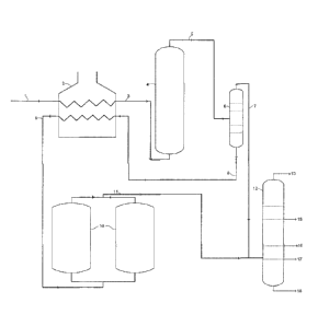
27 A schematic process flow diagram of the invented process is provided as
Fig. 1. Resid feedstock
28 (1) is heated in a furnace (2) to get the hot feed (3) at the desired
inlet temperature of the pre-
29 cracking reactor. Hot feed at desired temperature and pressure is sent
to the pre-cracking reactor
(4) which is operating at a temperature range of about 350 to 470 C and
pressure range of about
31 1 to 15 Kg/cm2, where it undergoes mild thermal cracking reactions. The
outlet product material
32 stream (5) is then sent to the intermediate separator (6) to split the
hydrocarbons into two fractions.
24359150.1
Date recue/ date received 2022-02-17
CA Application
Blokes Ref. 12364/00005
1 The top fraction (7) containing lighter products including gases are sent
to the main fractionator
2 (12). The bottom product (8) is then subjected to heating in furnace (2)
to the desired coking
3 temperature. The hot hydrocarbon stream (9) exiting the furnace is then
sent to the preheated coke
4 drum (10), where it is provided with a longer residence time for thermal
cracking reactions. The
product vapors exiting the coke drum (11) are sent to the main fractionator
(12) column for further
6 separation into desired product fractions like offgas with LPG and
naphtha (13), Kero (15), LCGO
7 (16), HCGO (17) and CFO (18). The entry points of products from
intermediate separator and
8 coke drum to the main fractionators may be suitably selected based on
good engineering practices.
9
An embodiment of the invention is provided in Fig. 2, with lesser hardware
requirement. In the
11 process scheme described in Fig.2, resid feedstock (19) is heated in a
furnace (20) to get the hot
12 feed (21) at the desired inlet temperature of the pre-cracking reactor
(22). Hot feed at desired
13 temperature and pressure is sent to the pre-cracking reactor (22), where
it undergoes mild thermal
14 cracking reactions. The outlet product material stream (23) is then sent
to the main fractionator
column (24), where the product hydrocarbons get fractionated to different
desired product
16 streams. The heavy bottom fraction is withdrawn from the main
fractionator bottom (30) and is
17 sent to the furnace (20) for heating to the desired coking temperature.
The hot hydrocarbon stream
18 (31) exiting the furnace is then sent to the preheated coke drum (32),
where it is provided with a
19 longer residence time for delayed coking reactions. The product vapors
exiting the coke drum
(33) along with product stream from pre-cracking reactor are sent to the main
fractionator (24)
21 column for further separation into desired product fractions like offgas
with LPG and naphtha
22 (25), Kero (27), LCGO (28), HCGO (29), CFO (34) and heavy bottom
fraction (30). The heavy
23 bottom fraction may be subjected to vacuum flashing to remove the
lighter material further. The
24 entry points of products from pre-cracking reactor and coke drum to the
main fractionator may be
suitably selected based on good engineering practices.
26 The embodiment as represented in Fig. 2 achieve following advantages by
directing the whole of
27 effluents from pre-cracker reactor to the main fractionator column:
28
29 1) Elimination of intermediate separator column.
2) Heat content of precracker effluent can be used for better separation in
the main fractionator as
31 with intermediate separator, one need to cool the precracker effluent
and operate intermediate
32 separator at a lower temperature.
11
24359150.1
Date recue/ date received 2022-02-17
CA Application
Blokes Ref. 12364/00005
1
2 Another embodiment of the invention is provided in Fig. 3. Resid
feedstock (35) is first sent to
3 the bottom section of the main fractionator (36) to get the hot feed (37)
mixed with the internal
4 recycle stream. The hot feed (37) is then heated in a Furnace (38) to get
the hot feed (39) at the
desired inlet temperature of the pre-cracking reactor (40). Hot feed at
desired temperature and
6 pressure is sent to the pre-cracking reactor (40), where it undergoes
mild thermal cracking
7 reactions. The outlet product material stream (41) is then sent to the
intermediate separator (42)
8 to split the hydrocarbons into two fractions. The top fraction (43)
containing lighter products
9 including gases are sent to the main fractionator (36). The bottom
product (44) is then subjected
to further heating in furnace (38) to the desired coking temperature. The hot
hydrocarbon stream
11 (45) exiting the furnace is then sent to the preheated coke drum (46),
where it is provided with a
12 longer residence time for delayed coking reactions. The product vapors
exiting the coke drum
13 (47) are sent to the main fractionator (36) column for further
separation into desired product
14 fractions like offgas with LPG and naphtha (48), Kero (50), LCGO (51),
HCGO (52) and CFO
(53). The entry points of products from pre-cracking reactor and coke drum to
the main
16 fractionator may be suitably selected based on good engineering
practices.
17
18 Yet another embodiment of the invention is provided in Fig. 4. In the
process scheme described
19 in Fig.4, resid feedstock (54) is heated in a furnace (55) to get the
hot feed (56) at the desired inlet
temperature of the pre-cracking reactor (57). Hot feed at desired temperature
and pressure is sent
21 to the pre-cracking reactor (57), where it undergoes mild thermal
cracking reactions. The outlet
22 product material stream (58) is then sent to the intermediate separator
(59). Heavier bottom
23 material (60) from the main fractionator column (61) is also put in the
intermediate separator (59).
24 Vapor products (62) separated in the intermediate separator is routed to
the main fractionator
column (61) for separation into desired products. The heavy bottom fraction
(63) is withdrawn
26 from the intermediate separator (59) and is sent to the furnace (55) for
heating
27 to the desired coking temperature. The hot hydrocarbon stream (64)
exiting the furnace is then
28 sent to the preheated coke drum (65), where it is provided with a longer
residence time for thermal
29 cracking reactions. The product vapors exiting the coke drum (66) are
sent to the main fractionator
(61) column for further separation into desired product fractions like offgas
with LPG and naphtha
31 (67), Kero (68), LCGO (69), HCGO (70) and CFO (71). The heavy bottom
fraction (60) is routed
12
24359150.1
Date recue/ date received 2022-02-17
CA Application
Blokes Ref. 12364/00005
1 to the intermediate separator (59). The entry points of products from pre-
cracking reactor and
2 coke drum to the main fractionator may be suitably selected based on good
engineering practices.
3
4 The embodiment as represented in Fig. 4 has a superior control over the
recycle ratio of the
operation of the coke drum section. By varying the quantity of the heavier
bottom material (60),
6 one can manipulate the recycle ratio to impact both coke properties and
the liquid product
7 properties. This offers a great flexibility to the refiner over product
quality.
8
9 Yet another embodiment of the invention is provided in Fig. 5. Resid
feedstock (72) is first sent
to the bottom section of the main fractionator (73) to get the hot feed (74)
mixed with the internal
11 recycle stream. The hot feed (74), along with CLO stream (75) from
FCC/RFCC is then heated in
12 a Furnace (76) to get the hot feed (77) at the desired inlet temperature
of the pre-cracking reactor
13 (78). Hot feed at desired temperature and pressure is sent to the pre-
cracking reactor (78), where
14 it undergoes mild thermal cracking reactions. The outlet product
material stream (79) is then sent
to the intermediate separator (80) to split the hydrocarbons into two
fractions. The top fraction
16 (81) containing lighter products including gases are sent to the main
fractionator (73). The bottom
17 product (82) is then subjected to further heating in furnace (76) to the
desired coking temperature.
18 The hot hydrocarbon stream (83) exiting the furnace is then sent to the
preheated coke drum (84),
19 where it is provided with a longer residence time for delayed coking
reactions. The product vapors
exiting the coke drum (85) are sent to the main fractionator (73) column for
further separation
21 into desired product fractions like offgas with LPG and naphtha (86),
Kero (87), LCGO (88),
22 HCGO (89) and CFO (90). The entry points of products from pre-cracking
reactor and coke drum
23 to the main fractionator may be suitably selected based on good
engineering practices.
24
In another embodiment, CLO stream (75) is mixed with the bottom product (82)
of the
26 intermediate separator (80) before sending to furnace (76) to produce
the hot stream (83).
27 In embodiment as represented in Fig. 5, CLO stream (75) is a
predominantly aromatic stream
28 from fluid catalytic cracking unit. Addition of this stream in the
feedstock helps in improving the
29 stability of asphaltene molecules (asphaltene molecules in the feedstock
causes coke deposition
inside the furnace tubes).
31
32 EXAMPLES:
13
24359150.1
Date recue/ date received 2022-02-17
CA Application
Blakes Ref. 12364/00005
1 Pilot scale experimental study is carried out for validating the merits
of the invented process
2 schemes. Experiments are carried out with a resid feedstock of
characteristics provided in Table-
3 1.
4 Table-1: Properties of resid feedstock
Feed characteristics Value
Density, g/cc 1.042
CCR, wt% 23.39
Asphaltene content, wt% 7.8
Sulfur, wt% 5.73
Liquid analysis (D2887/D6352) wt% Deg C
0 409
506
30 562
50 600
70 639
80 659
90 684
95 698
Metal, ppm
Fe 6
Na 47
Ca 3
Cr 1
Si 1
5
6 A base case experiment is carried out in the delayed coker pilot plant
using the resid feedstock at
7 delayed coking conditions. The operating conditions for all the
experiments are 495 C, feed
8 furnace outlet line temperature, 14.935 psig coke drum pressure, 1 wt%
steam addition to the coker
9 feed and a feed rate maintained at about 8 kg/h. The operation is carried
out in semi
10 batch mode. The vapors from the coking drums are recovered as liquid and
gas products and no
11 coker product is recycled to the coker drum. Major operating parameters
and the corresponding
12 discrete product yield pattern are provided in Table-2.
13 Table-2: Base case pilot plant experimental data with resid feedstock at
delayed coker conditions.
14
Feed characteristics Unit Value
Feed rate Kg/hr 8
14
24359150.1
Date recue/ date received 2022-02-17
CA Application
Blakes Ref. 12364/00005
Run duration Hr 12
COT C 495
Drum pressure kg/cm2 1.05
Yield (Basis: fresh feed) Unit Value
Fuel gas wt% 6.82
LPG wt% 5.66
C5-140 C wt% 9.38
140-370 C wt% 26.80
370 C+ wt% 24.40
Coke wt% 26.94
1
2 The yields obtained from the base case experiment as provided in Table-2
form the conventional
3 Delayed coker unit (DCU) process yields for the resid feedstock taken. In
order to find the yields
4 from invented process, a first experiment is carried out with the resid
feedstock of Table-1 at mild
thermal cracking conditions envisaged for the pre-cracker reactor. The major
operating parameters
6 and the corresponding discrete product yield pattern are provided in
7 Table-3.
8
24359150.1
Date recue/ date received 2022-02-17
CA Application
Blakes Ref. 12364/00005
1 Table-3: Pilot plant experimental data with resid feedstock using pre-
cracker reactor.
Process conditions Value
COT, C 444
Pre-cracker inlet temp, C 436
Pre-cracker outlet temp, C 409
Pre-cracker inlet pressure, Kg/cm2(g) 12.3
Pre-cracker outlet pressure, Kg/cm2(g) 11.9
Product yield pattern, wt% Value
Fuel gas 1.22
LPG 1.59
Cs-140 C 3.05
140-370 C 11.89
Pre-cracker bottom (370 C +) 82.25
2
3 Heavy bottom material (370 C+) generated from the pre-cracker reactor is
separated in a
4 fractionator/intermediate separator and experiment is carried out using
this material at the
conditions of delayed coking, in the delayed coker pilot plant. The major
operating parameters
6 and the corresponding discrete product yield pattern are provided in
Table-4.
7
8 Table-4: Pilot plant experimental data with heavy bottom material (370 C
+) from intermediate
9 separator at delayed coker conditions.
Process conditions Value
Run duration 12 hrs
Feed rate, Kg/hr 8
Run duration, hr 12
COT, C 495
Drum pressure, Kg/cm2(g) 1.05
Yield in wt% (Basis: fresh feed) Value
Fuel gas 7.46
LPG 5.07
C5-140 C 7.16
40-370 C 26.40
370 C + 26.09
Coke 27.82
11
16
24359150.1
Date recue/ date received 2022-02-17
CA Application
Blokes Ref. 12364/00005
1 From the experimental data as provided in Tables-3 & 4, the yields for
the invented process
2 scheme is estimated and is compared with the base case delayed coker
yields, in Table-5.
3
4 Table-5: Comparison of yields obtained in invented process and the base
case DCU yields
Invented Base case DCU Yield
process yields yields improvement
Yields Wt% Wt% AWt%
Fuel gas 7.36 6.82 +0.54
LPG 5.76 5.66 +0.10
Cs-140 C 8.94 9.38 -0.45
140-370 C 33.60 26.80 +6.80
370 C + 21.46 24.40 -2.94
Coke 22.88 26.94 -4.06
6 The experimental data reported in Table-5 shows that there is improvement
in diesel range product
7 of about 7 wt% and reduction in coke and fuel oil yields of about 4 wt%
and 3 wt% respectively
8 for the process scheme of the present invention over the conventional
delayed coking process.
9
Those of ordinary skill in the art will appreciate upon reading this
specification, including the
11 examples contained herein, that modifications and alterations to the
composition and methodology
12 for making the composition may be made within the scope of the invention
and it is intended that
13 the scope of the invention disclosed herein be limited only by the
broadest interpretation of the
14 appended claims to which the inventor is legally entitled.
17
24359150.1
Date recue/ date received 2022-02-17