Note: Descriptions are shown in the official language in which they were submitted.
81799022
1
PRODUCING POLYOLEFIN PRODUCTS
RELATED APPLICATIONS
[0001] This application claims the benefit of U.S. Provisional Patent
Applications having the
following serial numbers: Serial No. 61/938,466, by Ching-Tai Lue et al, filed
February 11,
2014 (2014U032.PRV); Serial No. 61/938,472, by Ching-Tai Lue et al., filed
February 11, 2014
(2014U003.PRV); Serial No. 61/981,291, by Francis C. Rix et al., filed April
18, 2014
(2014U010.PRV); Serial No. 61/985,151, by Francis C. Rix et al., filed April
28, 2014
(2014U012.PRV); Serial No. 62/032,383, by Sun-Chueh Kao et al., filed August
1, 2014
(2014U018.PRV); Serial No. 62/087,905, by Francis C. Rix et al., filed
December 5, 2014
(2014U035.PRV); Serial No. 62/088,196, by Daniel P. Zilker, Jr. et al., filed
December 5, 2014
(2014U036.PRV), Serial No. 62/087,911, by Ching-Tai Lue et al, filed December
5, 2014
(2014U037.PRV), and Serial No. 62J087,914, by Francis C. Rix et al., filed
December 5, 2014
(2014 U038.PRV) .
BACKGROUND
[0002] Ethylene alpha-olefin (polyethylene) copolymers are typically
produced in a low
pressure reactor, utilizing, for example, solution, slurry, or gas phase
polymerization processes.
Polymerization takes place in the presence of catalyst systems such as those
employing, for
example, a Ziegler-Natta catalyst, a chromium based catalyst, a metallocene
catalyst, or
combinations thereof.
[0003] A number of catalyst compositions containing single site, e.g.,
metallocene, catalysts
have been used to prepare polyethylene copolymers, producing relatively
homogeneous
copolymers at good polymerization rates. In contrast to traditional Ziegler-
Natta catalyst
compositions, single site catalyst compositions, such as metallocene
catalysts, are catalytic
compounds in which each catalyst molecule contains one or only a few
polymerization sites.
Single site catalysts often produce polyethylene copolymers that have a narrow
molecular
weight distribution. Although there are single site catalysts that can produce
broader molecular
weight distributions, these catalysts often show a narrowing of the molecular
weight distribution
as the reaction temperature is increased, for example, to increase production
rates. Further, a
single site catalyst will often incorporate comonomer among the molecules of
the polyethylene
copolymer at a relatively uniform rate. The molecular weight distribution and
the amount of
comonomer incorporation can be used to determine a composition distribution.
Date Recue/Date Received 2021-08-10
CA 02938846 2016-08-04
WO 2015/123179 PCMJS2015/015143
2
[0004] The composition distribution of an ethylene alpha-olefin copolymer
refers to the
distribution of comonomer, which form short chain branches, among the
molecules that
comprise the polyethylene polymer. When the amount of short chain branches
varies among the
polyethylene molecules, the resin is said to have a "broad" composition
distribution. When the
amount of comonomer per 1000 carbons is similar among the polyethylene
molecules of
different chain lengths, the composition distribution is said to be "narrow".
[0005] The composition distribution is known to influence the properties of
copolymers, for
example, stiffness, toughness, extracTable content, environmental stress crack
resistance, and
heat sealing, among other properties. The composition distribution of a
polyolefin may be
readily measured by methods known in the art, for example, Temperature Raising
Elution
Fractionation (TREF) or Crystallization Analysis Fractionation (CRYSTAF).
[0006] It is generally known in the art that a polyolefin's composition
distribution is largely
dictated by the type of catalyst used and is typically invariable for a given
catalyst system.
Ziegler-Natta catalysts and chromium based catalysts produce resins with broad
composition
distributions (BCD), whereas metallocene catalysts normally produce resins
with narrow
composition distributions (NCD).
[0007] Resins having a broad orthogonal composition distribution (BOCD) in
which the
comonomer is incorporated predominantly in the high molecular weight chains
can lead to
improved physical properties, for example toughness properties and
environmental stress crack
resistance (ESCR). Because of the improved physical properties of resins with
orthogonal
composition distributions needed for commercially desirable products, there
exists a need for
controlled techniques for forming polyethylene copolymers having a broad
orthogonal
composition distribution.
SUMMARY
[0008] An exemplary embodiment described herein provides a method of
selecting catalysts
for making a product specific polyolefin using a blend polydispersity index
(bPDI) map. The
method includes generating a number of polymers for at least two catalysts,
wherein each
polymer is generated at a different hydrogen to ethylene ratio. One of the
catalysts generates a
higher molecular weight (hmw) polymer and another of the at least two
catalysts generates a
lower molecular weight (lmw) polymer. The weight averaged molecular weight and
PDI is
measured for each polymer. The relationship between the molecular weight of
the polymers
generated by each of the at least two catalysts and the ratio of hydrogen to
ethylene is generated.
A family of bPDI curves for polymers that would be made using a number of
ratios of a blend of
81799022
3
the at least two catalysts for each of a number of ratios of hydrogen to
ethylene is generated. A
ratio for a blend of the catalysts is selected that generates a polymer having
a bPDI that matches
a polymer fabrication process. The ratio of the catalysts is confirmed by
generating a polymer at
each of the number of ratios of hydrogen to ethylene.
[0009] Another exemplary embodiment provides a method of making a product
specific
polyolefin. The method includes selecting a catalyst blend based, at least in
part, on a
polydispersity index (PDI) map. The polydispersity map is generated by
generating a number of
polymers for at least two catalysts, wherein each polymer is generated at a
different hydrogen to
ethylene ratio. At least one of the catalysts generates a higher molecular
weight polymer and
another of the catalysts generates a lower molecular weight polymer. The
molecular weight is
measured for each polymer. The relationship between the molecular weight of
the polymers
generated by each of the at least two catalysts and the ratio of hydrogen to
ethylene is
determined. A family of bPDI curves for polymers that would be made using a
number of ratios
of a blend of the catalysts for each of a number of ratios of hydrogen to
ethylene is generated. A
ratio for the catalyst blend of the at least two catalysts that generates a
polymer having a bPDI
that matches a polymer fabrication process is selected. The product specific
polyolefin is
generated using the catalyst blend.
[0010] Another exemplary embodiment provides a polymerization catalyst for
forming a
polyethylene copolymer. The polymerization catalyst includes a catalyst
support and a blend of
at least two catalysts. The catalysts are selected by generating a number of
polymers for the
catalysts, wherein each polymer is generated at a different hydrogen to
ethylene ratio. One of the
catalysts generates a polymer with a higher weight average molecular weight
(hmw) and another
of the catalysts generates a polymer with a lower weight average molecular
weight (lmw). The
ratio of hmw to lmw is greater than about 5.0 at a weight average molecular
weight of between
about 30,000 and about 150,000. The molecular weight is measured for each
polymer and the
relationship between the molecular weight of the polymers generated by each of
the at least two
catalysts and the ratio of hydrogen to ethylene is determined. A family of
bPDI curves for
polymers that would be made using a number of ratios of a blend of the
catalysts for each of a
number of ratios of hydrogen to ethylene is generated. A ratio for the
catalyst blend of the
Date Recue/Date Received 2021-08-10
81799022
3a
catalysts that generates a polymer having a bPDI that matches a polymer
fabrication process is
selected.
[0010a] In some embodiments, a catalyst impregnated on the catalyst support is
bis(n-butyl,
methyl cyclopentadienyl) zirconium (CH3)2, bis(n-butyl, methyl
cyclopentadienyl) zirconium
C12, bis(n-butyl, methyl cyclopentadienyl) zirconium F2, or any combinations
thereof. In some
embodiments, a catalyst impregnated on the catalyst support is bis(1-
ethylindenyl) zirconium
(CH3)2, bis(1-ethylindenyl) zirconium F2, bis(1-ethylindenyl) zirconium C12,
or any combinations
thereof.
[0011] Another exemplary embodiment provides a polymerization catalyst for
forming a
polyethylene copolymer. The polymerization catalyst includes a catalyst
support and a first
catalyst that is impregnated on the catalyst support, wherein the first
catalyst generates polymers
Date Recue/Date Received 2021-08-10
CA 02938846 2016-08-04
WO 2015/123179 PCT/US2015/015143
4
having a slope for a plot of H2/C7 versus 1/Mw of between about 1.0x10⁻⁶ and
about 1.5 x10⁻⁶,
and wherein at a C6/C2 ratio of between about 0.008 and about 0.012. The first
catalyst
generates a polymer having an MI of about 1.0 dg/10 min, a density of about
0.92 glee, and an
melt index ratio (MIR) less than about 25. A second catalyst is impregnated on
the catalyst
support with the first catalyst, wherein the second catalyst generates
polymers having a slope
for a plot of H2/C2 versus 1/Mw of between about 3.0x10⁻⁶ and about 4 x10⁻⁶,
and wherein at a
C6/C2 ratio of between about 0.03 and about 0.04, the second catalyst
generates a polymer
having an MI of about 1.0 dg/10 min, a density of about 0.92 g/cc, and an melt
index ratio
(MIR) less than about 25.
BRIEF DESCRIPTION OF THE DRAWINGS
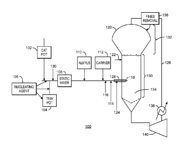
[0012] Fig. 1 is a schematic of a gas-phase reactor system, showing the
addition of at least
two catalysts, at least one of which is added as a trim catalyst.
[0013] Fig. 2 is a plot of a series of polymers that were prepared to test
the relative abilities
of a series of metallocene catalysts to prepare a resin having about a 1 melt
index (MI) and a
density (D) of about 0.92.
[0014] Fig. 3 is a plot of the series of polymers of Fig. 2, showing the
melt index ratio (MIR)
of the series of polymers made by different metallocene (MCN) catalysts.
[0015] Fig. 4 is a flow chart of a method for making a co-supported
polymerization catalyst.
[0016] Figs. 5A, 5B, and 5C are log plots of the inverse of the molecular
weight to the H2/C2
ratio for each of the hypothetical combinations.
[0017] Figs. 6A, 6B, and 6C are plots of the hydrogen response for each of
the catalysts.
[0018] Figs. 7A, 7B, and 7C are bPDI maps generated for polymers produced
by the catalyst
blend.
[0019] Fig. 8 is a process flow diagram of a method for using a bPDI map to
assist in
forming a polymer.
[0020] Fig. 9 is a process flow diagram of a method 900 for selecting a
catalyst blend, e.g.,
at block 802 of Fig. 8.
DETAILED DESCRIPTION
[0021] It has been discovered that when a support is impregnated with
multiple catalysts,
new polymeric materials with an improved balance of stiffness, toughness and
processibility can
be achieved, e.g., by controlling the amounts and types of catalysts present
on the support. As
described in embodiments herein, an appropriate selection of the catalysts and
ratios may be
CA 02938846 2016-08-04
WO 2015/123179 PCT/US2015/015143
used to adjust the molecular weight distribution (MWD), short chain branch
distribution
(SCBD), and long-chain branch distribution (LCBD) of the polymer, for example,
to provide a
polymer with a broad orthogonal composition distribution (BOCD). The MWD,
SCBD, and
LCBDs would be controlled by combining catalysts with the appropriate weight
average
molecular weight (Mw), comonomer incorporation, and long chain branching (LCB)
formation
under the conditions of the polymerization.
[0022] Employing multiple pre-catalysts that are co-supported on a single
support mixed
with an activator, such as a silica methylaluminoxane (SMAO), can provide a
cost advantage by
making the product in one reactor instead of multiple reactors. Further, using
a single support
also ensures intimate mixing of the polymers and offers improved operability
relative to
preparing a mixture of polymers of different Mw and density independently from
multiple
catalysts in a single reactor. As used herein, a pre-catalyst is a catalyst
compound prior to
exposure to activator.
[0023] As an example, for linear low-density polyethylene film (LLDPE) film
applications,
it would be desirable to prepare an ethylene hexene copolymer with a molecular
weight of
between about 90 Kg/mol and 110 Kg/mol, or about 100 Kg/mol and an average
density of
between about 0.9 and 0.925, or about 0.918. The typical MWD for linear
metallocene resins is
2.5 - 3.5. Blend studies indicate that it would be desirable to broaden this
distribution by
employing two catalysts that each provides different average molecular
weights. The ratio of
the Mw for the low molecular weight component and the high molecular weight
component
would be between 1:1 and 1:10, or about 1:2 and 1:5.
[0024] The density of a polyethylene copolymer provides an indication of
the incorporation
of comonomer into a polymer, with lower densities indicating higher
incorporation. The
difference in the densities of the low molecular weight (LMW) component and
the high
molecular weight (HMW) component would preferably be greater than about 0.02,
or greater
than about 0.04 with the HMW component having a lower density than the LMW
component.
For two resins with Mw of 25 Kg/mol and 125 Kg/mol, the difference in density
requires around
a 1.5:1 or preferably about 2:1, or more preferably about 3:1 or more
preferably a 4:1 or even a
greater than 4:1 difference in comonomer incorporation ability. It is also
desirable to minimize
the level of long chain branching (LCB) in the polymer as that provides strong
orientation in
film fabrication which imbalances MD/TD tear and reduces toughness.
[0025] These factors can be adjusted by controlling the MWD and SCBD,
which, in turn,
can be adjusted by changing the relative amount of the two pre-catalysts on
the support. This
may be adjusted during the formation of the pre-catalysts, for example, by
supporting two
CA 02938846 2016-08-04
WO 2015/123179 PCT/US2015/015143
6
catalysts on a single support. In some embodiments, the relative amounts of
the pre-catalysts
can be adjusted by adding one of the components to a catalyst mixture en-route
to the reactor in
a process termed "trim". Feedback of polymer property data can be used to
control the amount
of catalyst addition. Metallocenes (MCNs) are known to trim well with other
catalysts.
[0026] Further, a variety of resins with different MWD, SCBD, and LCBD may
be prepared
from a limited number of catalysts. To perform this function, the pre-
catalysts should trim well
onto activator supports. Two parameters that benefit this are solubility in
alkane solvents and
rapid supportation on the catalyst slurry en-route to the reactor. This favors
the use of MCNs to
achieve controlled MWD, SCBD, and LCBD. Techniques for selecting catalysts
that can be
used to generate targeted molecular weight compositions, including BOCD
polymer systems, are
disclosed herein.
[0027] Various catalyst systems and components may be used to generate the
polymers and
molecular weight compositions disclosed. These are discussed in the sections
to follow. The
first section discusses catalyst compounds that can be used in embodiments.
The second section
discusses generating catalyst slurrys that may be used for implementing the
techniques
described. The third section discusses catalyst supports that may be used. The
fourth section
discusses catalyst activators that may be used. The fifth section discusses
the catalyst
component solutions that may be used to add additional catalysts in trim
systems. Gas phase
polymerizations may use static control or continuity agents, which are
discussed in the sixth
section. A gas-phase polymerization reactor with a trim feed system is
discussed in the seventh
section. The use of the catalyst composition to control product properties is
discussed in an
eighth section and an exemplary polymerization process is discussed in a ninth
section.
Examples of the implementation of the procedures discussed is incorporated
into a tenth section.
[0028] Catalyst Compounds
[0029] Metallocene Catalyst Compounds
[0030] Metallocene catalyst compounds can include "half sandwich" and/or
"full sandwich"
compounds having one or more Cp ligands (cyclopentadienyl and ligands isolobal
to
cyclopentadienyl) bound to at least one Group 3 to Group 12 metal atom, and
one or more
leaving group(s) bound to the at least one metal atom. As used herein, all
reference to the
Periodic Table of the Elements and groups thereof is to the NEW NOTATION
published in
HAWLEY'S CONDENSED CHEMICAL DICTIONARY, Thirteenth Edition, John Wiley &
Sons, Inc., (1997) (reproduced there with permission from IUPAC), unless
reference is made to
the Previous IUPAC form noted with Roman numerals (also appearing in the
same), or unless
otherwise noted.
CA 02938846 2016-08-04
WO 2015/123179 PCT/US2015/015143
7
[0031] The Cp ligands are one or more rings or ring system(s), at least a
portion of which
includes it-bonded systems, such as cycloalkadienyl ligands and heterocyclic
analogues. The
ring(s) or ring system(s) typically include atoms selected from the group
consisting of Groups
13 to 16 atoms, and, in a particular exemplary embodiment, the atoms that make
up the Cp
ligands are selected from the group consisting of carbon, nitrogen, oxygen,
silicon, sulfur,
phosphorous, germanium, boron, aluminum, and combinations thereof, where
carbon makes up
at least 50 ')/0 of the ring members. In a more particular exemplary
embodiment, the Cp ligand(s)
are selected from the group consisting of substituted and unsubstituted
cyclopentadienyl ligands
and ligands isolobal to cyclopentadienyl, non-limiting examples of which
include
cyclopentadienyl, indenyl, fluorenyl and other structures. Further non-
limiting examples of such
ligands include cyclopentadienyl, cyclopentaphenanthreneyl, indenyl,
benzindenyl, fluorenyl,
octahydrofluorenyl, cyclooctatetraenyl, cyclopentacyclododecene,
phenanthrindenyl, 3,4-
benzofluorenyl, 9-phenylfluorenyl, 8-H-cyclopent[a]acenaphthylenyl, 7-H-
dibenzofluorenyl,
indeno[1,2-9]anthrene, thiophenoindenyl, thiophenofluorenyl, hydrogenated
versions thereof
(e.g., 4,5,6,7-tetrahydroindenyl, or "H4 Ind"), substituted versions thereof
(as discussed and
described in more detail below), and heterocyclic versions thereof.
[0032] The metal atom "M" of the metallocene catalyst compound can be
selected from the
group consisting of Groups 3 through 12 atoms and lanthanide Group atoms in
one exemplary
embodiment; and selected from the group consisting of Groups 3 through 10
atoms in a more
particular exemplary embodiment, and selected from the group consisting of Sc,
Ti, Zr, Hf, V,
Nb, Ta, Mn, Re, Fe, Ru, Os, Co, Rh, Ir, and Ni in yet a more particular
exemplary embodiment;
and selected from the group consisting of Groups 4, 5, and 6 atoms in yet a
more particular
exemplary embodiment, and Ti, Zr, Hf atoms in yet a more particular exemplary
embodiment,
and Hf in yet a more particular exemplary embodiment. The oxidation state of
the metal atom
"M" can range from 0 to +7 in one exemplary embodiment; and in a more
particular exemplary
embodiment, can be +1, +2, +3, +4, or +5; and in yet a more particular
exemplary embodiment
can be +2, +3 or +4. The groups bound to the metal atom "M" are such that the
compounds
described below in the formulas and structures are electrically neutral,
unless otherwise
indicated. The Cp ligand forms at least one chemical bond with the metal atom
M to form the
"metallocene catalyst compound." The Cp ligands are distinct from the leaving
groups bound to
the catalyst compound in that they are not highly susceptible to
substitution/abstraction
reactions.
[0033] The one or more metallocene catalyst compounds can be represented by
the formula
CA 02938846 2016-08-04
WO 2015/123179 PCT/US2015/015143
8
CpACIPMXii (1)
in which M is as described above; each X is chemically bonded to M; each Cp
group is
chemically bonded to M; and n is 0 or an integer from 1 to 4, and either 1 or
2 in a particular
exemplary embodiment.
[0034] The ligands represented by CpA and Cp13 in formula (I) can be the
same or different
cyclopentadienyl ligands or ligands isolobal to cyclopentadienyl, either or
both of which can
contain heteroatoms and either or both of which can be substituted by a group
R. In at least one
specific embodiment, CPA and Cp13 are independently selected from the group
consisting of
cyclopentadienyl, indenyl, tetrahydroindenyl, fluorenyl, and substituted
derivatives of each.
[0035] Independently, each CPA and CpB of formula (I) can be unsubstituted
or substituted
with any one or combination of substituent groups R. Non-limiting examples of
substituent
groups R as used in structure (1) as well as ring substituents in structures
Va-d, discussed and
described below, include groups selected from the group consisting of hydrogen
radicals, alkyls,
alkenyls, alkynyls, cycloalkyls, aryls, acyls, aroyls, alkoxys, aryloxys,
alkylthiols,
dialkylamines, alkylamidos, alkoxycarbonyls, aryloxycarbonyls, carbomoyls,
alkyl- and dialkyl-
carbamoyls, acyloxys, acylaminos, aroylaminos, and combinations thereof. More
particular
non-limiting examples of alkyl substituents R associated with formulas (I)
through (Va-d)
include methyl, ethyl, propyl, butyl, pentyl, hexyl, cyclopentyl, cyclohexyl,
benzyl, phenyl,
methylphenyl, and tert-butylphenyl groups and the like, including all their
isomers, for example,
tertiary-butyl, isopropyl, and the like.
[0036] As used herein, and in the claims, hydrocarbyl substituents, or
groups, are made up
of between 1 and 100 or more carbon atoms, the remainder being hydrogen. Non-
limiting
examples of hydrocarbyl substituents include linear or branched or cyclic:
alkyl radicals; alkcnyl
radicals; alkynyl radicals; cycloalkyl radicals; aryl radicals; alkylene
radicals, or a combination
thereof. Non-limiting examples include methyl, ethyl, propyl, butyl, pentyl,
hexyl, cyclopentyl,
cyclohexyl; olefinically unsaturated substituents including vinyl-terminated
ligands (for example
but-3-enyl, prop-2-enyl, hex-5-enyl and the like), benzyl or phenyl groups and
the like,
including all their isomers, for example tertiary butyl, isopropyl, and the
like.
[0037] As used herein, and in the claims, substituted hydrocarbyl
substituents, or groups, are
made up of between 1 and 100 or more carbon atoms, the remainder being
hydrogen, fluorine,
chlorine, bromine, iodine, oxygen, sulfur, nitrogen, phosphorous, boron,
silicon, germanium or
tin atoms or other atom systems tolerant of olefin polymerization systems.
Substituted
hydrocarbyl substituents are carbon based radicals. Non-limiting examples of
substituted
hydrocarbyl substituents trifluoromethyl radical_ trimethylsilanemethyl
(Me3SiCH 2-) radicals.
CA 02938846 2016-08-04
WO 2015/123179 PCT/US2015/015143
9
[0038] As used herein, and in the claims, heteroatom substituents, or
groups, are fluorine,
chlorine, bromine, iodine, oxygen, sulfur, nitrogen, phosphorous, boron,
silicon, germanium or
tin based radicals. They may be the heteroatom atom by itself. Further,
heteroatom substituents
include organometalloid radicals. Non-limiting examples of heteroatom
substituents include
chloro radicals, fluoro radicals, methoxy radicals, diphenyl amino radicals,
thioalkyls,
thioalkenyls, trimethylsilyl radicals, dimethyl aluminum radicals,
alkoxydihydrocarbylsilyl
radicals, siloxydiydrocabylsilyl radicals, tris(perflourophenyOboron and the
like.
[0039] Other possible radicals include substituted alkyls and aryls such
as, for example,
fluoromethyl, fluroethyl, difluroethyl, iodopropyl, bromohexyl, chlorobenzyl,
hydrocarbyl
substituted organometalloid radicals including trimethylsilyl,
trimethylgermyl,
methyldiethylsilyl, and the like, and halocarbyl-substituted organometalloid
radicals, including
tris(trifluoromethyl)silyl, methylbis(difluoromethyl)silyl,
bromomethyldimethylgermyl and the
like; and disubstituted boron radicals including dimethylboron, for example;
and disubstituted
Group 15 radicals including dimethylamine, dimethylphosphine, diphenylamine,
methylphenylphosphine, as well as Group 16 radicals including methoxy, ethoxy,
propoxy,
phenoxy, methylsulfide and ethylsulfide. Other substituent groups R include,
but are not limited
to, olefins such as olefinically unsaturated substituents including vinyl-
terminated ligands such
as, for example, 3-butenyl, 2-propenyl, 5-hexenyl, and the like. In one
exemplary embodiment,
at least two R groups (two adjacent R groups in a particular exemplary
embodiment) are joined
to form a ring structure having from 3 to 30 atoms selected from the group
consisting of carbon,
nitrogen, oxygen, phosphorous, silicon, germanium, aluminum, boron, and
combinations
thereof. Also, a substituent group R such as 1-butanyl can form a bonding
association to the
element M.
[0040] Each X in the formula (I) above and for the formula/structures (II)
through (Va-d)
below is independently selected from the group consisting of: any leaving
group, in one
exemplary embodiment; halogen ions, hydrides, C1 to C12 alkyls, C2 to CP
alkenyls, C6 to CP
aryls, C7 to C20 alkylaryls, C1 to C12 alkoxys, C6 to C16 aryloxys, C7 to C8
alkylaryloxys, C1 to
C12 fluoroalkyls, C6 to C12 fluoroaryls, and CI to C12 heteroatom-containing
hydrocarbons and
substituted derivatives thereof, in a more particular exemplary embodiment;
hydride, halogen
ions, CI to C6 alkyls, C? to C6 alkenyls, C7 to Cis alkylaryls, CI to C6
alkoxys, Co to C14
aryloxys, C7 to C16 alkylaryloxys, C1 to C6 alkylcarboxyla yield a new
polymerization catalyst
tes, C1 to C6 fluorinated alkylcarboxylates, C6 to C12 arylcarboxylates, C7 to
C18
alkylarylcarboxylates, Ci to C6 fluoroalkyls, C2 to C6 fluoroalkenyls, and C7
to C18
fluoroalkylaryls in yet a more particular exemplary embodiment; hydride,
chloride, fluoride,
CA 02938846 2016-08-04
WO 2015/123179 PCT/US2015/015143
methyl, phenyl, phenoxy, benzoxy, tosyl, fluoromethyls and fluorophenyls, in
yet a more
particular exemplary embodiment; C1 to C12 alkyls, C2 to C12 alkenyls, C6 to
C12 aryls, C7 to Czo
alkylaryls, substituted C1 to C12 alkyls, substituted C6 to C12 aryls,
substituted C7 to C20
alkylaryls and C1 to C12 heteroatom-containing alkyls, C1 to Cu heteroatom-
containing aryls,
and C1 to C12 heteroatom-containing alkylaryls, in yet a more particular
exemplary embodiment;
chloride, fluoride, Ci to C6 alkyls, C2 to C6 alkenyls, C7 to C18 alkylaryls,
halogenated Ci to C6
alkyls, halogenated C2 to C6 alkenyls, and halogenated C7 to C18 alkylaryls,
in yet a more
particular exemplary embodiment; fluoride, methyl, ethyl, propyl, phenyl,
methylphenyl,
dimethylphenyl, trimethylphenyl, fluoromethyls (mono-, di- and
trifluoromethyls) and
fluorophenyls (mono-, di-, tri-, tetra- and pentafluorophenyls), in yet a more
particular
exemplary embodiment; and fluoride, in yet a more particular exemplary
embodiment.
[0041] Other non-limiting examples of X groups include amines, phosphincs,
ethers,
carboxylates, dienes, hydrocarbon radicals having from 1 to 20 carbon atoms,
fluorinated
hydrocarbon radicals (e.g., -C6F5 (pentafluorophenyl)), fluorinated
alkylcarboxylates (e.g.,
CF3C(0)0-), hydrides, halogen ions and combinations thereof. Other examples of
X ligands
include alkyl groups such as cyclobutyl, cyclohexyl, methyl, heptyl, tolyl,
trifluoromethyl,
tetramethylene, pentamethylene, methylidene, methyoxy, ethyoxy, propoxy,
phenoxy, bis(N-
methylanilide), dimethylamide, dimethylphosphide radicals and the like. In one
exemplary
embodiment, two or more X's form a part of a fused ring or ring system. In at
least one specific
embodiment, X can be a leaving group selected from the group consisting of
chloride ions,
bromide ions, C1 to C10 alkyls, and C2 to C17 alkenyls, carboxylates,
acetylacetonates, and
alkoxides.
[0042] The metallocenc catalyst compound includes those of formula (I)
where CPA and Cp8
are bridged to each other by at least one bridging group, (A), such that the
structure is
represented by formula (II):
CpA(A)Cp8MXn (II)
These bridged compounds represented by formula (II) are known as "bridged
metallocenes."
The elements CpA, CpB, M, X and n in structure (II) are as defined above for
formula (I); where
each Cp ligand is chemically bonded to M, and (A) is chemically bonded to each
Cp. The
bridging group (A) can include divalent hydrocarbon groups containing at least
one Group 13 to
16 atom, such as, but not limited to, at least one of a carbon, oxygen,
nitrogen, silicon,
aluminum, boron, germanium, tin atom, and combinations thereof; where the
heteroatom can
also be C1 to Cu alkyl or aryl substituted to satisfy neutral valency. In at
least one specific
embodiment, the bridging group (A) can also include substituent groups R as
defined above (for
CA 02938846 2016-08-04
WO 2015/123179 PCT/US2015/015143
11
formula (I)) including halogen radicals and iron. In at least one specific
embodiment, the
bridging group (A) can be represented by Ci to C6 alkylenes, substituted C1 to
C6 alkylenes,
oxygen, sulfur, R'2C=, R'?Si=, =Si(W),Si(R` 2 )=, R'2Ge=, and R'P=, where "=÷
represents two
chemical bonds, R' is independently selected from the group consisting of
hydride, hydrocarbyl,
substituted hydrocarbyl, halocarbyl, substituted halocarbyl, hydrocarbyl-
substituted
organometalloid, halocarbyl-substituted organometalloid, disubstituted boron,
disubstituted
Group 15 atoms, substituted Group 16 atoms, and halogen radical; and where two
or more R'
can be joined to form a ring or ring system. In at least one specific
embodiment, the bridged
metallocene catalyst compound of formula (II) includes two or more bridging
groups (A). In
one or more embodiments, (A) can be a divalent bridging group bound to both
CPA and CpB
selected from the group consisting of divalent CI to C20 hydrocarbyls and CI
to C20 heteroatom
containing hydrocarbonyls, where the heteroatom containing hydrocarbonyls
include from one
to three heteroatoms.
[0043] The
bridging group (A) can include methylene, ethylene, ethylidene, propylidene,
isopropylidene, diphenylmethylene, 1,2-dimethylethylene, 1,2-diphenylethylene,
1,1,2,2-
tetramethylethylene, dimethylsilyl, diethylsilyl, methyl-ethylsilyl,
trifluoromethylbutylsilyl,
bis(trifluoromethyl)silyl, di(n-butyl)silyl, di(n-propyl)silyl, di(i-
propyl)silyl, di(n-hexyl)silyl,
dicyclohexylsilyl, diphenylsilyl,
cyclohexylphenylsilyl, t-butylcyclohexylsilyl,
di(t-butylphenyl)silyl, di(p-tolyl)silyl,and the corresponding moieties where
the Si atom is
replaced by a Ge or a C atom; as well as dimethylsilyl, diethylsilyl,
dimethylgermyl and
diethylgermyl. The bridging group (A) can also include ¨Si(hydrocarby02-0-
(hydrocarby1)2Si-
-Si(substitutedhydrocarby02-0-(substitutedhydrocarby1)2Si- groups and the like
such as ¨
SiMe2-0-SiMe2- and ¨SiPh2-0-SiPh2-.
[0044] The
bridging group (A) can also be cyclic, having, for example, 4 to 10 ring
members; in a more particular exemplary embodiment, bridging group (A) can
have 5 to 7 ring
members. The ring members can be selected from the elements mentioned above,
and, in a
particular embodiment, can be selected from one or more of B, C, Si, Ge, N,
and 0. Non-
limiting examples of ring structures which can be present as, or as part of,
the bridging moiety
are cyclobutylidene, cyclopentylidene, cyclohexylidene, cycloheptylidene,
cyclooctylidene and
the corresponding rings where one or two carbon atoms are replaced by at least
one of Si, Ge, N
and 0. In one or more embodiments, one or two carbon atoms can be replaced by
at least one of
Si and Ge. The bonding arrangement between the ring and the Cp groups can be
cis-, trans-, or
a combination thereof.
CA 02938846 2016-08-04
WO 2015/123179 PCT/US2015/015143
12
[0045] The cyclic bridging groups (A) can be saturated or unsaturated
and/or can carry one
or more substituents and/or can be fused to one or more other ring structures.
If present, the one
or more substituents can be, in at least one specific embodiment, selected
from the group
consisting of hydrocarbyl (e.g., alkyl, such as methyl) and halogen (e.g., F,
Cl). The one or
more Cp groups to which the above cyclic bridging moieties can optionally be
fused can be
saturated or unsaturated, and are selected from the group consisting of those
having 4 to 10,
more particularly 5, 6, or 7 ring members (selected from the group consisting
of C, N, 0, and S
in a particular exemplary embodiment) such as, for example, cyclopentyl,
cyclohexyl and
phenyl. Moreover, these ring structures can themselves be fused such as, for
example, in the
case of a naphthyl group. Moreover, these (optionally fused) ring structures
can carry one or
more substituents. Illustrative, non-limiting examples of these substituents
are hydrocarbyl
(particularly alkyl) groups and halogen atoms. The ligands CPA and Cp13 of
formula (I) and (II)
can be different from each other. The ligands CPA and Cp8 of formula (I) and
(II) can be the
same. The metallocene catalyst compound can include bridged mono-ligand
metallocene
compounds (e.g., mono cyclopentadienyl catalyst components).
[0046] It is contemplated that the metallocene catalyst components
discussed and described
above include their structural or optical or enantiomeric isomers (racemic
mixture), and, in one
exemplary embodiment, can be a pure enantiomer. As used herein, a single,
bridged,
asymmetrically substituted metallocene catalyst compound having a racemic
and/or mcso
isomer does not, itself, constitute at least two different bridged,
metallocene catalyst
components.
[0047] As noted above, the amount of the transition metal component of the
one or more
metallocene catalyst compounds in the catalyst system can range from a low of
about 0Ø01 wt.
%, about 0.2 wt %, about 3 wt. %, about 0.5 wt. %, or about 0.7 wt. % to a
high of about 1 wt.
%, about 2 wt. %, about 2.5 wt. %, about 3 wt. %, about 3.5 wt. %, or about 4
wt. %, based on
the total weight of the catalyst system.
[0048] The "metallocene catalyst compound" can include any combination of
any
"embodiment" discussed and described herein. For example, the metallocene
catalyst
compound can include, but is not limited to, bis(n-propylcyclopentadienyl)
hafnium (CH3)2,
bis(n-propylcyclopentadienyl) hafnium F,, bis(n-propylcyclopentadienyl)
hafnium C12, or bis(n-
butyl, methyl cyclopentadienyl) zirconium C12, or any combination thereof.
[0049] Other metallocene catalyst compounds that may be used are supported
constrained
geometry catalysts (sCGC) that include (a) an ionic complex, (b) a transition
metal compound,
(c) an organometal compound, and (d) a support material. In some embodiments,
the sCGC
CA 02938846 2016-08-04
WO 2015/123179 PCT/US2015/015143
13
catalyst may include a borate ion. The borate anion is represented by the
formula [BQ4,z,(Gq(T--
H),),.]d-, wherein: B is boron in a valence state of 3; Q is selected from the
group consisting of
hydride, dihydrocarbylamido, halide, hydrocarbyloxide, hydrocarbyl, and
substituted-
hydrocarbyl radicals; z' is an integer in a range from 1 to 4; G is a
polyvalent hydrocarbon
radical having r+1 valencies bonded to M' and r groups (T--H); q is an
integer, 0 or 1; the group
(T--H) is a radical wherein T includes 0, S, NR, or PR, the 0, S, N or P atom
of which is
bonded to hydrogen atom H, wherein R is a hydrocarbyl radical, a
trihydrocarbylsilyl radical, a
trihydrocarbyl germyl radical or hydrogen; r is an integer from 1 to 3; and d
is 1. Alternatively
the borate ion may be representative by the formula [BQ4,(Gq(T--
M0Rcx_iXay)r)zid , wherein: B
is boron in a valence state of 3; Q is selected from the group consisting of
hydride,
dihydrocarbylamido, halide, hydrocarbyloxide, hydrocarbyl, and substituted-
hydrocarbyl
radicals; z' is an integer in a range from 1 to 4; G is a polyvalent
hydrocarbon radical having r+1
valencies bonded to B and r groups (T--M Rcx_iry); q is an integer, 0 or 1;
the group (T--
M Rcx_iXay) is a radical wherein T includes 0, S, NR, or PR, the 0, S, N or P
atom of which is
bonded to M , wherein R is a hydrocarbyl radical, a trihydrocarbylsilyl
radical, a trihydrocarbyl
germyl radical or hydrogen; M is a metal or metalloid selected from Groups 1-
14 of the
Periodic Table of the Elements, Rc independently each occurrence is hydrogen
or a group having
from 1 to 80 nonhydrogen atoms which is hydrocarbyl, hydrocarbylsilyl, or
hydrocarbylsilylhydrocarbyl; Xa is a noninterfering group having from 1 to 100
nonhydrogen
atoms which is halo-substituted hydrocarbyl, hydrocarbylamino-substituted
hydrocarbyl,
hydrocarbyloxy-substituted hydrocarbyl,
hydrocarbylamino, di(hydrocarbyl)amino,
hydrocarbyloxy or halide; x is a nonzero integer which may range from 1 to an
integer equal to
the valence of M ; y is zero or a nonzero integer which may range from 1 to an
integer equal to 1
less than the valence of M ; and x+y equals the valence of M ; r is an integer
from 1 to 3; and d
is 1. In some embodiments, the borate ion may be of the above described
formulas where z' is 1
or 2, q is 1, and r is 1.
[0050] The
catalyst system can include other single site catalysts such as Group 15-
containing catalysts. The catalyst system can include one or more second
catalysts in addition to
the single site catalyst compound such as chromium-based catalysts, Ziegler-
Natta catalysts, one
or more additional single-site catalysts such as metallocenes or Group 15-
containing catalysts,
bimetallic catalysts, and mixed catalysts. The catalyst system can also
include A1C13, cobalt,
iron, palladium, or any combination thereof.
CA 02938846 2016-08-04
WO 2015/123179 PCT/US2015/015143
14
[0051] Examples
of structures of MCN compounds that may be used in embodiments
include the hafnium compound shown as formula (III), the zirconium compounds
shown as
formulas (IV-A-C), and bridged zirconium compounds, shown as formulas (V-A-B).
Pr Et
Et
HfMe2 ZrMe2 ZrMe2
Pr
Et Et
(III), (IV-A), (IV-B),
Me2 Me2Si ()11111111b; '
ZrMe2 Me Zr
ZrCl2
l/-M11111W4 '1111W1 Me2Si CLAW
Me (W-C), Me (IV-D),
(V-A), or
Me2Si z ZrCl2
t-Bu (V-B)
Although these compounds are shown with methyl- and chloro- groups attached to
the central
metal, it can be understood that these groups may be different without
changing the catalyst
involved. For example, each of these substituents may independently be a
methyl group (Me), a
chloro group (Cl), a fluoro group (F), or any number of other groups,
including organic groups,
or heteroatom groups. Further, these substituents will change during the
reaction, as a pre-
catalyst is converted to the active catalyst for the reaction. Further, any
number of other
substituents may be used on the ring structures, including any of the
substituents described
above with respect to formulas (I) and (II).
[0052] Group 15 Atom and Metal-
Containing Catalyst Compounds
[0053] The
catalyst system can include one or more Group 15 metal-containing catalyst
compounds, such as [(2,3,4,5,6 Me5C6N)CH2CF12]2NHZrBr2, where Bn is a benzyl
group. The
Group 15 metal-containing compound generally includes a Group 3 to 14 metal
atom, a Group 3 to
7, or a Group 4 to 6 metal atom. In many embodiments, the Group 15 metal-
containing compound
includes a Group 4 metal atom bound to at least one leaving group and also
bound to at least two
CA 02938846 2016-08-04
WO 2015/123179 PCT/US2015/015143
Group 15 atoms, at least one of which is also bound to a Group 15 or 16 atom
through another
group.
[0054] In one or more embodiments, at least one of the Group 15 atoms is
also bound to a Group
15 or 16 atom through another group which may be a Ci to C20 hydrocarbon
group, a heteroatom
containing group, silicon, germanium, tin, lead, or phosphorus, wherein the
Group 15 or 16 atom
may also be bound to nothing or a hydrogen, a Group 14 atom containing group,
a halogen, or a
heteroatom containing group, and wherein each of the two Group 15 atoms are
also bound to a
cyclic group and can optionally be bound to hydrogen, a halogen, a heteroatom
or a hydrocarbyl
group, or a heteroatom containing group.
[0055] The Group 15-containing metal compounds can be described more
particularly with
formulas (VI) or (VII):
R4
R6
R1¨ Y
R3 L ________
mnxn+rn
R--Z
\R7
R5 - (VI);
R4
R6
R3¨
\L, "MnXõ,õ,
R7
R5 (V11),
in which M is a Group 3 to 12 transition metal or a Group 13 or 14 main group
metal, a Group 4,
5, or 6 metal. In many embodiments, M is a Group 4 metal, such as zirconium,
titanium or
hafnium. Each X is independently a leaving group, such as an anionic leaving
group. The
leaving group may include a hydrogen, a hydrocarbyl group, a heteroatom, a
halogen, or an alkyl; y
is 0 or 1 (when y is 0 group L' is absent). The term 'n' is the oxidation
state of M. In various
embodiments, n is +3, +4, or +5. In many embodiments, n is +4. The term 'm'
represents the
formal charge of the YZL or the YZL' ligand, and is 0, -1, -2 or -3 in various
embodiments. In many
embodiments, m is -2. L is a Group 15 or 16 element, such as nitrogen; L' is a
Group 15 or 16
element or Group 14 containing group, such as carbon, silicon or germanium. Y
is a Group 15
element, such as nitrogen or phosphorus. In many embodiments, Y is nitrogen. Z
is a Group 15
CA 02938846 2016-08-04
WO 2015/123179 PCT/US2015/015143
16
element, such as nitrogen or phosphorus. In many embodiments, Z is nitrogen.
R1 and R2 are,
independently, a C1 to C20 hydrocarbon group, a heteroatom containing group
having up to twenty
carbon atoms, silicon, germanium, tin, lead, or phosphorus. In many
embodiments, R1 and R2 are a
C2 to Cm alkyl, aryl, or aralkyl group, such as a linear, branched, or cyclic
C2 to C20 alkyl group,
or a C2 to C6 hydrocarbon group. RI and R2 may also be interconnected to each
other. R3 may
be absent or may be a hydrocarbon group, a hydrogen, a halogen, a heteroatom
containing group.
In many embodiments, R3 is absent or a hydrogen, or a linear, cyclic or
branched alkyl group
having 1 to 20 carbon atoms. R4 and R5 are independently an alkyl group, an
aryl group,
substituted aryl group, a cyclic alkyl group, a substituted cyclic alkyl
group, a cyclic aralkyl group,
a substituted cyclic aralkyl group or multiple ring system, often having up to
20 carbon atoms. In
many embodiments, R4 and R5 have between 3 and 10 carbon atoms, or are a C1 to
C20
hydrocarbon group, a Ci to C20 aryl group or a Ci to C20 aralkyl group, or a
heteroatom
containing group. R4 and R5 may be interconnected to each other. R6 and R7 are
independently
absent, hydrogen, an alkyl group, halogen, heteroatom, or a hydrocarbyl group,
such as a linear,
cyclic, or branched alkyl group having 1 to 20 carbon atoms. In many
embodiments, R6 and R7
are absent. R* may be absent, or may be a hydrogen, a Group 14 atom containing
group, a
halogen, or a heteroatom containing group.
[0056] By "formal charge of the YZL or YZL' ligand," it is meant the charge
of the entire
ligand absent the metal and the leaving groups X. By 'RI- and R2 may also be
interconnected"
it is meant that RI and R2 may be directly bound to each other or may be bound
to each other
through other groups. By "R4 and R5 may also be interconnected" it is meant
that R4 and R5
may be directly bound to each other or may be bound to each other through
other groups. An
alkyl group may be linear, branched alkyl radicals, alkenyl radicals, alkynyl
radicals, cycloalkyl
radicals, aryl radicals, acyl radicals, aroyl radicals, alkoxy radicals,
aryloxy radicals, alkylthio
radicals, dialkylamino radicals, alkoxycarbonyl radicals, aryloxycarbonyl
radicals, carbomoyl
radicals, alkyl- or dialkyl- carbamoyl radicals, acyloxy radicals, acylamino
radicals, aroylamino
radicals, straight, branched or cyclic, alkylene radicals, or combination
thereof. An aralkyl group
is defined to be a substituted aryl group.
[0057] In one or more embodiments, R4 and R5 are independently a group
represented by
the following formula (VIII).
CA 02938846 2016-08-04
WO 2015/123179 PCT/US2015/015143
17
R12
R" R8
0
R1 R9
Bond to Z or Y (VIII)
When R4 and R5 are as formula VII, R8 to R12 are each independently hydrogen,
a C1 to C40 alkyl
group, a halide, a heteroatom, a heteroatom containing group containing up to
40 carbon
atoms. In many embodiments, R8 to R12 are a C1 to C20 linear or branched alkyl
group, such as
a methyl, ethyl, propyl, or butyl group. Any two of the R groups may form a
cyclic group
and/or a heterocyclic group. The cyclic groups may be aromatic. In one
embodiment R9, R16
and R12 are independently a methyl, ethyl, propyl, or butyl group (including
all isomers). In
another embodiment, R9, R1 and RI-2 are methyl groups, and Rs and R" are
hydrogen.
[0058] In one or more embodiments, R4 and R5 are both a group represented
by the
following formula (IX).
CH3
H3C CH3
0
H3C CH3
NN Bond to Z or IT (IX)
When R4 and R5 follow formula IX, M is a Group 4 metal, such as zirconium,
titanium, or
hafnium. In many embodiments, M is zirconium. Each of L, Y, and Z may be a
nitrogen. Each
of 121 and R2 may be -CH2-CH2-. R3 may be hydrogen, and R6 and R7 may be
absent.
[0059] The Group 15 metal-containing catalyst compound can be represented
by the
following formula (X).
CA 02938846 2016-08-04
WO 2015/123179 PCT/US2015/015143
18
CN
ItACH2Ph
cI "IrCH2Ph
(X)
In formula X, Ph represents phenyl.
[0060] Catalyst Slurry
[0061] The catalyst system may include a catalyst or catalyst component in
a slurry, which
may have an initial catalyst compound, and an added solution catalyst
component that is added
to the slurry. The initial catalyst component slurry may have no catalysts. In
this case, two or
more solution catalysts may be added to the slurry to cause each to be
supported.
[0062] Any number of combinations of catalyst components may be used in
embodiments.
For example, the catalyst component slurry can include an activator and a
support, or a
supported activator. Further, the slurry can include a catalyst compound in
addition to the
activator and the support. As noted, the catalyst compound in the slurry may
be supported.
[0063] The slurry may include one or more activators and supports, and one
more catalyst
compounds. For example, the slurry may include two or more activators (such as
alumoxane
and a modified alumoxane) and a catalyst compound, or the slurry may include a
supported
activator and more than one catalyst compounds. In one embodiment, the slurry
includes a
support, an activator, and two catalyst compounds. In another embodiment the
slurry includes a
support, an activator and two different catalyst compounds, which may be added
to the slurry
separately or in combination. The slurry, containing silica and alumoxane, may
be contacted
with a catalyst compound, allowed to react, and thereafter the slurry is
contacted with another
catalyst compound, for example, in a trim system.
[0064] The molar ratio of metal in the activator to metal in the pre-
catalyst compound in the
slurry may be may be 1000:1 to 0.5:1, 300:1 to 1:1, or 150:1 to 1:1. The
slurry can include a
support material which may be any inert particulate carrier material known in
the art, including,
but not limited to, silica, fumed silica, alumina, clay, talc or other support
materials such as
disclosed above. In one embodiment, the slurry contains silica and an
activator, such as methyl
aluminoxane ("MAO"), modified methyl aluminoxanc ("MMAO"), as discussed
further below.
CA 02938846 2016-08-04
WO 2015/123179 PCT/US2015/015143
19
[0065] One or more diluents or carriers can be used to facilitate the
combination of any two
or more components of the catalyst system in the slurry or in the trim
catalyst solution. For
example, the single site catalyst compound and the activator can be combined
together in the
presence of toluene or another non-reactive hydrocarbon or hydrocarbon mixture
to provide the
catalyst mixture. In addition to toluene, other suitable diluents can include,
but are not limited
to, ethylbenzene, xylene, pentane, hexane, heptane, octane, other
hydrocarbons, or any
combination thereof. The support, either dry or mixed with toluene can then be
added to the
catalyst mixture or the catalyst/activator mixture can be added to the
support.
[0066] Catalyst Supports
[0067] As used herein, the terms "support" and "carrier" are used
interchangeably and refer
to any support material, including a porous support material, such as talc,
inorganic oxides, and
inorganic chlorides. The one or more single site catalyst compounds of the
slurry can be
supported on the same or separate supports together with the activator, or the
activator can be
used in an unsupported form, or can be deposited on a support different from
the single site
catalyst compounds, or any combination thereof. This may be accomplished by
any technique
commonly used in the art. There are various other methods in the art for
supporting a single site
catalyst compound. For example, the single site catalyst compound can contain
a polymer
bound ligand. The single site catalyst compounds of the slurry can be spray
dried. The support
used with the single site catalyst compound can be functionalized.
[0068] The support can be or include one or more inorganic oxides, for
example, of Group
2, 3, 4, 5, 13, or 14 elements. The inorganic oxide can include, but is not
limited to silica,
alumina, titania, zirconia, boria, zinc oxide, magnesia, or any combination
thereof. Illustrative
combinations of inorganic oxides can include, but are not limited to, alumina-
silica, silica-
titania, alumina-silica-titania, alumina-zirconia, alumina-titania, and the
like. The support can
be or include alumina, silica, or a combination thereof. In one embodiment
described herein, the
support is silica.
[0069] Suitable commercially available silica supports can include, but are
not limited to,
E5757, E570, and ES7OW available from PQ Corporation. Suitable commercially
available
silica-alumina supports can include, but are not limited to, SIRAL 1, SIRAL
5, SIRAL 10,
SIRAL 20, SIRAL 28M, SIRAL 30, and SIRAL 40, available from SASOL .
Generally,
catalysts supports comprising silica gels with activators, such as
methylaluminoxanes (MA0s),
are used in the trim systems described, since these supports may function
better for co-
supporting solution carried catalysts. Suitable supports may also be selected
from the Cab-o-
CA 02938846 2016-08-04
WO 2015/123179 PCT/US2015/015143
silg, materials available from Cabot corporation and silica materials
available from Grace
Davison corporation.
[0070] Catalyst
supports may also include polymers that are covalently bonded to a ligand
on the catalyst. For example, two or more catalyst molecules may be bonded to
a single
polyolefin chain.
[0071] Catalyst Activators
[0072] As used
herein, the term "activator" may refer to any compound or combination of
compounds, supported, or unsupported, which can activate a single site
catalyst compound or
component, such as by creating a cationic species of the catalyst component.
For example, this
can include the abstraction of at least one leaving group (the "X" group in
the single site catalyst
compounds described herein) from the metal center of the single site catalyst
compound/component. The activator may also be referred to as a "co-catalyst".
[0073] For
example, the activator can include a Lewis acid or a non-coordinating ionic
activator or ionizing activator, or any other compound including Lewis bases,
aluminum alkyls,
and/or conventional-type co-catalysts. In addition to methylaluminoxane
("MAO") and
modified methylaluminoxane ("MMAO") mentioned above, illustrative activators
can include,
but are not limited to, aluminoxane or modified aluminoxane, and/or ionizing
compounds,
neutral or ionic, such as Dimethylanilinium tetrakis(pentafluorophenyl)borate,
Triphenylcarbenium tetrakis(pentafluorophenyOb orate,
Dimethylanilinium tetrakis (3 ,5-
(CF3)7pheny1)borate, Triphenylcarbenium tetrakis(3,5-(CF3)2pheny1)borate,
Dimethylanilinium
tetrakis(perfluoronapthyl)borate,
Triphenylcarbenium tetrakis(perfluoronapthyl)borate,
Dimethylanilinium tetrakis(pentafluorophenyl)aluminate,
Triphenylcarbenium
tetrakis(pentafluorophenyl)aluminate, Dimethylanilinium
tetrakis(perfluoronapthyealuminate,
Triphenylcarbenium tetrakis(perfluoronapthyl)aluminate, a
tris(perfluorophenyl)boron, a
tris(perfluoronaphthyl)boron, tris(perfluorophenyl)aluminum, a
tris(perfluoronaphthyl)aluminum or any combinations thereof
[0074] It is
recognized that these activators may or may not bind directly to the support
surface or may be modified to allow them to be bound to a support surface
while still
maintaining their compatability with the polymerization system. Such tethering
agents may be
derived from groups that are reactive with surface hydroxyl species. Non-
limiting examples of
reactive functional groups that can be used to create tethers include aluminum
halides, aluminum
hydrides, aluminum alkyls, aluminum aryls, sluminum alkoxides, electrophilic
silicon reagents,
alkoxy silanes, amino silanes, boranes.
CA 02938846 2016-08-04
WO 2015/123179 PCT/US2015/015143
21
[0075] Aluminoxanes can be described as oligomcric aluminum compounds
having -Al(R)-
0- subunits, where R is an alkyl group. Examples of aluminoxanes include, but
are not limited
to, methylaluminoxane ("MAO"), modified methylaluminoxane ("MMAO"),
ethylaluminoxane,
isobutylaluminoxane, or a combination thereof. Aluminoxanes can be produced by
the
hydrolysis of the respective trialkylaluminum compound. MMAO can be produced
by the
hydrolysis of trimethylaluminum and a higher trialkylaluminum, such as
triisobutylaluminum.
MMAOs are generally more soluble in aliphatic solvents and more sTable during
storage. There
are a variety of methods for preparing aluminoxane and modified aluminoxanes.
[0076] In one or more embodiments, a visually clear MAO can be used. For
example, a
cloudy or gelled aluminoxane can be filtered to produce a clear aluminoxane or
clear
aluminoxane can be decanted from a cloudy aluminoxane solution. In another
embodiment, a
cloudy and/or gelled aluminoxane can be used. Another aluminoxane can include
a modified
methyl aluminoxane ("MMAO") type 3A (commercially available from Akzo
Chemicals, Inc.
under the trade name Modified Methylaluminoxane type 3A). A suitable source of
MAO can be
a solution having from about 1 wt. % to about a 50 wt. % MAO, for example.
Commercially
available MAO solutions can include the 10 wt. % and 30 wt. % MAO solutions
available from
Albemarle Corporation, of Baton Rouge, La.
[0077] As noted above, one or more organo-aluminum compounds such as one or
more
alkylaluminum compounds can be used in conjunction with the aluminoxanes. For
example,
alkylaluminum species that may be used are diethylaluminum ethoxide,
diethylaluminum
chloride, and/or diisobutylaluminum hydride. Examples of trialkylaluminum
compounds
include, but are not limited to, trim ethylaluminum, triethylaluminum
("TEAL"),
triisobutylaluminum (`TiBAI"), tri-n-hcxylaluminum, tri-n-octylaluminum,
tripropylaluminum,
tributylaluminum, and the like.
[0078] Catalyst Component Solutions
[0079] The catalyst component solution may include only a catalyst compound
or may
include an activator in addition to the catalyst compound. The catalyst
solution used in the trim
process can be prepared by dissolving the catalyst compound and optional
activators in a liquid
solvent. The liquid solvent may be an alkane, such as a C5 to C30 alkane, or a
C5 to C10 alkane.
Cyclic alkanes such as cyclohexane and aromatic compounds such as toluene may
also be used.
In addition, mineral oil may be used as a solvent. The solution employed
should be liquid under
the conditions of polymerization and relatively inert. In one embodiment, the
liquid utilized in
the catalyst compound solution is different from the diluent used in the
catalyst component
CA 02938846 2016-08-04
WO 2015/123179 PCT/US2015/015143
22
slurry. In another embodiment, the liquid utilized in the catalyst compound
solution is the same
as the diluent used in the catalyst component solution.
[0080] If the catalyst solution includes both activator and catalyst
compound, the ratio of
metal in the activator to metal, such as aluminum, or metalloid, such as
boron, to the metal in the
pre-catalyst compound in the solution may be may be 1000:1 to 0.5:1, 300:1 to
1:1, or 150:1 to
1:1. In certain cases, it may be advantageous to have an excess of catalyst
compound such that
the ratio is <1:1, for example, 1:1 to 0.5:1 or 1:1 to 0.1:1 or 1:1 to 0.01.
In various embodiments,
the activator and catalyst compound is present in the solution at up to about
90 wt. %, at up to
about 50 wt. %, at up to about 20 wt. %, preferably at up to about 10 wt. %,
at up to about 5 wt.
%, at less than 1 wt. %, or between 100 ppm and 1 wt. %, based upon the weight
of the solvent
and the activator or catalyst compound.
[0081] The catalyst component solution can comprise any one of the soluble
catalyst
compounds described in the catalyst section herein. As the catalyst is
dissolved in the solution,
a higher solubility is desirable. Accordingly, the catalyst compound in the
catalyst component
solution may often include a metallocene, which may have higher solubility
than other catalysts.
[0082] In the polymerization process, described below, any of the above
described catalyst
component containing solutions may be combined with any of the catalyst
component
containing slurry/slurries described above. In addition, more than one
catalyst component
solution may be utilized.
[0083] Continuity Additive/Static Control Agents
[0084] In gas-phase polyethylene production processes, as disclosed herein,
it may be
desirable to additionally use one or more static control agents to aid in
regulating static levels in
the reactor. As used herein, a static control agent is a chemical composition
which, when
introduced into a fluidized bed reactor, may influence or drive the static
charge (negatively,
positively, or to zero) in the fluidized bed. The specific static control
agent used may depend
upon the nature of the static charge, and the choice of static control agent
may vary dependent
upon the polymer being produced and the single site catalyst compounds being
used.
[0085] Control agents such as aluminum stearate may be employed. The static
control agent
used may be selected for its ability to receive the static charge in the
fluidized bed without
adversely affecting productivity. Other suitable static control agents may
also include aluminum
distearate, ethoxlated amines, and anti-static compositions such as those
provided by Innospec
Inc. under the trade name OCTASTAT. For example, OCTASTAT 2000 is a mixture of
a
polysulfone copolymer, a polymeric polyamine, and oil-soluble sulfonic acid.
81799022
23
100861 Any of the aforementioned control agents, as well as carboxylate
metal salts and
including those chemicals and compositions listed as antistatic agents may be
employed either
alone or in combination as a control agent. For example, the carboxylate metal
salt may be
combined with an amine containing control agent (e.g., a carboxylate metal
salt with any family
member belonging to the KEMAM1NE (available from Crompton Corporation) or
ATMER
(available from ICI Americas Inc.) family of products).
100871 Other useful continuity additives include ethyleneimine additives
useful in
embodiments disclosed herein may include polyethylencimincs having the
following general
formula:
- (CH2¨ CH2 ¨ NH). -
in which n may be from about 10 to about 10,000. The polyethyleneimines may be
linear,
branched, or hyperbranched (e.g., forming dendritic or arborescent polymer
structures). They
can be a homopolytner or copolymer of ethyleneimine or mixtures thereof
(referred to as
polyethyleneimine(s) hereafter). Although linear polymers represented by the
chemical formula
¨[CH2-CH2-NH]-- may be used as the polyethyleneimine, materials having
primary, secondary,
and tertiary branches can also be used. Commercial polyethyleneimine can be a
compound
having branches of the ethyleneimine polymer. Suitable polyethyleneimines are
commercially
available from BASF Corporation under the trade name Lupasol. These compounds
can be
prepared as a wide range of molecular weights and product activities. Examples
of commercial
polyethyleneimines sold by BASF suitable for use in the present invention
include, but are not
limited to, Lupasol FG and Lupasol WF. Another useful continuity additive can
include a
mixture of aluminum distearate and an ethoxylated amine-type compound, e.g.,
IRGASTAT'
AS-990, available from Huntsman (formerly Ciba Specialty Chemicals). The
mixture of
aluminum distearate and ethoxylated amine type compound can be slurried in
mineral oil e.g.,
Hydrobrite 380. For example, the mixture of aluminum distearate and an
ethoxylated amine
type compound can be slurried in mineral oil to have total slurry
concentration of ranging from
about 5 wt. 41/0 to about 50 wt. % or about 10 wt. % to about 40 wt. %, or
about 15 wt. % to about
30 wt. %.
100881 The continuity additive(s) or static control agent(s) may be
added to the reactor in an
amount ranging from 0.05 to 200 ppm, based on the weight of all feeds to the
reactor, excluding
recycle. In some embodiments, the continuity additive may be added in an
amount ranging from
2 to 100 ppm, or in an amount ranging from 4 to 50 ppm.
Date Recue/Date Received 2021-08-10
CA 02938846 2016-08-04
WO 2015/123179 PCT/US2015/015143
24
[0089] Gas Phase Polymerization Reactor
[0090] Fig. 1 is a schematic of a gas-phase reactor system 100, showing the
addition of at
least two catalysts, at least one of which is added as a trim catalyst. The
catalyst component
slurry, preferably a mineral oil slurry including at least one support and at
least one activator, at
least one supported activator, and optional catalyst compounds may be placed
in a vessel or
catalyst pot (cat pot) 102. In one embodiment, the cat pot 102 is an agitated
holding tank
designed to keep the solids concentration homogenous. A catalyst component
solution, prepared
by mixing a solvent and at least one catalyst compound and/or activator, is
placed in another
vessel, which can be termed a trim pot 104. The catalyst component slurry can
then be
combined in-line with the catalyst component solution to form a final catalyst
composition. A
nucleating agent 106, such as silica, alumina, fumed silica or any other
particulate matter may be
added to the slurry and/or the solution in-line or in the vessels 102 or 104.
Similarly, additional
activators or catalyst compounds may be added in-line. For example, a second
catalyst slurry
that includes a different catalyst may be introduced from a second cat pot.
The two catalyst
slurries may be used as the catalyst system with or without the addition of a
solution catalyst
from the trim pot.
[0091] The catalyst component slurry and solution can be mixed in-line. For
example, the
solution and slurry may be mixed by utilizing a static mixer 108 or an
agitating vessel (not
shown). The mixing of the catalyst component slurry and the catalyst component
solution
should be long enough to allow the catalyst compound in the catalyst component
solution to
disperse in the catalyst component slurry such that the catalyst component,
originally in the
solution, migrates to the supported activator originally present in the
slurry. The combination
forms a uniform dispersion of catalyst compounds on the supported activator
forming the
catalyst composition. The length of time that the slurry and the solution are
contacted is
typically up to about 120 minutes, such as about 0.01 to about 60 minutes,
about 5 to about 40
minutes, or about 10 to about 30 minutes.
[0092] When combining the catalysts, the activator and the optional support
or additional
cocatalysts, in the hydrocarbon solvents immediately prior to a polymerization
reactor it is
desirable that the combination yield a new polymerization catalyst in less
than 1 h, less than 30
mm, or less than 15 min. Shorter times are more effective, as the new catalyst
is ready before
being introduces into the reactor, providing the potential for faster flow
rates.
[0093] In another embodiment, an aluminum alkyl, an ethoxylated aluminum
alkyl, an
aluminoxane, an anti-static agent or a borate activator, such as a Ci to C15
alkyl aluminum (for
example tri-isobutyl aluminum, trimethyl aluminum or the like), a CI to CI5
ethoxylated alkyl
CA 02938846 2016-08-04
WO 2015/123179 PCT/US2015/015143
aluminum or methyl aluminoxane, ethyl aluminoxane, isobutylaluminoxane,
modified
aluminoxane or the like are added to the mixture of the slurry and the
solution in line. The
alkyls, antistatic agents, borate activators and/or aluminoxanes may be added
from an alkyl
vessel 110 directly to the combination of the solution and the slurry, or may
be added via an
additional alkane (such as isopentane, hexane, heptane, and or octane) carrier
stream, for
example, from a hydrocarbon vessel 112. The additional alkyls, antistatic
agents, borate
activators and/or aluminoxanes may be present at up to about 500 ppm, at about
1 to about
300 ppm, at 10 to about 300 ppm, or at about 10 to about 100 ppm. Carrier
streams that may be
used include isopentane and or hexane, among others. The carrier may be added
to the mixture
of the slurry and the solution, typically at a rate of about 0.5 to about 60
lbs/hr (27 kg/hr) or
greater, depending on reactor size. Likewise a carrier gas 114, such as
nitrogen, argon, ethane,
propane and the like, may be added in-line to the mixture of the slurry and
the solution.
Typically the carrier gas may be added at the rate of about 1 to about 100
lb/hr (0.4 to 45 kg/hr),
or about 1 to about 50 lb/hr (5 to 23 kg/hr), or about 1 to about 25 lb/hr
(0.4 to 11 kg/hr).
[0094] In another embodiment, a liquid carrier stream is introduced into
the combination of
the solution and slurry that is moving in a downward direction. The mixture of
the solution, the
slurry and the liquid carrier stream may pass through a mixer or length of
tube for mixing before
being contacted with a gaseous carrier stream.
[0095] Similarly, a comonomer 116, such as hexene, another alpha-olefin or
diolefin, may
be added in-line to the mixture of the slurry and the solution. The
slurry/solution mixture is then
passed through an injection tube 118 to a reactor 120. To assist in proper
formation of particles
in the reactor 120, a nucleating agent 122, such as fumed silica, can be added
directly into the
reactor 120. In some embodiments, the injection tube may aerosolize the
slurry/solution
mixture. Any number of suitable tubing sizes and configurations may be used to
aerosolize
and/or inject the slurry/solution mixture. In one embodiment, a gas stream
124, such as cycle
gas, or re-cycle gas 126, monomer, nitrogen, or other materials is introduced
into a support tube
128 that surrounds the injection tube 118.
[0096] When a metallocene catalyst or other similar catalyst is used in the
gas phase reactor,
oxygen or fluorobenzene can be added to the reactor 120 directly or to the gas
stream 124 to
control the polymerization rate. Thus, when a metallocene catalyst (which is
sensitive to oxygen
or fluorobenzene) is used in combination with another catalyst (that is not
sensitive to oxygen)
in a gas phase reactor, oxygen can be used to modify the metallocene
polymerization rate
relative to the polymerization rate of the other catalyst. An example of such
a catalyst
combination is bis(n-propyl cyclopentadienyl)zirconium dichloride and [(2,4,6-
Me106 Hz)NCH,
CA 02938846 2016-08-04
WO 2015/123179 PCT/US2015/015143
26
CH212NHZrBri2, where Me is methyl or bis(indenyl)zirconium dichloride and
[(2,4,6-
Me3C6H2)NCH2CH2]2NHHfl3n2, where Me is methyl. For example, if the oxygen
concentration
in the nitrogen feed is altered from 0.1 ppm to 0.5 ppm, significantly less
polymer from the
bisindenyl ZrC12 will be produced and the relative amount of polymer produced
from the
[(2,4,6-Me3C6H2)NCH7CH2]2NHHfBn2 is increased. Water or carbon dioxide may be
added to
gas phase polymerization reactors, for example, for similar purposes. In one
embodiment, the
contact temperature of the slurry and the solution is in the range of from 0
C to about 80 C,
from about 0 C to about 60 C, from about 10 C, to about 50 'V and from
about 20 'V to about
40 C.
[0097] The example above is not limiting, as additional solutions and
slurries may be
included. For example, a slurry can be combined with two or more solutions
having the same or
different catalyst compounds and or activators. Likewise, the solution may be
combined with
two or more slurries each having the same or different supports, and the same
or different
catalyst compounds and or activators. Similarly, two or more slurries combined
with two or
more solutions, preferably in-line, where the slurries each comprise the same
or different
supports and may comprise the same or different catalyst compounds and or
activators and the
solutions comprise the same or different catalyst compounds and or activators.
For example, the
slurry may contain a supported activator and two different catalyst compounds,
and two
solutions, each containing one of the catalysts in the slurry, are each
independently combined,
in-line, with the slurry.
[0098] Use of Catalyst Composition to Control Product Properties
[0099] The properties of the product polymer may be controlled by adjusting
the timing,
temperature, concentrations, and sequence of the mixing of the solution, the
slurry and any
optional added materials (nucleating agents, catalyst compounds, activators,
etc) described
above. The MWD, composition distribution, melt index, relative amount of
polymer produced
by each catalyst, and other properties of the polymer produced may also be
changed by
manipulating process parameters. Any number of process parameters may be
adjusted,
including manipulating hydrogen concentration in the polymerization system,
changing the
amount of the first catalyst in the polymerization system, changing the amount
of the second
catalyst in the polymerization system. Other process parameters that can be
adjusted include
changing the relative ratio of the catalyst in the polymerization process (and
optionally adjusting
their individual feed rates to maintain a steady or constant resin production
rate). The
concentrations of reactants in the reactor 120 can be adjusted by changing the
amount of liquid
or gas that is withdrawn or purged from the process, changing the amount
and/or composition of
CA 02938846 2016-08-04
WO 2015/123179 PCT/US2015/015143
27
a recovered liquid and/or recovered gas returned to the polymerization
process, wherein the
recovered liquid or recovered gas can be recovered from polymer discharged
from the
polymerization process. Further concentration parameters that can be adjusted
include changing
the polymerization temperature, changing the ethylene partial pressure in the
polymerization
process, changing the ethylene to comonomer ratio in the polymerization
process, changing the
activator to transition metal ratio in the activation sequence. Time dependant
parameters may be
adjusted, such as changing the relative feed rates of the slurry or solution,
changing the mixing
time, the temperature and or degree of mixing of the slurry and the solution
in-line, adding
different types of activator compounds to the polymerization process, and
adding oxygen or
fluorobenzene or other catalyst poison to the polymerization process. Any
combinations of
these adjustments may be used to control the properties of the final polymer
product.
[00100] In one embodiment, the composition distribution of the polymer product
is measured
at regular intervals and one of the above process parameters, such as
temperature, catalyst
compound feed rate, the ratio of the two or more catalysts to each other, the
ratio of comonomer
to monomer, the monomer partial pressure, and or hydrogen concentration, is
altered to bring the
composition to the desired level, if necessary. The composition distribution
may be performed
by temperature rising elution fractionation (TREF), or similar techniques TREF
measures
composition as a function of elution temperature.
[0101] In one embodiment, a polymer product property is measured in-line and
in response the
ratio of the catalysts being combined is altered. In one embodiment, the molar
ratio of the
catalyst compound in the catalyst component slurry to the catalyst compound in
the catalyst
component solution, after the slurry and solution have been mixed to form the
final catalyst
composition, is 500:1 to 1:500, or 100:1 to 1:100, or 50:1 to 1:50, or 10:1 to
1:10, or 5:1 to 1:5.
In another embodiment, the molar ratio of a Group 15 catalyst compound in the
slurry to a
ligand metallocene catalyst compound in the solution, after the slurry and
solution have been
mixed to form the catalyst composition, is 500:1, 100:1, 50:1, 10:1, 5:1, 1:5,
1:10, 1:100, or
1:500. The product property measured can include the polymer product's flow
index, melt
index, density, MWD, comonomer content, composition distribution, and
combinations thereof
In another embodiment, when the ratio of the catalyst compounds is altered,
the introduction rate
of the catalyst composition to the reactor, or other process parameters, is
altered to maintain a
desired production rate.
[0102] While not wishing to be bound by or limited to any theory, it is
believed that the
processes described herein immobilize the solution catalyst compound in and on
a support,
preferably a supported activator. The in-line immobilization techniques
described herein
CA 02938846 2016-08-04
WO 2015/123179 PCT/US2015/015143
28
preferably result in a supported catalyst system that when introduced to the
reactor provides for
suitable polymer properties, with appropriate particle morphology, bulk
density, or higher
catalyst activities and without the need for additional equipment in order to
introduce catalyst
compound solution into a reactor, particularly a gas phase or slurry phase
reactor.
[0103] Polymerization Process
[0104] The catalyst system can be used to polymerize one or more olefins to
provide one or
more polymer products therefrom. Any suitable polymerization process can be
used, including,
but not limited to, high pressure, solution, slurry, and/or gas phase
polymerization processes. In
embodiments that use other techniques besides gas phase polymerization,
modifications to a
catalyst addition system that are similar to those discussed with respect to
Fig. 1 can be used.
For example, a trim system may be used to feed catalyst to a loop slurry
reactor for polyethylene
copolymer production.
[0105] The terms "polyethylene" and "polyethylene copolymer" refer to a
polymer having at
least 50 wt. % ethylene-derived units. In various embodiments, the
polyethylene can have at
least 70 wt. % ethylene-derived units, at least 80 wt. % ethylene-derived
units, at least 90 wt. %
ethylene-derived units, at least 95 wt. % ethylene-derived units, or 100 wt. %
ethylene-derived
units. The polyethylene can, thus, be a homopolymer or a copolymer, including
a terpolymer,
having one or more other monomeric units. As described herein, a polyethylene
can include, for
example, at least one or more other olefins or comonomers. Suitable comonomers
can contain 3
to 16 carbon atoms, from 3 to 12 carbon atoms, from 4 to 10 carbon atoms, and
from 4 to 8
carbon atoms. Examples of comonomers include, but are not limited to,
propylene, 1-butene, 1-
pentene, 1-bexene, 1-heptene, 1-octene, 4-methylpent-l-ene, 1-decene, 1-
dodecene, 1-
hexadecene, and the like. Additionally, small amounts of diene monomers, such
as 1,7-octadiene
may be added to the polymerization to adjust polymer properties.
[0106] Referring again to Fig. 1, the fluidized bed reactor 120 can include a
reaction zone 130
and a velocity reduction zone 132. The reaction zone 130 can include a bed 134
that includes
growing polymer particles, formed polymer particles and a minor amount of
catalyst particles
fluidized by the continuous flow of the gaseous monomer and diluent to remove
heat of
polymerization through the reaction zone. Optionally, some of the re-
circulated gases 124 can
be cooled and compressed to form liquids that increase the heat removal
capacity of the
circulating gas stream when readmitted to the reaction zone. A suitable rate
of gas flow can be
readily determined by experimentation. Make-up of gaseous monomer to the
circulating gas
stream can be at a rate equal to the rate at which particulate polymer product
and monomer
associated therewith is withdrawn from the reactor and the composition of the
gas passing
CA 02938846 2016-08-04
WO 2015/123179 PCT/US2015/015143
29
through the reactor can be adjusted to maintain an essentially steady state
gaseous composition
within the reaction zone. The gas leaving the reaction zone 130 can be passed
to the velocity
reduction zone 132 where entrained particles are removed, for example, by
slowing and falling
back to the reaction zone 130. If desired, finer entrained particles and dust
can be removed in a
separation system 136, such as a cyclone and/or fines filter. The gas 124 can
be passed through
a heat exchanger 138 where at least a portion of the heat of polymerization
can be removed. The
gas can then be compressed in a compressor 140 and returned to the reaction
zone 130.
[0107] The reactor temperature of the fluid bed process can be greater than
about 30 C, about
40 C, about 50 C, about 90 C, about 100 C, about 110 C, about 120 C, about 150
C, or higher.
In general, the reactor temperature is operated at the highest feasible
temperature taking into
account the sintering temperature of the polymer product within the reactor.
Preferred reactor
temperatures are between 70 and 95 C. More preferred reactor temperatures are
between 75 and
90 C. Thus, the upper temperature limit in one embodiment is the melting
temperature of the
polyethylene copolymer produced in the reactor. However, higher temperatures
may result in
narrower MWDs, which can be improved by the addition of the MCN, or other, co-
catalysts, as
described herein.
[0108] Hydrogen gas can be used in olefin polymerization to control the final
properties of the
polyolefin. Using certain catalyst systems, increasing concentrations (partial
pressures) of
hydrogen can increase the flow index (F1) of the polyethylene copolymer
generated. The flow
index can thus be influenced by the hydrogen concentration. The amount of
hydrogen in the
polymerization can be expressed as a mole ratio relative to the total
polymerizable monomer, for
example, ethylene, or a blend of ethylene and hexene or propylene.
[0109] The amount of hydrogen used in the polymerization process can be an
amount necessary
to achieve the desired flow index of the final polyolefin resin. For example,
the mole ratio of
hydrogen to total monomer (H2:monomer) can be greater than about 0.0001,
greater than about
0.0005, or greater than about 0.001. Further, the mole ratio of hydrogen to
total monomer
(H2:monomer) can be less than about 10, less than about 5, less than about 3,
and less than about
0.10. A desirable range for the mole ratio of hydrogen to monomer can include
any combination
of any upper mole ratio limit with any lower mole ratio limit described
herein. Expressed
another way, the amount of hydrogen in the reactor at any time can range to up
to about 5,000
ppm, up to about 4,000 ppm in another embodiment, up to about 3,000 ppm, or
between about
50 ppm and 5,000 ppm, or between about 50 ppm and 2,000 ppm in another
embodiment. The
amount of hydrogen in the reactor can range from a low of about 1 ppm, about
50 ppm, or about
100 ppm to a high of about 400 ppm, about 800 ppm, about 1,000 ppm, about
1,500 ppm, or
CA 02938846 2016-08-04
WO 2015/123179 PCT/US2015/015143
about 2,000 ppm. Further, the ratio of hydrogen to total monomer (H,:monomer)
can be about
0.00001:1 to about 2:1, about 0.005:1 to about 1.5:1, or about 0.0001:1 to
about 1:1. The one or
more reactor pressures in a gas phase process (either single stage or two or
more stages) can
vary from 690 kPa (100 psig) to 3,448 kPa (500 psig), in the range from 1,379
kPa (200 psig) to
2,759 kPa (400 psig), or in the range from 1,724 kPa (250 psig) to 2,414 kPa
(350 psig).
[0110] The gas phase reactor can be capable of producing from about 10 kg of
polymer per hour
(25 lbs/hr) to about 90,900 kg/hr (200,000 lbs/hr), or greater, and greater
than about 455 kg/hr
(1,000 lbs/hr), greater than about 4,540 kg/hr (10,000 lbs/hr), greater than
about 11,300 kg/hr
(25,000 lbs/hr), greater than about 15,900 kg/hr (35,000 lbs/hr), and greater
than about 22,700
kg/hr (50,000 lbs/hr), and from about 29,000 kg/hr (65,000 lbs/hr) to about
45,500 kg/hr
(100,000 lbs/hr).
[0111] As noted, a slurry polymerization process can also be used in
embodiments. A slimy
polymerization process generally uses pressures in the range of from about 101
kPa (1
atmosphere) to about 5,070 kPa (50 atmospheres) or greater, and temperatures
in the range of
from about 0 C to about 120 C, and more particularly from about 30 C to about
100 C. In a
slurry polymerization, a suspension of solid, particulate polymer can be
formed in a liquid
polymerization diluent medium to which ethylene, comonomers, and hydrogen
along with
catalyst can be added. The suspension including diluent can be intermittently
or continuously
removed from the reactor where the volatile components are separated from the
polymer and
recycled, optionally after a distillation, to the reactor. The liquid diluent
employed in the
polymerization medium can be an alkane having from 3 to 7 carbon atoms, such
as, for example,
a branched alkane. The medium employed should be liquid under the conditions
of
polymerization and relatively inert. When a propane medium is used the process
should be
operated above the reaction diluent critical temperature and pressure. In one
embodiment, a
hexane, isopentane, or isobutane medium can be employed. The slurry can be
circulated in a
continuous loop system.
[0112] The product polyethylene can have a melt index ratio (MIR or 121/12)
ranging from about
5 to about 300, or from about 10 to less than about 150, or, in many
embodiments, from about
15 to about 50. Flow index (Fl, HLMI, or 121 can be measured in accordance
with ASTM
D1238 (190 C, 21.6 kg). The melt index (MI, 12) can be measured in accordance
with ASTM
D1238 (at 190 C, 2.16 kg weight).
[0113] Density can be determined in accordance with ASTM D-792. Density is
expressed as
grams per cubic centimeter (g/cm3) unless otherwise noted. The polyethylene
can have a density
ranging from a low of about 0.89 &in', about 0.90 g/cm3, or about 0.91 g/cm3
to a high of
CA 02938846 2016-08-04
WO 2015/123179 PCT/US2015/015143
31
about 0.95 g/cm3, about 0.96 g/cm3, or about 0.97 g/cm3. The polyethylene can
have a bulk
density, measured in accordance with ASTM D1895 method B, of from about 0.25
g/cm3 to
about 0.5 g/cm3. For example, the bulk density of the polyethylene can range
from a low of
about 0.30 g/cm3, about 0.32 g/cm3, or about 0.33 g/cm3 to a high of about
0.40 g/cm3, about
0.44 g/cm3, or about 0.48 g/cm3.
[0114] The polyethylene can be suitable for such articles as films, fibers,
nonwoven and/or
woven fabrics, extruded articles, and/or molded articles. Examples of films
include blown or
cast films formed by coextrusion or by lamination useful as shrink film, cling
film, stretch film,
sealing films, oriented films, snack packaging, heavy duty bags, grocery
sacks, baked and frozen
food packaging, medical packaging, industrial liners, membranes, etc. in food-
contact and non-
food contact applications, agricultural films and sheets. Examples of fibers
include melt
spinning, solution spinning and melt blown fiber operations for use in woven
or non-woven
form to make filters, diaper fabrics, hygiene products, medical garments,
geotextiles, etc.
Examples of extruded articles include tubing, medical tubing, wire and cable
coatings, pipe,
geomembranes, and pond liners. Examples of molded articles include single and
multi-layered
constructions in the form of bottles, tanks, large hollow articles, rigid food
containers and toys,
etc.
[0115] Examples
[0116] To provide a better understanding of the foregoing discussion, the
following non-limiting
examples are provided. All parts, proportions, and percentages are by weight
unless otherwise
indicated.
[0117] As described herein, comonomer, such as a C4-C8 alpha-olefin is added
to a reaction,
along with ethylene monomer, to create short chain branching (SCB) in
polyethylene
copolymers. Without intending to be being limited by theory, the SCB may cause
a long PE
chain to break free from a crystallite and be partly incorporated into other
crystallites.
Accordingly, polymers that have SCB on longer chains may exhibit higher
toughness.
[0118] In contrast, long chain branching (LCB) are points at which two polymer
chains may
divide off from single polymer chains. LCB may enhance toughness, but cause
the polymer to
more vulnerable to orientation, causing lower tear strength in the direction
of extrusion.
[0119] Hydrogen may be added to the polymer reactions to control molecular
weight. The
hydrogen acts as chain termination agent, essentially replacing a monomer or
comonomer
molecule in the reaction. This stops the formation of a current polymer chain,
and allows a new
polymer chain to begin.
CA 02938846 2016-08-04
WO 2015/123179
PCT/US2015/015143
32
[0120] Catalyst System Comonomer Incorporation versus MWD Control, Results
from six inch
gas phase reactor
[0121] Polymerization Experiments in 6 Inch Diameter Gas-Phase Reactor
[0122] The catalysts A-J shown in Table 1 were prepared as described herein.
All the catalysts
prepared were screened in a fluidized bed reactor equipped with devices for
temperature control,
catalyst feeding or injection equipment, gas chromatograph (GC) analyzer for
monitoring and
controlling monomer and comonomer gas feeds and equipment for polymer sampling
and
collecting. The reactor consisted of a 6 inch (15.24 cm) diameter bed section
increasing to 10
inches (25.4 cm) at the reactor top. Gas comes in through a perforated
distributor plate allowing
fluidization of the bed contents and polymer sample is discharged at the
reactor top. The
comonomer in the example polymerizations herein is 1-hexene. The
polymerization parameters
are outlined in the Table 1 below and plotted in Figs. 2 and 3.
[0123] The reacting bed of growing polymer particles was maintained in a
fluidized state by
continually flowing the makeup feed and recycle gas through the reaction zone
at a superficial
gas velocity 1-2 ft/sec (0.3 to 0.6 m/sec). The reactor was operated at a
temperature of 175 F (79
C) and total pressure of 300 psig (2274 kPa gauge) including 35 mol %
ethylene.
[0124] Table 1: Polymerization Experiments in 6 Inch Diameter Gas-Phase
Reactor
C6 / C2
Feed [H2] / C2 C6 / C2 MI = 12 MIR
ratio (PPni / (mol / Density (g / 10
(121
Metallocene (g / g) mol %) mol) (g /mL) min)
/12)
A (CpMe5)(1-Melnd)ZrC12 0.096 0.4 0.038 0.928 1.84 18.5
B (1-EtInd)2ZrCl2 0.115 0.7 0.036 0.923 2.58 17.2
C (Me4Cp)1-MelndZfC12 0.104 0.7 0.036 0.922 1.05 20.5
D (1-Melnd)2ZrCl2 0.132 1.2 0.044 0.92 1.62 18.3
E (Me4Cp)(1,3-Me2Ind)ZrCl2 0.151 1.7 0.07 0.921 1.19 --
20.1
F (1-Bu, 3-MeCp)ZrCl2 0.086 3.3 0.019 0.917 1.1 17.4
G (Me4PrCp)MeCpZrC12 0.094 3.4 0.031 0.918 1.1 -- 18.5
H (Me4Cp)PrCpZra2 0.083 3.0 0.022 0.919 0.95 18.6
I (PrCp)2ElfF2 0.078 4.8 0.009 0.917 0.79 21.8
1 (CH2)3Si(CpMe4)CpZrCl2 0.083 23.4 0.011 0.92 0.66 90.3
[0125] Fig. 2 is a plot 200 of a series of polymers that were prepared to test
the relative abilities
of a series of metallocene catalysts to prepare a resin having about a 1 melt
index (MI) and a
density (D) of about 0.92. The polymerizations were performed in the six inch
diameter
continuous gas phase reactor (LGPR) described herein. The left axis 202
represents the gas-
CA 02938846 2016-08-04
WO 2015/123179 PCT/US2015/015143
33
phase ratios of hydrogen to ethylene monomer (H)/C,) used to achieve the
target properties, in
units of parts-per-million (mol) of H2 per mol% C2 (ppm/mol%). The right axis
204 represents
the comonomer to ethylene ratio (C6/C2) used to achieve the target properties,
in units of mol per
mol.
[0126] Comparing C6/C2 levels used to achieve the property targets indicate
the relative abilities
of the catalysts to incorporate comonomer. For example, comparing the C6/C2
level 206 for (1-
EtInd)2ZrC12 (B) to the C6/C2 level 208 for (PrCp)2HfF2 (I) gives a ratio of
about 36/9 or about
four. This indicates that for a given C6/C2 gas ratio, a polymer prepared with
(PrCp)2H1F2 will
have approximately four times the short chain branching (SCB) of a polymer
prepared using (1-
EtInd)2ZrC12. This data is useful for controlling composition distributions of
polymers made as
in-situ blends using catalyst mixtures, for example, as co-supported catalysts
on a single support.
The data is also useful for determining which catalysts should be combined to
have a
composition distribution containing both comonomer rich (low density) and
comonomer poor
(high density) components.
[0127] The effects of the steady state gas ratios for H2/C2 (ppm/mol) 202 are
shown by the bars.
The levels of these bars roughly indicate the relative molecular weight
capabilities of the
catalysts. For example, (CH2)3Si(CpMe4)CpZrC12 (J) requires a H2/C2 ratio 210
of about 23.4
ppm/mol to achieve a target melt index of about one, and (CpMe5)(1-MeInd)ZrC12
(A) requires a
FIX, ratio 212 of about 0.4 ppm/mol to achieve the same target melt index.
These results
indicate that (CH2)3Si(CpMe4)CpZrC12 (J) yields a higher Mw polymer than
(CpMe5)(1-
MeInd)ZrC12 (A) at the same F12/C2 ratio. In this example, the data is
approximate since the
change in Mw is not measured as a function of H2/C2.
[0128] Fig. 3 is a plot 300 of the series of polymers of Fig. 2, showing the
melt index ratio
(MIR) of the series of polymers made by different metallocene (MCN) catalysts.
As used
herein, the terms melt index ratio (MIR), melt flow ratio (MFR), and '121/12,"
interchangeably
refer to the ratio of the flow index ("Fl" or "I21") to the melt index ("MI"
or "b"). The MI (I2)
can be measured in accordance with ASTM D1238 (at 190 C, 2.16 kg weight). The
Fl (121) can
be measured in accordance with ASTM D1238 (at 190 C, 21.6 kg weight). Like
numbered
items are as described with respect to Fig. 2. In this plot 300, the left axis
302 represents the
MIR. The MIR (which may also be termed melt flow ratio or MFR) is the ratio of
the 121 and 12
melt indices and may indicate the presence of long chain branching. For linear
resins, without
LCB, the ratio is around 25 or less. Higher MIR values may indicate the
presence of LCB
which can be detrimental to film properties, as noted above. The highest MIR
ratio 304 was for
(CH2);Si(CpMe4)CpZrC12 (J), indicating that polymer produced by this catalyst
has the most
CA 02938846 2016-08-04
WO 2015/123179 PCT/US2015/015143
34
LCB. In contrast, blending resins for with the two different catalysts forms a
final product that
will have a higher MIR.
[0129] Using the results shown in Figs. 2 and 3, five catalysts were selected
to determine the
dependence of the weight average molecular weight (Mw) on the H2 ratio. These
catalysts
included three catalysts that generate lower Mw polyethylene, (CpMe5)(1-
MeInd)ZrC12 (A) 306,
(1-EtInd)2ZrC12 (B) 308, and (Me4CP)(1,3-Me2Ind)Zr C12 (E) 310. The catalysts
also included a
catalyst that generates a middle Mw polyethylene, (PrCp)2HfF2 (I) 312. Table 2
contains data
on the dependence of Mw on 1-12/C2 level.
[0130] Table 2. Mw vs. H2/C2 level for selected MCNs
Run No Catalyst I12/C2 (ppm/mol) Mw Mw/Mn 1/Mw
(CpMe5)1-MeIndZrC12 0.2 186,862 3.27 5.3515E-06
(CpMe5)1-MeIndZrC12 4.3 60,228 4.65 1.6604E-05
3 (CpMe5)1-MeIndZrC12 6.3 48,140 5.58 2.0773E-05
4 (1 -EtInd)2ZrC12 0.5 125,656 3.18 7.9582E-06
(1 -EtInd)2ZrC12 4.2 47,275 4.34 2.1153E-05
6 (Me4Cp) (1,3 -Me2Ind)ZrC12 0.3 167,546 4.31 5.9685E-
06
7 (Me4Cp) (1,3 -Me2Ind)ZrC12 4.3 72,602 3.85 1.3774E-
05
8 (PrCp)2HfF2 2.0 193,086 2.82 5.1790E-06
9 (PrCp)2HfF2 4.8 132,536 2.81 7.5451E-06
(PrCp)2H1F2 10.2 63,030 2.98 1.5865E-05
[0131] These results were used to generate a series of plots that can be used
to determine the
sensitivity of the Mw to H2./C2 ratios. Table 3 indicates the slope and
intercepts of the reciprocal
plots. The lower Mw catalysts had larger slopes, indicating a greater
influence of H2/C2 ratios
on Mw. The second catalyst, (1-EtInd)2ZrMe2, had the greatest dependence of Mw
on H2/C2
ratio. The slopes may be used to select catalysts having widely divergent
responses to hydrogen.
[0132] The data presented in Figs. 2 and 3 and Tables 2 and 3 indicate that a
combination of (1-
EtInd)2ZrC12 (B) and (PrCp)2HfF2 (I) will give a polymer with a broad MWD and
SCBD
without LCB. As shown in the plot 300 in Fig. 3, the resins made with these
two catalysts have
MIR near 20 and, thus, are essentially free of LCB. The information in Tables
2 and 3 indicate
that (1-EtInd)2ZrC12 has approximately one third the Mw of (PrCp)2HfF2 at
around 4.2 ppm/mol
H2/C2. The information in the plot 200 shown in Fig. 2, indicates that (1-
EtInd)2ZrC12 has
approximately one fourth the SCB of (PrCp)2HfF2 under comparable conditions.
CA 02938846 2016-08-04
WO 2015/123179 PCT/US2015/015143
[0133] Table 3. Slope and intercept for plots of H2/C2 vs. 1/Mw for selected
MCNs
Catalyst slope intercept
1 (CpMe5)1-MeIndZrC12 2.576E-06 4.932E-06
(1-EtInd)2ZrC12 3.533E-06 6.245E-06
3 (Me4Cp)(1,3-Me2Ind)ZrC12 1.945E-06 5.436E-06
4 (PrCp)2HfF2 1.342E-06 1.929E-06
[0134] The equations from Table 3 can be used to predict the amounts of (1-
EtInd)2ZrC12
needed in a combination with the catalyst (PrCp)2HfF2 to make an overall resin
with Mw of 100
Kg/mol at four different H2 levels. These values may be used to set initial
control points, for
example, if (PrCp)2HfF2 is used as a supported catalyst component, and (1-
EtInd)2ZrC12 is a
solution catalyst component, to be added as a trim catalyst. In this
embodiment, the amount of
the (1-EtInd)2ZrC12 catalyst that is added may be controlled to achieve Mw and
other
performance targets. Results for various combinations are shown in Table 4.
[0135] Table 4: Mw of (1-EtInd)2ZrC12 (lmw) and (PrCp)2HfF2 (hmw) as a
function of H2/C2
and fraction of low Mw polymer (F lmw) necessary to make an overall Mw 100
Kg/mol
H2/C2 lmw hmw/lmw hmw F lmw
4 49072 2.8 137020 0.42
45157 7.8 125480 0.32
41821 2.8 115733 0.21
5.5 38944 7.8 107391 0.11
[0136] Pilot Plant Runs using Trim Feed
[0137] The use of a catalyst trim feed to control the molecular weight and
molecular weight
distribution was tested in a pilot plant, with the results detailed in Table
5. In Table 5, the
catalyst type corresponds to the numbered catalyst structures shown in the
detailed description.
Five of the catalyst runs (A-E) were control runs performed without the use of
a trim catalyst.
0
[0138] Table 5: Results from 13.25 Inch pilot plant reactor using trim
addition.
ts.)
=
Al/Hf Trim
Run Catalyst Catalyst Form - Catalyst H21C2 Cone
C6/C2 Cone Melt Index High Load Melt MIR Density Cat --..
No Type Dry/Slurry Support
Catalyst Mole Catalyst
..,
Ratio Type Ratio (ppm/m%) Ratio (m/m) (dg/min) Index
(dg/min) (HLMI/MI) (glee) Prod. t,..)
f...)
A III Dry 98.6 None 6.03 0.016352 1.21
41.8 34 0.9180 13,239
B III Dry 98.6 None 5.81 0.014848 1.45
32.8 23 0.9168 13,071
Spray
0.9201 7,801 C III Slurry 234 None 4.65
0.01527 0.73 18.2 25.0
Dried
Spray
0.9194 7,373 1 III Slurry 234 None 3.87
0.01539 0.49 11.7 23.9
Dried
Spray
49.4
0.9340 9,956
2 III Slurry 234 IV-A, IV-B 3.79 0.01835
1.68 83.2
Dried
,
' ' ' ' Spray
36.6 0.9281 8,300 3 III Slurry 234
IV-A, IV-B 3.78 0.01729 1.01 37.0 P
Dried
2
Spray
29.1
0.9274 8,233 .
4 III Slurry 234 IV-C 3.81 0.01742 1.23
35.9 w
0 Dried
0
c,..)
..
Spray
33.1
0.9315 8,767
III Slurry 234 IV-C 3.80 0.01823 1.72 57.0
N,
Dried
0
1--
0,
,
Spray
0.9221 8,267 6 III Slurry 234 IV-D 3.83
0.01614 0.914 21.3 23.3 0
Dried
00
,
0
Spray
7 III Slurry 234 IV-D 3.79 0.01709 1.090
27.8 25.5 0.9238 7,680
Dried
Spray
0.9201 8,178 8 III Slurry 234 V-A 3.80
0.01595 0.602 14.6 24.3
Dried
9 III Slurry
Spray
234 V-A 3.79 0.01724 0.702 19.0 27.1 0.9234 7,233
Dried
D III Slurry
Spray
234 None 24.98 0.00364 640 6866 10.7 0.9546 6,222
Dried
E III Slurry
Spray
0.9543 7,726 234 None 20.04 0.00388 399 6443 16.1
"0
Dried
n
III Slurry
Spray
0.9501 3,988 234 V-B 20.01 0.00409 86.3 2924 33.9
Dried
ci)
Spray
0 = 11 III Slurry 234 V-B 20.12 0.01386
28.2 1325 47.0 .9406 3,903
Dried
rill
is
12 III Slurry
Spray
234 IV-A, IV-B 3.60 0.01692 0.401 13.4 33.5 076
0.9232
11,
Dried
Spray
13 III Slurry 234 IV-A, IV-B 3.81 0.01953
0.287 10.8 37.8 0.9206 11,200
Dried
CA 02938846 2016-08-04
WO 2015/123179 PCT/US2015/015143
37
[0139] Controlling molecular weight distribution and composition distribution
using co-
supported catalysts in combination with (CpPO2HfF2.
[0140] Tests were run using a primary catalyst that included (CpPr)2HfMe2
(HfP, structure III).
HfP is capable of polymerizing ethylene and mixtures of ethylene and
comonomers in the
presence of an activator and a support, a cocatalyst, or both. The activator
and support may be
the same or different. Multiple activators, supports and or cocatalysts may be
used
simultaneously. Cocatalysts may be added to modify any of the ingredients. The
descriptor
catalyst, HIP, activator, supports and or cocatalysts refers to the actual
compounds and also
solutions of these compounds in hydrocarbon solvents.
[0141] For use as cocatalysts, especially in trim systems, the catalysts
should be soluble in
alkane solvents such as hexane, paraffinic solvents, and mineral oil. The
solubility may be
greater than 0.0001 wt. ')/0, greater than 0.01 wt. %, greater than 1 wt. %,
or greater than 2 %.
Toluene may also be used as a solvent as the catalyst may be more soluble in
an aromatic
solvent
[0142] As described herein, a combination of HfP, an activator (MAO), and a
support (silica)
was reacted with trim catalysts in hydrocarbon solvents to yield a
polymerization catalyst with a
different polymerization behavior than expected from the combination of the
individual
components. More specifically, the molecular weight distribution for a polymer
generated by
the co-supported co-catalysts is broader than can be achieved by mixtures of
polymers formed
from the individual component catalysts. This change in polymerization
behavior is exemplified
by changes in the MWD, the CD, or MWD and CD of polymers formed by the mixture
of HfP
and the selected cocatalysts. Thus, combining catalysts, HfP, activator and
optionally a support,
additional cocatalysts, or both, in hydrocarbon solvents in an in-line mixer
immediately prior to
a polymerization reactor yields a new polymerization catalyst.
[0143] Any sequence of the combination of catalysts, HfP, activator and
optionally a support,
additional cocatalysts, or both, in hydrocarbon solvents may be used. For
example, the catalysts
may be added to a mixture that includes HfP, activator and optionally a
support, additional
cocatalysts, or both. Further, catalysts and cocatalysts may be added to a
mixture of {HfP,
activator and optionally a support} . In addition, catalysts and HfP may be
added to a mixture
that includes {activator and optionally a support and cocatalysts}.
[0144] It is desirable to combine the catalysts, HfP, the activator and
optionally a support,
additional cocatalysts or both, in hydrocarbon solvents then obtain a dry
catalyst from the
mixture. This dry mixture may be fed directly, or as a slurry, into a
polymerization reactor.
CA 02938846 2016-08-04
WO 2015/123179 PCMJS2015/015143
38
[0145] The change in the MWD and CD upon using the catalysts and HfP can be
controlled by
changing the ratio of the catalysts to HfP. When no catalysts are employed,
the MWD and CD is
that of flf13. When single catalysts are employed, the MWD and CD is that
generated by the
catalysts themselves. Changing the ratio of catalysts changes the MWD and CD
from that of the
parents. The ratio can be changed to target specific MWD and CD targets.
[0146] Catalysts can be chosen to control the change in MWD or CD of the
polymer formed.
Employing catalysts that yield lower or higher molecular weight polymers than
HfP will
broaden the molecular weight distribution. The response of the Mw of polymers
made from the
single components versus H2/C2 can be used as a guide for the selection. For
example, a
catalyst having less response to hydrogen than MP will yield a higher Mw than
a polymer
produced by HfP by itself, as shown in Fig. 2. Further, a catalyst having a
higher response to
hydrogen than HfP will, in a combination with HfP, yield a lower Mw than HIP
by itself.
[0147] In addition to selecting catalysts to broaden the MWD, catalysts may be
selected to
change the composition distribution. For example, employing catalysts that
incorporate less or
more comonomer than HfP will broaden the composition distribution. A rough
guide to this
effect, as discussed further below, is the relative gas C6/C2 ratios required
to prepare an
approximately 0.92 D resin from different catalysts. Those catalysts that give
larger differences
in C6/C2 gas ratios from HfP will broaden the CD more. Molecular weight
distributions can
also be changed by employing a catalyst that yields a different MWD but
similar average
molecular weight to that from RIP.
[0148] The combination of catalysts with HIP can yield a MWD that is larger
than expected
from the theoretical combination of the individual catalysts. Desirable
materials based on an
HfP base catalyst are made when the Mw and comonomer incorporation abilities
of the catalysts
are both higher than flfP. Similarly, desirable materials are also formed when
the Mw and
comonomer incorporation abilities of the catalysts are both lower than HIP.
Further, desirable
materials are made when the Mw and of the catalysts are similar to and the
comonomer
incorporation abilities lower than MP.
[0149] Making a Co-Supported Polymerization Catalyst
[0150] Fig. 4 is a flow chart of a method 400 for making a co-supported
polymerization catalyst.
The method 400 begins at block 402 with the generation of a plot of hydrogen
/ethylene ratio
versus the reciprocal of molecular weight of a polymer generated by each one
of a number of
catalysts. As discussed herein, the slope of each plot indicates the response
of the corresponding
catalyst to a hydrogen level.
CA 02938846 2016-08-04
WO 2015/123179 PCMJS2015/015143
39
[0151] At block 404, a value is determined for the comonomer/ethylene ratio
for each of the
catalysts that can be used to achieve a single target density, such as 0.92.
The value of the ratio
used to achieve the target density indicates the ability of the catalyst to
incorporate comonomer.
At block 406, a first catalyst is selected for the co-supported polymerization
catalyst. For
example, the first catalyst can be a commonly used commercial catalyst, or may
be selected to
have a low or a high ability to incorporate comonomer and a high or low
response to hydrogen.
[0152] At block 408, a second catalyst is selected for the co-supported
polymerization catalyst.
The second catalyst can be selected to have a slope of the plot for the
hydrogen /ethylene ratio
versus the reciprocal of molecular weight that is at least about 1.5 times as
large as the slope of
the plot for the first catalyst. Further, the second catalyst can be selected
to have a value for the
comonomer/ethylene ratio that is less than about 0.5 as large as
comonomer/ethylene ratio of the
first catalyst. At block 410, the first catalyst and the second catalyst can
be co-supported on a
single support to create the co-supported polymerization catalyst, for
example, using the trim
techniques described herein, among others.
[0153] Selecting a Catalyst Blend for a Particular Product Type
[0154] The techniques described herein can be used to select a blend of at
least two catalysts to
generate a polymer that maintains a consistent blend polydispersity index
(bPDI) as the melt
index is adjusted to match a particular fabrication process, such as blown
film, rotational
molding, and injection molding, among others. For example, a polymer having a
melt index of
about 0.5 to about 1.0 may work well in blown film, while a polymer for
rotational molding may
work well at a melt index of about 2 to about 7. Similarly, a polymer with a
melt index of about
20 to about 100 may work well for injection molding. Further, the techniques
may allow for
selecting catalysts and conditions that allow the adjustment of bPDI while
maintaining a
consistent melt flow.
[0155] The methods allow for the prediction of the bPDI of a polymer formed by
a mix-catalyst
from the hydrogen responses of the component catalysts, and identify catalysts
for products
based on analyses of hypothetical catalyst-pairs. Further, a complete bPDI map
may be
constructed to facilitate product design across a range of applications for a
given catalyst-pair.
[0156] A number of assumptions and conditions can be considered for the
selection technique.
For example, in a theoretically ideal catalyst blend, the the individual
catalyst components may
behave independently in the mixture. Further, for each component, the PDI and
productivity
may remain the same over an entire H2/C2 range (termed hydrogen response
herein). Finally, in
the techniques described, other factors that may influence the catalyst
behavior, such as the
CA 02938846 2016-08-04
WO 2015/123179 PCMJS2015/015143
comonomer response, among others, may be assumed to not significantly
influence the
hydrogen reponse.
[0157] The hydrogen response for a particular catalyst may determined by
measuring the weight
average molecular weight (Mw) of a polymer generated by the catalyst at a
number of H2/C2
ratios, for example, by gel permeation chromatography, light scattering, or
other related
techniques. The results can then be used to calculate a linear fit to the
formula in Eqn 1.
1/Mw = Intercept + Slope * (H2/C2) Eqn. 1
For predictions of blends, the H2/C2 ratio is expressed in the same units,
e.g., ppm/ mole /0, as
used in the polymerization processes. Eqn. 1 can then be use to predict a Mw
for the catalyst at
a selected H2/C2 ratio, generally, so long as the data collected for the
linear fit included the
desired H2/C2 ratio. The same process can be repeated for the second catalyst
used in the blend.
Although this discussion will focus on two catalysts, as an example of the
procedure, it can be
understood that the techniques may be extended to any number of catalysts in
the blend.
[0158] While the hydrogen response is modeled, the polydispersity index for
each polymer used
in the blend may be measured at the same points used for Eqn. 1. If a single
catalyst being
evaluated for use in a catalyst blend generates a polymer with a multimodal
molecular weight
distribution the distribution may have to be deconcoluted to multiple
populations and used as
individual components to make up the final blend. Eqn. 2 is a theoretical
blending rule for Mw
of a blend from its components.
bmw = Fhmw * hmw + Flmw * lmw Eqn. 2
In Eqn. 2, bmw is the blend molecular weight, e.g., the effective unimodal
molecular weight of a
polymer generated by the catalyst, or catalyst blend. Fhmw is the weight
fraction of the high
molecular weight component and hmw is the molecular weight of the high
molecular weight
component. Similarly, Flmw is the weight fraction of the low molecular weight
component and
lmw is the molecular weight of the low molecular weight component. While the
calculation of
the effective molecular weight is performed for a bimodal catalyst, similar
calculations can be
performed for a multimodal distribution or a broad molecular weight
distribution for a catalyst.
Further, Eqn. 2 can be used to determine an effective blend molecular weight
(bmw) for a
polymer generated by the final blend of two or more catalysts.
[0159] Once the hydrogen response of the basic catalyst components is
determined, a bPDI
curve versus Mw may be calculated using the relationship in Eqn. 3.
CA 02938846 2016-08-04
WO 2015/123179 PCMJS2015/015143
41
bPDI = [Flmw +Fhmw*(hmw/lmw)]*[Flmw*1PDI+Fhmw*hPDI*(1mw/hmw)] Eqn. 3
As in Eqn. 2, in Eqn. 3, Flmw is a weight fraction of a low molecular weight
polymer
component and Fhmw is a weight fraction of a high molecular weight polymer
component. In
this case, however, each of the components may be the effective molecular
weight of the polmer,
e.g., generated by an equivalent unimodal catalyst.
[0160] Flmw and Fhmw are calculated from the amount of polymer generated by
the first
catalyst at each hydrogen to ethylene ratio and the amount of polymer
generated by the second
catalyst at each hydrogen to ethylene ratio. In an embodiment, the
productivity of the catalysts
is not taken into account, and the amounts of the catalysts are used as
proxies for the amount of
polymer to determine the ratio.
[0161] The term lmw is the weight average molecular weight of the low
molecular weight
polymer component, e.g., generated by one of the catalysts, and hmw is the
weight average
molecular weight of the high molecular weight polymer component, e.g.,
generated by another
catalyst. The lmw and hmw may be calculated from the relationship of the
molecular weight to
the ratio of the hydrogen to ethylene, e.g., the hydrogen response for each
catalyst that is
modeled in Eqn. 1. While the polydispersities do not have to be taken into
account in Eqn. 2,
they will affect the final polymer properties, and are part of Eqn. 3. The
term 113DI is the
polydispersity of the low molecular weight polymer component, and hPD1 is the
polydispersity
of the high molecular weight polymer component. The 1PDI and hPDI may be
measured for
each polymer and, in an embodiment, are assumed to be a constant value.
[0162] The use of the techniques above can be demonstrated using polymers
generated by two
hypothetical catalysts described herein, Hypo-H and Hypo-L. The Hypo-H
catalyst produces a
higher molecular weight polymer component while the Hypo-L produces a lower
molecular
weight polymer component. The hydrogen responses of the two catalysts were
mapped to Eqn.
1 using the techniques described herein, giving the results shown in Table 6.
As discussed in the
later sections, the ratio of intercept and the ratio of slop between the two
catalyst components
also play a critical role for the selection of catalyst pair. These two ratios
are defined in Eqns. 4
and 5.
b-Ratio = intercept of Hypo-L / intercept of Hypo-H Eqn.4
m-Ratio = slope of Hypo-L / slope of Hypo-H Eqn.5
CA 02938846 2016-08-04
WO 2015/123179 PCMJS2015/015143
42
[0163] Table 6: Linear Parameters for Eqn. 1 for Hypo-H and Hypo-L
Catalyst b (intercept) m (slope) cPD1
Hypo-H 1.00E-06 1.00E-06 3.0
Hypo-L 5.00E-06 5.00E-06 3.0
b-Ratio or m-Ratio
5.0 5.0
(Hypo-L/Hypo-H)
[0164] In a first example, a catalyst ratio of 50/50 is selected, and the
assumption is made that
the catalyst ratio predicts the weight fraction of each polymer formed by a
catalyst in the blend.
The hydrogen to ethylene ratio can then be adjusted to reach particular melt
index targets for
different applications, while keeping the bPDI at the same value, as shown in
Table 7. The
applications are blown film (BF), rotational molding (RM), and injection
molding (IM). While
these applications are used as examples, catalyst blends may be selected for
any number of other
applications using the present techniques, such as blow molding or sheet
forming, among others.
[0165] Table 7: Same Catalyst Ratio, Adjusting Hydrogen to Reach Different MI
Targets
hmw lmw bmw
H2/C2 hmw /
Application Fhmw Flmw (/ bPDI
(ppm/mor/o) lmw
1000) 1000) 1000)
BF 0.5MI 3.90 0.50 0.50 204.0 40.8 122.4 5.00 5.40
BF 1.0 MI 5.00 0.50 0.50 166.7 33.3 100.0 5.00 5.40
RM 2 MI 0.50 0.50
6.06 141.7 28.3 85.0 5.00 5.40
RM 7 MI
8.84 0.50 0.50 101.7 20.3 61.0 5.00 5.40
IM 20 MI 0.50 0.50
12.04 76.7 15.3 46.0 5.00 5.40
IM 50MI 15.67 0.50 0.50 60.0 12.0 36.0 5.00 5.40
IM 100 MI 19.00 0.50 0.50 50.0 10.0 30.0 5.00 5.40
[0166] As a further example, Table 8 shows results that may be obtained by
mapping the bPDI
curves at a single melt index, for example, for a single application such as
blown film (BF). In
this case, the catalyst ratio is adjusted, while the hydrogen to ethylene
ratio is set to keep the
melt index at 1.
CA 02938846 2016-08-04
WO 2015/123179 PCMJS2015/015143
43
[0167] Table 8: Adjusting Catalyst Ratio, Adjusting Hydrogen to Hold MI
Constant
hmw lmw bmw
H2/C2 hmw /
Application Fhmw Flmw (/ (/ bPDI
(ppm/mol 10) lmw
1000) 1000) 1000)
1.00 0.00 1.00 5.00 3.00
BF 1.0 MI 100.0 100
3.00 0.25 0.75 5.00 4.80
BF 1.0 MI 250.0 50.0 100
5.00 0.50 0.50 5.00 5.40
BF 1.0 MT 166.7 33.3 100
7.00 0.75 0.25 5.00 4.80
BF 1.0 MI 125.0 25.0 100
9.00 1.00 0.00 5.00 3.00
BF 1.0 MI 100.0 100
[0168] The techniques may be used to map catalyst behavior for both actual
catalyst systems
and for hypothetical catalyst systems, for example, to determine the
characteristics of catalyst
systems needed to for an ideal polymer. Figs. 5, 6, and 7 are plots of three
hypothetical
examples, A, B, and C. As shown in Table 9, the high molecular weigh catalysts
in all three
examples (i.e., Al, B1 & Cl) are identical, having an intercept of 1.0E-06 and
a slope of 1.0E-
06 as determined by the linear fit of Eqn. 1. The low molecular weight
catalysts (i.e., A2, B2 &
C2), on the other hand, are designed in such a way that; the ratio of the
intercept and the ratio of
slope within each pair varies from 10:1, 1:10 & 10:10 for examples A, B & C,
respectively. In
all three cases, a value of 3.0 was assigned for both 1PDI and hPDI in order
to calculate bPDI
according to Eqn. 3
[0169] Table 9: Ratio of Parameters for Hydrogen Response (Eqn. 1)
Hypothetical b-Ratio for Intercept m-Ratio for slope
A2 /A1 = 10 A2 /A1=1
A A2 = 1.0E-05 A2 = 1.0E-06
Al = 1.0E-06 Al = 1.0E-06
B2 /131 =1 B2 /B1 = 10
B2 = 1.0E-06 B2 = 1.0E-05
B1 = 1.0E-06 B1 = 1.0E-06
C2 / Cl = 10 C2 / Cl = 10
C2 = 1.0E-05 C2 = 1.0E-05
CI = 1.0E-06 Cl = 1.0E-06
CA 02938846 2016-08-04
WO 2015/123179 PCMJS2015/015143
44
[0170] Figs. 5A, 5B, and 5C are log plots of the inverse of the molecular
weight to the H2/C2
ratio for each of the hypothetical combinations. In each plot, the dashed line
represents a lower
molecular weight polymer generated by a catalyst (2) and the solid, line
represents a higher
molecular weight polymer generated by another catalyst (1). The results of
these changes are
shown in Figs. 6A, 6B, and 6C.
[0171] Figs. 6A, 6B, and 6C are plots of the hydrogen response for each of the
catalysts. The
space between the solid line, representing the higher molecular weight
species, and the dashed
line, representing the lower molecular weight species, is the region through
which the molecular
weight can be controlled by adjusting the ratio of the catalysts and H2/C2
ratio in reactor
operation. Note that the solid and the dash lines are not parallel in Fig. 6A
& 6B. This means
that their control space would have to be clamped down significantly either in
the high H2/C2
region for example A or in the low H2/C2 region for example B. The consequence
of such
limitation is to lose some of their product design capabilities. For example,
the combination
would be unable to reach a higher bPDI targets for high MI applications in
Fig. 7A and to reach
a higher bPDI targets for low MI applications in Fig. 7B.
[0172] Example C, on the othe hand, has a pair of parallel H-response lines as
shown in Fig. 6C.
Its control space is therefore bigger than the other two examples shown in
Fig. 6A & 6B, Its
bPDI capability as shown in Fig. 7C remains the same for all applications
(i.e., same product
design capability). The key to ensure a good product design capability from a
catalyst pair is to
have the value of b-Ratio in Table 9 as close to the value of m-Ratio as
possible. As a general
guidance, one would like to have a catalyst pair with b-Ratio/m-Ratio 2 or,
more preferably,
with b-Raio/m-Ratio 1. In another way to describe; Example-C is the most
desirable case for
greatest design capability with b-Ratio = m-Ratio, Example-B is the less
desirable but still have
decent design capability with b-Ratio <m-Ratio and Example-A is the least
preferred case with
little design capability where b-Ratio > m-Ratio.
[0173] Up to this point, the discussions have beed directed to the "relative"
shape and capability
of H-response curve and bPDI map among the three basic types of catalyst pair.
However, the
"absolute" values of Mw = f(H2/C2) and the "absolute" value of bPDI can be
further adjusted
by the values of intercept and slope in Eqn. 1. Following are meant for
trendwise discussion
with the understanding that absolute values can be adjusted through intercept
and slope in Eqn.
1. In Fig. 7A, it is apparent that the bPDI is falling off as the H2/C2 ratio
is increased, resulting
in a polymer with a polydispersity little different from the base polymers.
This combination of
catalysts would not provide much control for the product, and, generally,
indicates a
combination to be avoided. The situation represented in Fig. 7B is more
favorable. However
CA 02938846 2016-08-04
WO 2015/123179 PCMJS2015/015143
the similar intercept indicates that the bPDI will be lower for applications
that require higher
molecular weights (such as blown film application) and higher for applications
require lower
molecular weights (e.g., injection molding). This is an opposite trend to the
general practice in
the industry (e.g., a lower PDI is preferred for injection molding and a
higher PDI is preferred
for blown film). Fig. 7C indicates a favorable catalyst combination. In this
combination, there
is substantial control of both the higher and lower molecular weight polymers,
indicated by the
high uniform values for bPDI across the range of the H2/C2 ratio.
[0174] Fig. 8 is a process flow diagram of a method 800 for using a bPDI map
to assist in
forming a polymer. The method begins at block 802 with the selection of a
catalyst blend from
a bPDI map. As noted with respect to Figs. 6 and 7, a good catalyst selection
would have a
substantially parallel hydrogen response between the catalysts, e.g., in Fig.
6C, and a high
consistent value of hmw/lmw as shown in Table 7 & 8 for greatest bPDI design
capability.
Once the catalyst pair is selected, at block 802 a polymer can be formed with
the catalyst blend.
This may include any number of other actions described herein, such as using a
trim system and
the hydrogen addition to control the properties of the resulting polymer.
[0175] Fig. 9 is a process flow diagram of a method 900 for selecting a
catalyst blend, e.g., at
block 802 of Fig. 8. The method begins at block 902 with the generation of a
number of
polymers for at least two catalysts. Each polymer is generated at different
hydrogen to ethylene
ratios. At least one of the catalysts generates a higher molecular weight
polymer and another
catalyst generates a lower molecular weight polymer. At block 904, the
molecular weight is
measured for each polymer. At block 906, the relationship between the
molecular weight of the
polymers generated by each of the catalysts and the ratio of hydrogen to
ethylene is determined.
This may be, for example, performed by the methods described with respect to
Eqn.1, and by the
generation of the plots shown in Figs. 5 and 6. At block 906, a family of bPDI
curves is
generated for polymers that would be made using a number of ratios of a blend
of the catalysts
for each of a number of ratios of hydrogen to ethylene. This may be performed
using the
methods described with respect to Eqn. 3, and with respect to the plots shown
in Fig. 7. At
block 908, a ratio for a blend of at least two catalysts that generates a
polymer having a bPDI
that matches a polymer fabrication process may be selected. The operation of
the blend may be
confirmed by generating a polymer at each of a number of F12/C2 ratios and
comparing values of
bPDI and MI to the predicted values.
CA 02938846 2016-08-04
WO 2015/123179 PCMJS2015/015143
46
[0176] General Procedures for Forming Catalyst Components
[0177] Catalysts
Et
Et
40(y 0
ZrMe2 ZrMe2
ZrMe2
iso
Et Me
Et 1V-C
IV-B
Pr
Me2Si .11
0
ZrMe2 Me
Me ZrMe2 Me2Si
Pr
Me
IV-D V-A III
[0178] Experimental
[0179] All manipulations were performed in an N2 purged glovebox or using
standard Schlenk
techniques. All anhydrous solvents were purchased from Sigma-Aldrich and were
degassed and
dried over calcined A1203 beads or molecular sieves prior to use. Toluene for
the catalyst
preparations was pre-dried with Al2O3 beads then dried over SMAO 757 before
use. Deuterated
solvents were purchased from Cambridge Isotope Laboratories and were degassed
and dried
over alumina beads or molecular sieves prior to use. Reagents used were
purchased from
Sigma-Aldrich, with the exception of ZrC14 99+% which was purchased from Strem
Chemicals,
and bis(n-propyl-cyclopentadienyl)hafnium dimethyl (HIPMe?) was purchased from
Boulder
Scientific Lottt B5C3220-8-0002. 1H NMR measurements were recorded on a 250Mz
Bruker
and a 500Mz Bruker spectrometers.
[0180] Synthesis of Rac-meso - bis(1-Ethyl-indenyl)zirconium dimethyl (1-
EtInd)2ZrMe2
(IV-A/IV-B)
[0181] Indenyllithium. Freshly distilled indene (50.43g, 434. 1 mmol) was
dissolved in 1 L of
pentane. Et20 (25 mL) then 1.6M n-butyllithium in hexanes (268.5 mL, 429.6
mmol) were
added to the clear stirring solution over a span of 5 min. A white solid
precipitated and the
supernatant took on a light yellow color. After stirring overnight the
suspension was filtered
CA 02938846 2016-08-04
WO 2015/123179 PCMJS2015/015143
47
then dried in vacuo to yield a white solid (46.51 g, 381.0 mmol, 88.7%). 1H
NMR (THF-d8): 6
5.91 (d, 2H), 6.44 (m, 2H), 6.51 (t, 1H), 7.31 (m, 2H).
[0182] 1-Ethylindene. 46.51g (380.95 mmol) of indenyllithium was dissolved in
250mL of
Et20, and a separate solution was made of 95.94g (615.12 mmol) of ethyliodide
in 400mL of
Et20. The ethyliodide solution was cooled to -30 C in and the indenyllithium
solution was
cooled to 0 - 10 C using a dry ice/ acetone bath. The indenyllithium was
added to the clear
stirring solution of ethylidode via cannula transfer. The solution became a
light yellow to
yellow color upon addition of the indenyllithium solution. The reaction was
allowed to stir
overnight and slowly warm to room temperature. After stirring overnight the
flask was brought
into the box and the Et20 was reduced in vacuo. Once LiI began to precipitate,
300mL of
pentane was added and the white suspension was filtered resulting in a light
orange solution.
The pentane was evaporated where more LiI precipitated and a light orange oily
liquid was
obtained. The crude product was distilled under diminished pressure using a
rotary vacuum
pump to a slight yellow clear liquid. 1H NMR showed ¨90% 1-Ethylindene and
¨10% 3-
Ethylindene. Possible isomerization could have occurred due to a small amount
of acid present
during the distillation as none was present in the crude 1H NMR spectrum.
44.27g
(306.96mm01) of product was isolated for an 80.6% yield. 1H NMR (CD2C12): 6
0.96 (3H, t),
1.59 (1H, q), 1.99 (1H, q), 3.41 (1H, m), 6.58 (1H, d), 6.59 (1H, d), 7.24
(2H, m), 7.41 (2H, dd).
[0183] 1-Ethyl indenyllithium. 44.27g (306.98mm01) of 1-Ethylindene containing
¨10% 3-
Ethylindene was dissolved in 500mL of pentane and ca. 3mL of Et20. To the
clear stirring
solution was added 188.28mL (301.25mmo1) of 1.6M n-butyllithium in hexanes
over 10
minutes. Immediately a flaky white precipitate formed and caused the stirring
stop. The
mixture was manually stirred to ensure proper incorporation of reagents and
the suspension was
allowed to sit overnight. The suspension was filtered and the white solid
dried in vacuo. 43.27g
(288.18mmol) of product was obtained for a 95.7% yield. 1H NMR (THF-d8): 6
1.26 (3H,
triplet), 2.86 (2H, quartet), 5.72 (doublet, 1H), 6.38 (dd 1H), 6.43 (2H, m),
7.26 (1H, t), 7.30
(1H, m).
[0184] Rac-ineso - bis(1-Ethyl-indenyl)zirconium dimethyl (1-EtInd)2ZrMe2 (IV-
A/B)
[0185] 7.00g (46.65mmo1) of 1-Ethyl-indenyllithium was dissolved in 74mL of 1,
2-
dimethoxyethane (DME) and a separate solution was made with 5.43g (23.30mmo1)
of ZrC14 in
75mL of DME. To the clear ZrC14 solution was added the bright yellow solution
of 1-ethyl-
indenyllithium via pipette over a fifteen minute period. Upon initial addition
the solution took
on a yellow color, and after 5 minutes into the addition a precipitate formed
and an orange-
yellow color ensued. Ten minutes into the addition the supernatant turned
orange with a yellow
CA 02938846 2016-08-04
WO 2015/123179 PCMJS2015/015143
48
precipitate, and once all the 1-ethyl-indenylltihium solution was added the
mixture turned back
to yellow. The reaction was allowed to stir overnight. A crude 1H NMR spectrum
of the slurry
showed a rac/meso ratio of ¨1.1:1; however this can be misleading since the
rac isomer is more
soluble in DME than the meso isomer. Regardless of the isomer ratio, 15.61mL
(46.83mm01)
of 3.0M CH3MgBr in Et20 was added in lmL portions over ten minutes. After the
tenth
addition the yellow mixture turned an orangish color. Upon the final addition
of the Grignard
reagent, the mixture had turned brown and the reaction was allowed to stir
overnight. A 1H
NMR spectrum of the crude mixture revealed a 1.1:1 meso/rac ratio. The DME was
evaporated
and the brown solid was extracted with 3x 20mL of toluene plus an additional
10mL. The light
brown solid obtained after solvent removal was washed with 10mL of pentane and
dried in
maw. 8.26g (20.26mm01) of the off-white solid was obtained for an 87% yield.
[0186] Dichloride spectral data: 1H NMR (CD2C12): 6 1.16 (6.34H, t, rac), 1.24
(6H, t, meso),
2.73-2.97 (8H, overlapping q), 5.69 (1.82H, dd, meso), 5.94 (1.92H, dd, rac),
6.06 (1.99H, d,
rac), 6.35 (1.84H, d, meso), 7.22-7.65 (16H, m).
[0187] Dimethyl Spectral Data: 11-I NMR (C6D6): 6 -1.40 (3.33H, s, meso), -
0.895 (6H, s, rac),
-0.323 (3.34H, s, meso), 1.07 (13H, overlapping t), 2.47 (4H, overlapping q),
2.72 (4H, q), 5.45
¨ 5.52 (8H, m), 6.91 (8H, m), 7.06 ¨ 7.13 (4H, m), 7.30 (4H, m).
[0188] Synthesis of Rac-meso - bis(1-Ethyl-indenyBzirconium dimethyl (1-
EtInd)2ZrMe2
(IV-A/B)
[0189] To a solution of ZrC14 (20.8 g; 89.3 mmol) in 1, 2-dimethoxyethane
(DME) (ca. 100 mL)
was added a solution of 1-ethyl-indenyllithium (26.8 g; 178 mmol) dissolved in
1, 2-
dimethoxyethane (DME) (ca. 200 mL) in portions of about 5 mL over 15 minutes.
Additional
DME was added as necessary to keep the reaction from becoming too thick to
stir. The total
volume at the end of the addition was about 425 mL. Immediately prior to the
addition of the 1-
Ethyl-indenyllithium solution and about halfway through the addition, pentane
(ca. 10 mL) was
added to the reaction mixture and removed under vacuum in order to lower the
temperature.
After stirring about 4 h at room temperature an aliquot of the slurry was
removed and dried
down. The 1H NMR of the solid thus obtained was taken in CD2C12 and showed a
rac/meso ratio
of 0.7:1.
[0190] Approximately 100 mL of the solvent was evaporated from the reaction
and
methyllithium solution (1.6 M in ether; 111 mL; 178 mmol) was added in
portions (ca. 20 mL)
over about an hour. After stirring overnight the rac/meso ratio was 0.7:1Ø
Additional MeLi
solution (1.6 M in ether; 7.0 mL; 11.2 mmol) was added and the reaction
stirred at room
temperature for 3 days. The rac/meso ratio was 0.9:1 as determined by 1H NMR.
The solvent
CA 02938846 2016-08-04
WO 2015/123179 PCMJS2015/015143
49
was removed under vacuum and the residue was extracted with warm hexanes (ca.
300m1L;
60 C), filtered and concentrated to about 100 mL total volume then cooled to -
20 C overnight.
The solid was isolated by filtration, washed with cold pentane (2 x 50 mL) and
dried under
vacuum to give 29.2 g solid with a rac/meso ration of 0.94:1. The isolated
solid was extracted
with warm hexane (ca. 150 mL) filtered away from a small amount of pink solid.
The volume
was reduced to about 125 mL and the solution was treated with
trimethylsilylchloride (2.0 mL).
The solution was filtered, concentrated to about 100 mL, heated to re-dissolve
the precipitated
product and allowed to cool slowly. After sitting overnight, the flask was
cooled to -20 C which
caused some pink solid to precipitate. The flask was warmed to 55 C and
additional hexanes
(ca. 75 mL) was added along with trimethylsilylchloride (5.0 mL). This was
kept at 55 C for
two hours, the reaction was filtered to give a yellow solution. The solution
was filtered,
concentrated to about 100 mL, heated to re-dissolve the precipitated product
and allowed to cool
slowly. The precipitated solid was isolated by filtration, washed with cold
pentane (2 x 30 mL),
dried under vacuum at 55 C. The yield was 21.1 g with a rac/meso ration of
1.19/1.
[0191] Synthesis of meso-(1-EtInd)2ZrC12
[0192] 1-Ethylindenyllithium (1.0 g; 6.7 mmol) was dissolved in
dimethoxyethane (DME) (7.7
mL) amd cooled to -20 C. Solid ZrC14 (0.781 g; 3.35 mmol) was added in
portions over 5
minutes and the reaction was continued overnight. After the volatiles were
removed, the yellow
solids thus obtained were extracted with CH2C12 until no yellow color
remained. The CH2C12
was removed under vacuum leaving a yellow solid. Yield = 1.14 g with a
meso/rac ratio of 19:1.
[0193] Conversion of meso-(1-EtInd)2ZrC12 to meso-(1-EtInd)2ZrMe2
[0194] meso-(1-EtInd)2ZrC12 (1:19 rac/meso; 307 mg; 0.68 mmol) was slurried in
Et20 (ca. 10
mL) and MeMgBr (3.0 M in Et20; 0.47 mL; 1.41 mmol) was added. The reaction was
dried
down and extracted with warm hexanes (ca. 18 mL at 60 C), filtered and dried
down to a light
yellow solid (240 mg). The 1H NMR in C6D6 showed the rac/meso ratio of 1:19
was retained.
[0195] Conversion of 1:1 rac/meso-(1-EtInd)2ZrC12 to 1:1 rac/meso-(1-
EtInd)2ZrMe2
[0196] (1-EtInd)2ZrC12 (1:1 rac/meso; 12.2 g; 27.2 mmol) was slurried in Et20
(ca. 80 mL) and
MeMgBr (2.6 M in Et20; 23.2 mL; 60.3 mmol) was added. The reaction was stirred
overnight,
the reaction was dried down and extracted with warm hexanes (ca. 300 mL),
filtered and about 1
mL of the solution was dried down and the 1H NMR in C6D6 showed a very clean
1:1 meso/rac
ratio of (1-EtInd)2ZrMe2
[0197] Conversion of meso rich (1-EtInd)2ZrC12 to close to 1:1 rachneso (1-
EtInd)2ZrMe2
[0198] meso-(1-EtInd)2ZrO2 (1:5 rac/meso; 244 mg; 0.54 mmol) was slurried in
Et20 (ca. 5 mL)
and MeLi (1.6 M in Et20; 0.69 mL; 1.10 mmol) was added. The reaction was
stirred overnight,
81799022
filtered and an aliquot of the filtered reaction mixture was dried down. The
111 NMR in C6D6
showed a 1:1.24 rac/meso ratio.
[0199] Synthesis of (1-
Methylindenyl)(pentamethykyclopentadienyl)zirconium(IV)
dimethyl (IV-C)
CI 0 67
\ CI 4 Li+
441. C
Z r
Zr,
C I
C I
102001 (1-
Methylindenyl)(pentamethykyclopentadienAzirconium(IV)dichloride
102011 In the drybox, weighed 1-Methyl-1H-indene oil (1.85g, 14.2 mmol)
into a 250m1
roundbottom flask and dissolved in 25m1 dry diethyl ether. Added n-
Butyllithium (1.6 M in
hexanes, 12.0 ml, 19.2 mmol) dropwise from a 20m1 needle/syringe to form a
yellow solution.
Stirred at room temperature for 60 minutes.
[0202] To the yellow-orange solution of (1-Methyl)indenyllithium was
added Cp*ZrC13
(4.51g, 13.5 mmol, used as received from Aldrich-475181) quickly in one
portion as a yellow
crystalline solid. Stirred the yellow-orange slurty overnight at room
temperature.
102031 Mixture allowed to settle for 30 min. Dark brown solution was
decanted from pale
yellow solids, rinsed solids on glass frit with 100m1 dry ether. Extracted
solids on frit with
100m1dichloromethane, affording a yellow suspension. Filtered through Celiterm
plug on frit and
evaporated volatiles to yield a yellow solid. Recrystallized from
ether/pentane to afford 2.70g
(4704). Additional material obtained from mother liquor 1.19g (20%)
[0204] III NMR (C6D6, 500 MHz, 35 C): 8 1.70 (15H, s, Cp*), 2.30 (3H,
s, indenyl CH3),
5.56 (2H, ABq, indenyl CH, CH), 7.05 (1H, dd, indenyl CH), 7.10 (111, dd,
indenyl CH), 7.24
(IH, dt, indenyl CH), 7.56 (1H, dq, indenyl CH).
411 ' 4Me
+ 2 MeLi Zr"
CI
Me
102051 (1-Methylindenyl)(pentamethylcydopentadienyl)zi rconiu m(I V)d
imethyl (IV-C)
Date Recue/Date Received 2021-08-10
CA 02938846 2016-08-04
WO 2015/123179
PCMJS2015/015143
51
[0206] (1-Methylindenyl)(pentamethylcyclopentadienyl)zirconiumdichloride
(4.92 g, 11.5
mmol) was slurried in 50 mL diethyl ether and cooled to -50 C. To this, a
solution of MeLi
(14.8 mL of a 1.71M solution in diethyl ether, 25.4 mmol) was added slowly by
syringe. The
mixture was left to stir and slowly warm to room temperature to give a pink
slurry. After 16 h,
the solvent was removed under vacuum and the residue extracted with toluene.
The insolubles
were removed by filtering through a frit lined with Celite and the solvent was
removed to give
an orange oily solid. The solid was washed with pentane and dried under vacuum
(3.89 g, 88%
yield). 11-1 NMR 6 (C6D6): 7.53 (d, 1H, 8-IndH), 7.13 -6.99 (m, 3H, 5,6,7-
IndH), 5.21 (d, 1H,
2-IndH), 5.11 (d, 1H, 3-IndH), 2.20 (s, 3H, 1-illeInd), 1.69 (s, 15H, CpMe5), -
0.51 (s, 3H,
Zak), -1.45 (s, 3H, Zak).
[0207] Synthesis of (1,3-
dimethylindenyl)(tetramethylcyclopentadienyl)Zirconium
dimethyl [(1,3-Me2Ind)(CpMe4)1ZrMe2 (IV-D)
[0208] 2,3,4,5-tetramethy1-1-trimethylsilyl-cyclop enta-2,4-diene:
L"'
CH3 CH, BuLlII
CH3 CH CH * CH,
CH,
CH, CH,
CH, CH, CH, CH,
[0209] To a 2 liter Erlenmeyer flask, dissolved yellow oil of
tetramethylcyclopentadiene (50
g, 409 mmol - obtained from Boulder Scientific) in 1 liter of anhydrous THF.
Stirred at room
temperature as n-butyllithium (175 ml, 437 mmol) added through a 60 ml plastic
syringe with a
20 gauge needle regulating dropwise flow. Formation of a pale yellow
precipitate was observed.
Reaction is a yellow slurry upon complete addition of lithium reagent. Stirred
1 hr at room
temperature, then with vigorous stirring chlorotrimethylsilane (60 ml, 470
mmol) was added and
reaction allowed to stir overnight at room temperature.After stirring at room
temperature for 15
hr, mixture is a yellow solution. Removed THF solvent with under a stream of
N2 to afford an
oily residue, which was then extracted with 1 liter of dry pentane and
filtered through a celite
pad on coarse frit. Removed volatiles under vacuum to afford product as a
yellow oil: 62.9 g,
79%. 111NMR (C6D6, 250 MHz): 6 -0.04 (s, Si(CH3)3), 6 1.81, (s, CH3), 6 1.90
(s, CH3), 6 2.67
(s, CH)
[0210] Synthesis of (tetramethylcyclopentadienyl)zirconium trichloride
CA 02938846 2016-08-04
WO 2015/123179 PCMJS2015/015143
52
CH CI
CH3 - 3
= :.,CH3 Zr"µµCI
Si CI CH , CI CI
CH3 * CH3 ci cH3 0 cH3 + cH3-%,cH3
cH3
cH3 cH3 CH3
[0211] In a drybox, charged solid ZrC14 (30.0 g, 129 mmol) to a 450 ml
Chemglass pressure
vessel with magnetic spinbar, suspended in 100 ml dry toluene. Dispensed
2,3,4,5-tetramethyl-
1-trimethylsilyl-cyclopenta-2,4-diene as a yellow oil (27.5 g, 142 mmol) and
rinsed down with
additional 100m1 dry toluene. Sealed pressure vessel with threaded cap with
Viton o-ring, and
heated on a fitted aluminum heating mantle to 110 C for 90 min. Solution
darkens with time,
and insolubles were present during reaction. Vessel was allowed to stir
overnight and cool to
room temperature. Vessel was opened and solvent volume reduced under stream of
N2, affording
a thick red sludge. Extracted with 2 x 50 ml dry pentane then with 100 ml dry
ether. Red
solution removed and recovered product as pale red solid: 35.4 g, 85%.11-1 NMR
(C6D6, 250
MHz): 6 1.89 (br s, CH3), 6 2.05 (br s, CH3), 6 5.78 (br s, CH)
[0212] Synthesis of 1,3-dimethylindene
CH3
cH,
e
0
cH3
CH3
[0213] 1-Methyl-indenyllithium: Freshly distilled 3-Methylindene (33.75g
259.24mmo1)
was dissolved in pentane (IL). Et20 (10m1), then 1.6M n-butyllithium in
hexanes (107mL,
171.2mmo1) and 2.5M n-butyllithium in hexanes (34.2mL, 85.5mmo1) were added to
the clear
stirring solution. Immediately a flaky white solid precipitated. After
stirring overnight, the
suspension was filtered and the white solid dried in vacuo (33.88g,
248.90mmo1, 97%). 1H
NMR (THF-d8): 62.41 (s, 3H), 5.68 (d, 1H), 6.31 (d, 1H), 6.41 (m, 2H), 7.22
(m, 2H).
[0214] In a drybox, iodomethane (2.0 ml, 32.1 mmol) was dissolved in 80 ml
dry diethyl
ether in a 250 ml round bottom flask with magnetic spinbar. Flask was placed
in a isohexane
cold bath (-25 C) in a wide mouth dewar. In a separate 100 ml Erlenmeyer
flask, a room
temperature solution of 1-methylindenyl lithium (3.50 g, 25.7 mmol) was
prepared in 50 ml dry
diethyl ether, affording a yellow solution. Slow, dropwise addition of indenyl
lithium solution
to the cold, stirred solution of iodomethane was performed over 15 mm.
Continued stirring at
low temperature for 30 mm, then removed the cold bath and allowed the reaction
to warm to
CA 02938846 2016-08-04
WO 2015/123179
PCMJS2015/015143
53
room temperature overnight. Solution is turbid white after stirring 15 hr at
room temperature.
Reduced solution volume under nitrogen flow, then volatiles evaporated under
high vacuum.
Extracted solids with 2x80 ml isohexane and filtered through pad of celite on
coarse frit.
Filtrates evaporated under high vacuum to afford brown oil. Dissolved in 5 ml
dichloromethane
and loaded via pipet onto silica gel column (Biotage SNAP 100g), eluting with
dichloromethane:isohexane (gradient, 2-20%). Fractions combined and evaporated
to afford a
clear oil. Collected 2.54 g, 68%.
[0215] 1H NMR (C6D6, 500 MHz): 6 1.11 (d, J = 7.5 Hz, -CHCH3), 6 1.96 (s,
CH=CCH3), 6
3.22 (m, CHCH3), 6 5.91 (m, CH=CCH3), 6 7.15-7.27 (aromatic CH). Mixture
contains minor
isomer 3,3-dimethylindene in 1:10 ratio with desired product. 6 1.17 (s,CH3),
6 6.14 (d, J=5.5
Hz, CHH), 6 6.51 (d, J=5.5 Hz, CHH).
[0216] Synthesis of 1,3-dimethylindenyl lithium
CH3 CH3
0,H, n-BuLi
e Li C)
111.
.H3
.H3 ,H3
[0217] Dissolved 2.54 g (17.6 mmol) of clear oil, 10:1 mixture of 1,3-
dimethylindene and
3,3-dimethylindene, in 35 ml dry pentane. Stirred at room temperature as 6.2
ml of a 2.5 M
hexane solution of n-butyllithium (15.5 mmol) was added slowly, dropwise.
White precipitate
formed immediately. Stirred at room temperature for 45 min, then filtered
supernatant via
cannula. Suspended the residue in 30 ml dry pentane and cooled in drybox
freezer (-27 C) for
60 min. Filtered supernatant and dried in vacuo to white powder, 2.34 g (88%)
and used as-is
for subsequent reaction step without characterization.
[0218] Synthesis of [(1,3-
dimethylindenyl)(tetramethylcyclopentadieny1)]Zirconium
dichloride:
CH,
CI 0
CH,
zronoiiiIICI CH,
0 LE CH
3
(yq21) _________________________ CH3 CH
________________________________________________________________ CH3
CH,
CH3 CH,
CH3
CH,
CA 02938846 2016-08-04
WO 2015/123179 PCMJS2015/015143
54
[0219] Weighed 3.50 g (10.98 mmol) tan powder of
(tetramethylcyclopentadienyl)zirconium
trichloride into a 100 ml flat bottom glass bottle with magnetic spinbar.
Suspended in 80 ml dry
diethyl ether. Stirred as 1,3-dimethylindenyl lithium (1.65g, 10.99 mmol)
added as powder over
several minutes. Rinsed down with additional 20 ml ether. Capped bottle and
stirred overnight
at room temperature. Mixture a yellow slurry after stirring 15 hr at room
temperature.
Evaporated volatiles under high vacuum, then extracted residue with 2 x 80 ml
dichloromethane.
Filtered through celite pad on coarse frit. Concentrated in vacuo and filtered
again through fresh
celite on coarse frit. Dried in vacuo to free flowing yellow powder, 3.6 g
(77%). 1-1-1 NMR
(CD2C12, 500 MHz): 6 1.89 (s, CH3 of Cpm"), 6 1.90 (s, CH3 of Cpm"), 6 2.40
(s, CH3 of Cy
fragment), 6 5.67 (s, CH of Cpm"), 6 6.33 (s, CH of C9 fragment), 6 7.24 (AA
BB', aromatic CH
of C9 fragment), 6 7.52 (AA'BB', aromatic CH of C9 fragment). Contains ca. 15%
diethyl ether.
[0220] Synthesis of [(1,3-
dimethylindenyl)(tetramethylcyclopentadieny0]Zirconium
dim ethyl (IV-D)
CH3 CH3
0 0
CH3Li
CH3 \ CH3 \
Zr"'"CH3 FW = 385.70
CH 3 Noy
CH 3 ,./ 'W
CH3
cH3 p¨cH3
CH3 CH3"
CH3 CH3
[0221] In the drybox, suspended bright yellow powder of (1,3-
Me2Ind)(Cpm4)ZrC12 (3.6 g,
8.4 mmol) in 75 ml dry diethyl ether in a 100 ml amber glass flat-bottom
bottle with magnetic
spinbar. Cooled bottle to -10 C in isohexane bath, stirred as solution of
methyllithium (1.6 M in
ether) deliverd via syringe in portions (4 x 3 ml, 19.2 mmol). Capped bottle
with septum and
stirred overnight, allowing cold bath to slowly warm to room temperature.
Evaporated slurry to
dryness under high vacuum. Extracted with 3 x 50 ml dichloromethane and
filtered through
cclite on coarse frit. Concentrated under stream of nitrogen, then added
pentane. Stirred 15 min
then evaporated volatiles. Washed solids with cold pentane, dried in vacuo.
Collected as tan
powder, 1.67 g; second crop recovered from filtrate, 0.52 g. Combined yields
2.19 g, 67%. 1H
NMR (CD2C12, 500 MHz): 6-1.22 (s, ZrCH3), 1.78 (s, CH3 of Cpm" fragment), 1.87
(s, CH3 of
Cpm" fragment), 2.25 (s, CH of C, fragment), 4.92 (s, CH of Cpm" fragment),
5.60 (s, CH of
Cy fragment), 7.14 (AA BB', aromatic CH of Cy fragment), 7.44 (AA'BBP,
aromatic CH of Cy
CA 02938846 2016-08-04
WO 2015/123179 PCMJS2015/015143
fragment). 13C{1H} NMR (CD2C12, 125 MHz): 6 11.64 (CH3 of Cpme4 fragment),
12.91 (CH3 of
of C9 fragment), 13.25 (CH3 of Cpm'4 fragment), 37.23 (ZrCH3), 106.34 (CH of
Cpivie4 fragment),
115.55 (CH of C9 fragment); quaternary 13C resonances
107.36,117.51,122.69,125.06.
[0222] Synthesis of Meso-0(1-SiMe2Indeny1)2Zirconium dimethyl (V-A)
[0223] To a slurry of meso-0-(SiMe2Indeny1)2ZrC12 (purchased from Siid-
Chemie
Catalytica; 40.0 g; 83.2 mmol) in about 300 mL of ether was added 54.0 mL of
MeMgBr (3.0
M/ether; 162 mmol) at room temperature. After stirring the slurry for 1.5
hours, the volatiles
were removed; heptane (about 300 mL) was added to the resultant solid and
heated to 80 C for
30 minutes. The slurry was filtered and the supernatant was cooled to -30 C
resulting in the
formation of a crystalline solid that was isolated by filtration, washed with
pentane and dried
under vacuum. The yield was 26.0 g. 11-1NMR 6 (C6D6): 7.57 (m, 2H), 7.42 (m,
2H), 7.02 (m,
2H), 6.94 (m, 2H), 6.31 (d, 2H), 5.82 (d, 2H), 0.44 (s, 6H), 0.34 (s, 6H),
0.00 (s, 3H), -2.07 (s,
3H).
[0224] Catalyst Preparations
[0225] Dehydration of Silica at 610 C
[0226] Ineos E5757 silica (3969 g) was charged into a dehydrator (6 ft
length, 6.25 in
diameter) equipped with a 3-zone heater then fluidized with dry N2 gas at a
flow rate of 0.12
ft3/s. Afterwards, the temperature was raised to 200 C in a 2 h period. After
holding at 200 C
for 2 h, the temperature was raised to 610 C in a 6 h period. After holding
at 610 C for 4 h, the
temperature was allowed to cool to ambient temperature over a 12 h period. The
silica was
transferred under N2 to an APC can then stored under N2 pressure (20 psig).
[0227] Preparation of Methyl Aluminoxane Supported on Silica (SMAO)
[0228] In a typical procedure, Ineos E5757 silica (741 g), dehydrated at
610 C, was added to
a stirred (overhead mechanical conical stirrer) mixture of toluene (2 L) and
30 wt% solution of
methyl aluminoxane in toluene (874 g, 4.52 mol). The silica was chased with
toluene (200 mL)
then the mixture was heated to 90 C for 3 h. Afterwards, volatiles were
removed by application
of vacuum and mild heat (40 C) overnight then the solid was allowed to cool to
room
temperature.
[0229] Typical Small Scale Catalyst Preparation for Laboratory Salt Bed
Reactor
[0230] In a N2 purged drybox, 3.00 grams of SMAO (4.5 mmol MAO/g SMAO) were
transferred to a 125 ml Cel-Stir mixer. Pentane (50 mL) was added to create a
slurry. The slurry
was stirred at ambient temperature. The metallocene (0.11 mmol) was dissolved
in a minimal
amount of toluene (-2 mL). This solution was then added to the stirring
slurry. The mixture was
CA 02938846 2016-08-04
WO 2015/123179 PCMJS2015/015143
56
allowed to stir for one hour. After the allotted time, the mixture was
filtered onto a glass frit and
washed with fresh pentane (2 x 10 mL) then dried for at least one hour.
[0231] Description of Laboratory Salt Bed Reactor
[0232] Under a 1\12 atmosphere, a 2 L autoclave was charged with dry salt
(200 g) and
SMAO (3 g). At a pressure of 2 psig N2, dry, degassed 1-hexene (see Tables 10
and 11) was
added to the reactor with a syringe. The reactor was sealed, heated to 80 C
while stirring the
bed, then charged with N2 to a pressure of 20 psig. Then, solid catalyst was
injected into the
reactor with ethylene at a pressure of 220 psig; ethylene flow was allowed
over the course of the
run. The temperature was raised to 85 C. Hexene was fed into the reactor as a
ratio to ethylene
flow (0.08 g/g). Hydrogen was fed into the reactor as a ratio to ethylene flow
per the description
in Table 10. The hydrogen and ethylene ratios were measured by on-line GC
analysis.
Polymerizations were halted after 1 h by venting the reactor, cooling to room
temperature then
exposing to air. The salt was removed by stirring the crude product in water.
The polymer was
obtained by filtration then drying in a vacuum oven.
[0233] Large Scale Catalyst Preparations for 24-Inch Diameter Gas-Phase
Pilot Plant
Testing
[0234] A 5 L 3-neck Morton flask was charged with pentane (4 L) then
stirred (140 rpm)
with a mechanical stirrer while charged with SMAO (375 g). A solution
containing (1-
EtInd)2ZrMe2 (IV-A/B), HfPMe? (III), and toluene was added with an addition
funnel over the
course of an hour. The slurry took on a green color and was allowed to stir
for an additional
hour. The mixture was then filtered and dried in vacuo for a total of 8 hours.
Results are shown
in Table 12.
[0235] Table 10: Feed conditions for laboratory salt-bed reactor
experiments
Feed Feed
Initial Ratio Ratio Amount of
SMAO- Charge Initial Charge C6/C2 H2/C2 cat used
Metal locene C6 (mL) H2 (sccm) (g/g) (mg/g) (mg)
IV-NB 2 0 0.08 0 18.3
IV-A/B 2 17 0.08 0 41.5
IV-A/B 2 100 0.08 3 43.5
IV-C 2 0 0.08 0 18.3
IV-C 3 10.5 0.08 0 40.3
IV-C 4.9 10.5 0.08 0 38.9
IV-C 3 45 0.08 3 43.5
IV-C 3 400 0.08 3 43.5
CA 02938846 2016-08-04
WO 2015/123179 PCMJS2015/015143
57
IV-D 2 51 0.08 0 30.4
IV-D 2 51 0.08 0 30.7
III 2 261 0.08 1 50.8
III 2 300 0.08 1 30.4
III 2 0 0.08 0 41.7
III 2 100 0.08 3 40.1
[0236] Table 11: Polymerization results for laboratory salt-bed reactor
experiments
SCB
Average Content
SMAO- Productivity H2/C2 Mn Mw Mz Me/1000C
Metal locene (g/g) (ppm/mol) /1000 /1000 /1000 Mw/Mn
(Corr)
IV-A/B 1530 0.5 39 131 278 3.4 6.1
IV-A/B 1525 0.5 40 126 264 3.2 6.0
IV-NB 993 4.2 11 47 116 4.3 5.3
IV-C 1350 0.2 57 204 471 3.5 3.4
IV-C 1953 0.2 57 187 371 3.3 4.9
IV-C 1900 0.5 34 145 312 4.2 6.2
IV-C 777 4.3 13 60 134 4.6 3.8
IV-C 805 6.3 9 48 118 5.6 3.4
IV-D 1751 0.3 39 168 427 4.3 6.1
IV-D 641 4.3 19 73 142 3.8 3.8
III 3510 2.0 69 193 432 2.8 12.5
III 4846 4.2 43 114 220 2.7 9.5
III 4825 4.8 47 133 269 2.8 12.1
III 4677 10.2 21 63 128 3.0 10.3
[0237] Table 12: Blend Combinations
(1EtInd)2ZrMe2 (IV-A/B) (CpPr)2HfMe2 (III) (1EtInd)2ZrMe2
mass (g) mmol mass (g) mmol mole fraction
2.89 7.09 8.86 20.95 0.25
2.87 7.04 8.94 21.14 0.25
5.75 14.10 5.97 14.12 0.50
5.75 14.10 5.97 14.12 0.50
[0238] 75% HfPMe2 / 25% (1-EtInd)2ZrMe2 Catalyst Preparation Batch 2 A
similar
procedure as described above was employed for the second batch of 75/25
catalyst. A mixture
of SMAO was used comprising of 204.15g from UT-331-142, 176.17g from UT-331-
101,
209.49g from UT-331-124, and 160.19g form UT-331-143. For the second batch, 4L
of pentane
was added first to the Morton flask followed by the SMAO so clumping would not
occur. Two
separate solutions were made with 2.87g (7.09mmo1) of (1-Efind)2ZrMe2 and
8.94g
(20.95mmo1) of HfPMe2 in 20mL of toluene.
81799022
58
102391 50% HfPMe2/ 50% (1-EtInd)2ZrMe2 Catalyst Preparation Batch 1 & 2
102401 The same procedure used to prepare the second batch of 75/25
catalyst was used for
both sets of 50/50 catalyst. Batch 1 used SMAO from UT-331-143, 5.75g
(14.10mmol) of (1-
EtInd)22rMe2, and 5.97g (14.11mmol) of IlfPMe2. Batch 2 used SMAO from UT-331-
144,
5.75g (14.09mmol) of (1-Etind)2ZrMe2, and 5.97g (14.11mmol) of HfPMe2.
102411 1Vflaing of the Catalysts
102421 The two 75/25 batches were combined in a 4L Nalgene bottle and
manually mixed
by spinning and shaking the bottle. The two 50/50 batches were also mixed in
the same manner.
102431 Spray-Dried Catalyst Preparations
102441 Spray Dried HfP Low (SD-(11)). The feed stock slurry was prepared
by first adding
wt % MAO (24.7 lbs), toluene (35.8 lbs) and CabosiNS-610 (3.4 lbs) to a 10
gallon feed
tank. The mixture was stirred overnight at room temperature. fifP (111) (28.75
g, 0.06798 mol)
was added then the resulting slurry was mixed for another hour at ¨ 38 - 40 C
before spraying.
The catalyst was spray dried at a slurry feed rate of 93 lb/h, 90 % atomizer
speed, and outlet
temperature of 80 C. Yield was 2289 g (85 %). Analytical data are reported in
Table 13.
102451 Table 13: Analytical data for supported HfP (III)
Al mmol/g Hf micro
Catalyst wt94 Al wt%Hf Al/Hf actual
actual mol/g
SD-(10) 16.0 0.73 5.9 41 145
102461 Description of 24-Inch Diameter Gas-Phase ReactorReactor
102471 The polymerization was conducted in a continuous gas phase
fluidized bed reactor
having a straight section of 24 inch (61 cm) diameter with a length of
approximately 11.75 feet
(3.6 m) and an expanded section of 10.2 feet (3.1 m) length and 4.2 feet (1.3
m) diameter at the
largest width. The fluidized bed is made up of polymer granules, The gaseous
feed streams of
ethylene and hydrogen together with liquid 1-hexene were mixed together in a
mixing tee
arrangement and introduced below the reactor bed into the recycle gas line.
The individual flow
rates of ethylene, hydrogen and 1-hexene were controlled to maintain fixed
composition targets.
The ethylene concentration was controlled to maintain a constant ethylene
partial pressure. They
hydrogen was controlled to maintain a constant hydrogen to ethylene mole
ratio. The
concentrations of all gasses were measured by an on-line gas chronutograph to
ensure relatively
constant composition in the recycle gas stream.
Date Recue/Date Received 2021-08-10
CA 02938846 2016-08-04
WO 2015/123179 PCT/US2015/015143
59
[0248] The solid catalyst was injected directly into the fluidized bed
using purified nitrogen
as a carrier. Its rate of injection was adjusted to maintain a constant
production rate of the
polymer. The reacting bed of growing polymer particles was maintained in a
fluidized state by
continually flowing the makeup feed and recycle gas through the reaction zone
at a superficial
gas velocity 1-3 ft/sec (0.3 to 0.9 m/sec). The reactor was operated at a
total pressure of 300 psig
(2068 kPa gauge). To maintain a constant reactor temperature, the temperature
of the recycle gas
was continuously adjusted up or down to accommodate any changes in the rate of
heat
generation due to the polymerization.
[0249] A solution of anti-static agents in hexane (1:1 Aluminum stearate: N-
nonyldiethanolamine at 20 wt%) was fed into the reactor using a mixture of iso-
pentane and
nitrogen at such a rate as too maintain ca. 30 ppm anti-static agents in the
fluidized bed.
[0250] The fluidized bed was maintained at a constant height by withdrawing
a portion of
the bed at a rate equal to the rate of formation of particulate product. The
product was removed
semi-continuously via a series of valves into a fixed volume chamber, which
was simultaneously
vented back to the reactor to allow highly efficient removal of the product,
while at the same
time recycling a large portion of the unreacted gases back to the reactor,
This product was
purged to remove entrained hydrocarbons and treated with a small stream of
humidified nitrogen
to deactivate any trace quantities of residual catalyst and cocatalyst.
[0251] Run Summary
[0252] Examples of run conditions for the polymerizations are shown in
Table 14.
CA 02938846 2016-08-04
WO 2015/123179 PCIYUS2015/015143
[0253] Table 14: Run conditions for polymerizations in 24-Inch Diameter Gas-
Phase
Reactor
Polymerization Example
3:1 3:1 3:1
MCNs (110 (111):(1V-A/B) (111):(1V-A/B)
(111):(1V-A/B)
Cat Density gm/cc 0.34 0.40 0.40 0.40
Total Polymer Produced 4853 11386 4452 3058
Bed Turnovers (whole part) 6.98 16.42 6.41 4.40
Residence Time 4.21 4.26 4.48 4.55
C2 Concentration (mole %) 69.9 70.1 70.0 70.0
C2 Partial Pressure (psia) 220 220 220 220
H2 Concentration (ppm) 293 315 296 232
H2/C2 Analyzer Ratio
4.19 4.50 4.23 3.31
(ppm/mole/0)
Hexene conc (mole %) 1.20 1.90 1.47 1.56
C6/C2 Analyzer Ratio 0.0172 0.0271 0.0210 0.0223
C2 Feed (lb/hr) 187 199 189 182
H2/C2 Flow Ratio (Mlb/lb) 0.059 0.166 0.149 0.116
C6/C2 Flow Ratio 0.0988 0.1335 0.0991 0.1040
IC5 (mole%) 2.5 2.2 2.4 2.3
N2 Conc (mole%) 26.39 25.77 26.08 26.03
Reactor Vent Rate (lb/hr) 16.67 17.57 7.08 18.15
Reactor Pressure (psia) 314.5 314.5 314.2 314.6
Bed Temperature (deg C) 78.8 78.8 78.7 78.7
Exchanger dp (psi) 0.409 0.380 0.400 0.416
Plate dp (H20) 91.97 92.24 90.62 91.48
Gas Velocity (ft/sec) 2.25 2.25 2.25 2.25
Bed Weight (lbs) 695.4 693.4 694.1 695.7
Bed Level (ft) 14.2 13.4 13.1 13.0
Fluidized Bed Density (Ib/ft3) 17.80 18.95 19.08 19.07
Exp sect diff press (inch H20) 6.35 4.96 4.59 4.63
Cat Feed Rate (seconds) 21.00 15.00 16.00 16.00
Cat feed rate (g/hr) 9.07 12.43 11.55 11.55
Cat Feeder Efficiency (%) 1.10 0.93 0.92 0.92
N2 Sweep with Continuity Additive
1.3 1.3 1.3 1.3
lb/hr
IC5 rFlush with Continuity Additive
4.1 4.0 4.1 4.0
lb/h
N2 flow to annulus with cat lb/hr 3.0 3.2 3.2 3.2
N2 flow with Cat lb/hr 3.0 3.0 3.0 3.0
Production Rate (lb/hr) Drops 165.0 162.8 155.0 152.8
Cat Activity matl balance (gm/gm)
8264 5944 6092 6005
Drops
Melt Index (12) 0.93 1.06 1.23 0.72
HLMI (121) 27.23 61.67 67.01 38.17
MFR (121/12) 29.28 58.18 54.48 53.09
Density (gm/cc) 0.9196 0.9210 0.9263 0.9253
CA 02938846 2016-08-04
WO 2015/123179 PCMJS2015/015143
61
[0254] Table 14 (Cont'd): Run conditions for polymerizations in 24-Inch
Diameter Gas-
Phase Reactor
Polymerization Example
Catalyst Example
1:1 1:1 1:1
MCNs (111):(1V-A/B) (111):(IV-NB) (111):(IV-
NB)
Cat Density gm/cc 0.38 0.38 0.38
Total Polymer Produced 4338 3624 2359
Bed Turnovers (whole part) 6.26 5.22 3.43
Residence Time 5.19 4.86 5.58
C2 Concentration (mole %) 69.8 70.0 69.0
C2 Partial Pressure (psia) 220 220 200
H2 Concentration (ppm) 294 321 192
H2/C2 Analyzer Ratio (ppm/mole%) 4.21 4.59 2.78
Hexene conc (mole %) 1.74 2.14 2.41
C6/C2 Analyzer Ratio 0.0249 0.0305 0.0350
C2 Feed (lb/hr) 172 174 89
H2/C2 Flow Ratio (Mlb/lb) 0.185 0.197 0.106
C6/C2 Flow Ratio 0.0988 0.1330 0.1347
IC5 (mole%) 2.4 2.2 2.3
N2 Conc (mole%) 26.00 25.60 26.30
Reactor Vent Rate (lb/hr) 11.90 19.82 45.33
Reactor Pressure (psia) 314.4 314.6 289.9
Bed Temperature (deg C) , 78.9 , 78.8 , 78.2 ,
Exchanger dp (psi) 0.373 0.385 0.433
Plate dp ("H20) 92.07 92.45 96.76
Gas Velocity (ft/sec) 2.25 2.25 2.24
Bed Weight (lbs) 693.5 694.6 688.4
Bed Level (ft) 13.3 13.7 12.6
Fluidized Bed Density (Ib/ft3) 18.96 18.51 19.88
Exp sect diff press (inch H20) 4.98 5.91 4.08
Cat Feed Rate (seconds) 17.00 17.00 16.00
Cat feed rate (g/hr) 10.63 10.63 11.30
Cat Feeder Efficiency (%) 0.94 0.94 0.94
N2 Sweep with Continuity Additive lb/hr 1.3 1.3 1.3
IC5 Flush with Continuity Additive lb/hr 4.0 4.0 3.6
N2 flow to annulus with cat lb/hr 3.2 3.2 3.2
N2 flow with Cat lb/hr 3.0 3.0 3.0
Production Rate (lb/hr) Drops 133.5 143.0 123.3
Cat Activity matl balance (gm/gm) Drops 5700 6106 4955
Melt Index (12) 4.86 6.17 2.20
HLMI (121) 239.08 319.27 99.04
MFR (121/12) 49.19 51.75 45.02
Density (gm/cc) 0.9319 0.9257 0.9254
CA 02938846 2016-08-04
WO 2015/123179 PCMJS2015/015143
62
[0255] Description of 13.25 Inch Diameter Gas-Phase Reactor
[0256] A gas phase fluidized bed reactor of 0.35 meters internal diameter
and 2.3 meters in
bed height was utilized for polymerizations, with the results shown in Table
15. The fluidized
bed was made up of polymer granules and the gaseous feed streams of ethylene
and hydrogen
together with liquid 1-hexene comonomer were introduced below the reactor bed
into the
recycle gas line. The individual flow rates of ethylene, hydrogen and 1-hexene
were controlled
to maintain fixed composition targets. The ethylene concentration was
controlled to maintain a
constant ethylene partial pressure. The hydrogen was controlled to maintain
constant hydrogen
to ethylene mole ratio. The concentrations of all the gases were measured by
an on-line gas
chromatograph to ensure relatively constant composition in the recycle gas
stream. The reacting
bed of growing polymer particles was maintained in a fluidized state by the
continuous flow of
the make-up feed and recycle gas through the reaction zone. A superficial gas
velocity of 0.6-
0.9 meters/sec was used to achieve this. The fluidized bed was maintained at a
constant height
by withdrawing a portion of the bed at a rate equal to the rate of formation
of particulate
product. The polymer production rate was in the range of 15-25 kg/hour. The
product was
removed semi-continuously via a series of valves into a fixed volume chamber.
This product
was purged to remove entrained hydrocarbons and treated with a small stream of
humidified
nitrogen to deactivate any trace quantities of residual catalyst.
[0257] The solid catalyst was dispersed in degassed and dried mineral oil
as a nominal 18
wt% slurry and contacted with the trim catalyst solution for a few seconds to
minutes before
being injected directly into the fluidized bed using purified nitrogen and
isopentane as carriers in
a manner that produces an effervescence of nitrogen in the liquid and spray to
aid in dispersing
the catalyst. The trim catalyst was provided initially as a solution, and
substantially diluted with
isopentane to a concentration of about 0.015 wt% before being mixed in-line
with the slurry
catalyst component in a continuous manner prior to injection to the reactor.
The relative feeds of
the slurry catalyst and the trim catalyst were controlled to achieve an aim
target feed ratio of
their active polymerization metals, and the feeds adjusted accordingly for
overall polymer
production rate and the relative amounts of polymer produced by each catalyst
based somewhat
on polymer flow index MFR and density, while also manipulating reaction
temperature and the
gas compositions in the reactor. The reacting bed of growing polymer particles
was maintained
in a fluidized state by continually flowing the makeup feed and recycle gas
through the reaction
zone at a superficial gas velocity in about the range of 2.0 to 2.2 ft/sec
(0.61 to 0.67 1m/sec). The
reactor was operated at a total pressure of about 350 psig (2413 kPa gauge).
To maintain a
constant fluidized bed temperature in the reactor, the temperature of the
recycle gas was
81799022
63
continuously adjusted up or down by passing the recirculating gas through the
tubes of a shell-
and-tube heat exchanger with cooling water on the shell-side to accommodate
any changes in the
rate of heat generation due to the polymerization.
[0258] A slurry mixture of anti-static agents in degassed and dried
mineral oil (1:1
Aluminum stearate: N-nonyldiethanolamine at 20 wt% concentration) was fed into
the reactor
using a mixture of iso-pentane and nitrogen at such a rate as to achieve a
concentration of
between 38 and 123 ppmw anti-static agents in the fluidized bed. (row 128)
Isopentane arid/or
nitrogen was optionally employed to assist in conveying and dispersing the
slurry mixture of
anti-static into the reactor fluidized bed via a 1/8 inch to 3/16 inch OD
injection tube thief
extending a few inches into the bed from the reactor side wall.
102591 The fluidized bed was maintained at a constant height by
withdrawing a portion of
the bed at a rate equal to the rate of formation of particulate product. The
product was removed
semi-continuously via a series of valves into a fixed volume discharge
chamber. This product
was purged to remove entrained hydrocarbons and treated with a small stream of
humidified
nitrogen immediately on discharge to a receiving fiberpak drum to deactivate
any trace
quantities of residual catalyst and cocatalyst
102601 All numerical values are "about" or "approximately" the indicated
value, and take
into account experimental error and variations that would be expected by a
person having
ordinary skill in the art. Further, various terms have been defined above. To
the extent a term
used in a claim is not defined above, it should be given the broadest
definition persons in the
pertinent art have given that term as reflected in at least one printed
publication or issued patent.
Date Recue/Date Received 2021-08-10
CA 02938846 2016-08-04
WO 2015/123179
PCIYUS2015/015143
64
[0261] Table 15: Polymerization Experiments in 13.25 Inch Diameter Gas-
Phase Reactor
Polymerization Example 1 2 3A 3B
Trim Metallocene None None IV-NB IV-A/B
Base Catalyst SD-(11I) SD-(11I) SD-(11I) SD-(11I)
Part Bed Turnovers Averaging Data 1.81 1.80 1.74 2.22
Part BTO's 17.22 5.40 6.95 5.18
Prod Rate (lbs/hr) 26.5 26.3 24.9 20.8
Residence Time (hrs) 3.31 3.33 3.45 4.06
C2 Partial Pressure (psia) 220.2 220.5 220.3 220.0
C2 Partial Pressure (Bar) 14.99 15.01 14.99 14.98
H2/C2 Conc Ratio (ppm/m%) 4.61 3.84 3.74 3.74
C6/C2 Conc Ratio (m/m) 0.01527 0.01539 0.01835 0.01729
Ethylene (mole%) 61.03 61.05 61.34 61.26
Isopentane (mole/o) 12.06 12.16 12.35 12.35
Nitrogen (mole%) 26.75 26.56 26.47 26.58
Isopentane Feed (lb/hr) 12.01 12.01 12.01 12.01
RX Pressure (psig) 349.07 349.06 349.19 349.18
Rxn Temperature ( C) 85.00 84.99 85.00 85.00
Bed Weight (lbs) 87.6 87.8 85.9 84.2
Bed Level (ft) 6.43 6.23 7.41 8.19
Continuity Additive Conc (ppmw prod) 54.4 73.4 75.3 90.3
Trim Solution Flow (g/hr) 120.0 79.7
Trim Catalyst Flow (g/hr) 0.0180 0.0119
Slurry Cat Flowrate 9.50 10.00 7.00 7.00
Slurry Cat Inner Tube IC5 Flow (lb/hr) 3.01 3.00 3.00 3.00
Slurry Cat Inner Tube N2 Flow (lb/hr) 5.00 5.00 5.00 5.00
Slurry Cat Outer Tube IC5 Flow (lb/hr) 12.01 12.01 12.01 12.01
Slurry Cat Outer Tube N2 Flow (lb/hr) 5.02 5.01 5.02 5.00
Plenum Flow (lb/hr) 62.01 62.56 58.42 56.40
Melt Index (dg/min) 0.73 0.49 1.68 1.01
MI-5 (dg/min) 2.12 1.38 5.75 3.10
High Load Melt Index (dg/min) 18.2 11.7 83.2 37.0
MFR (HLMI/MI) 25.0 23.9 49.4 36.6
MFR 121/15 8.6 8.4 14.5 11.9
Density (g/cc) 0.9201 0.9194 0.9340 0.9281
Bulk Density (113/ft^3) 24.00 24.50 32.40 31.43
Poured Bulk Density (g/cc) 0.3846 0.3926 0.5192 0.5037
Cat Prod (matl Bal) 7,801 7,373 9,956 8,300
CA 02938846 2016-08-04
WO 2015/123179 PCIYUS2015/015143
[0262] Table 15 (cont'd): Polymerization Experiments in 13.25 Inch Diameter
Gas-Phase
Reactor
Polymerization Example 4B 4A 5B 5A
Trim Metallocene IV-C 1V-C IV-D IV-D
Base Catalyst SD-(111) SD-(11I) SD-(11I) SD-(111)
Part Bed Turnovers Averaging Data 2.13 3.00 , 2.12 2.63
Part BTO's 5.68 6.00 5.65 5.26
Prod Rate (lbs/hr) 20.6 21.9 20.7 19.2
Residence Time (hrs) 4.22 4.00 4.25 4.56
C2 Partial Pressure (psia) 220.0 220.0 220.0 220.2
C2 Partial Pressure (Bar) 14.98 14.97 14.98 14.99
H2/C2 Conc Ratio (ppm/m /0) 3.78 3.78 3.80 3.74
C6/C2 Conc Ratio (m/m) 0.01742 0.01823 0.01614 0.01709
Ethylene (mole%) 60.95 60.79 60.97 61.29
Isopentane (mole%) 12.30 12.31 12.26 12.42
Nitrogen (mole%) 26.46 26.31 26.58 26.49
Isopentane Feed (lb/hr) 12.01 12.01 12.01 12.01
RX Pressure (psig) 349.19 349.15 349.16 349.16
Rxn Temperature ( C) 85.00 85.00 85.00 85.00
Bed Weight (lbs) 86.9 87.6 87.8 87.6
Bed Level (ft) 7.55 6.96 6.56 6.74
Continuity Additive Conc (ppmw prod) 91.0 85.5 90.7 97.6
Trim Solution Flow (g/hr) 80.0 120.0 80.0 119.8
Trim Catalyst Flow (g/hr) 0.0120 0.0180 0.0120 0.0180
Slurry Cat Flowrate 7.00 7.00 7.00 7.00
Slurry Cat Inner Tube IC5 Flow (lb/hr) 3.00 3.00 3.00 3.00
Slurry Cat Inner Tube N2 Flow (lb/hr) 5.00 5.00 5.00 5.00
Slurry Cat Outer Tube IC5 Flow (lb/hr) 12.01 12.01 12.01 12.01
Slurry Cat Outer Tube N2 Flow (lb/hr) 5.04 5.02 5.02 5.03
Plenum Flow (lb/hr) 55.29 56.68 58.46 58.70
Melt Index (dg/min) 1.23 1.72 0.914 1.090
MI-5 (dg/min) 3.59 5.22 2.528 3.101
High Load Melt Index (dg/min) 35.9 57.0 21.3 27.8
MFR (HLMI/MI) 29.1 33.1 23.3 25.5
MFR 121/15 10.0 10.9 8.4 9.0
Density (g/cc) 0.9274 0.9315 0.9221 0.9238
Bulk Density (1b/ft^3) 30.03 30.93 30.33 31.42
Poured Bulk Density (g/cc) 0.4813 0.4956 0.4861 0.5036
Cat Prod (matl Bal) 8,233 8,767 8,267 7,680
CA 02938846 2016-08-04
WO 2015/123179 PCIYUS2015/015143
66
[0263] Table 15 (Cont'd): Polymerization Experiments in 13.25 Inch Diameter
Gas-Phase
Reactor
Polymerization Example 6B 6A 30-1 30-2
Trim Metallocene V-A V-A IV-NB IV-A/B
Base Catalyst SD-(111) SD-(11I) SD-(11I) SD-
(111)
Part Bed Turnovers Averaging Data 1.40 1.88 , 1.02
1.38
Part BTO's 4.19 5.02 3.07 3.46
Prod Rate (lbs/hr) 20.4 18.1 29.7 20.0
Residence Time (hrs) 4.30 4.78 2.93 4.34
C2 Partial Pressure (psia) 219.7 220.0 221.2 220.0
02 Partial Pressure (Bar) 14.96 14.98 15.06 14.98
H2/02 Conc Ratio (ppm/m%) 3.76 3.75 3.55 3.77
06/02 Conc Ratio (m/m) 0.01595 0.01724 0.01692 0.01953
Ethylene (mole%) 61.02 61.03 61.47 60.84
Isopentane (mole%) 12.29 12.43 12.21 12.09
Nitrogen (mole%) 26.72 26.35 26.32 26.47
Isopentane Feed (Ib/hr) 12.02 12.01 12.02 12.02
RX Pressure (psig) 349.15 349.12 349.18 349.17
Rxn Temperature ( C) 85.00 85.00 84.99 85.00
Bed Weight (lbs) 87.9 86.5 87.1 86.8
Bed Level (ft) 6.71 7.01 6.81 7.15
Continuity Additive Conc (ppmw prod) 91.7 103.6 63.2 93.7
Trim Solution Flow (g/h) 100.0 150.0 80.0 80.0
Trim Catalyst Flow (g/hr) 0.0150 0.0225 0.0120 0.0120
Slurry Cat Flowrate 7.00 7.00 7.50 5.00
Slurry Cat Inner Tube I05 Flow (lb/hr) 3.00 3.00 3.01 3.00
Slurry Cat Inner Tube N2 Flow (lb/hr) 5.00 5.00 5.00 5.00
Slurry Cat Outer Tube I05 Flow (lb/hr) 12.02 12.01 12.02 12.02
Slurry Cat Outer Tube N2 Flow (lb/hr) 5.02 5.03 4.99 5.03
Plenum Flow (lb/hr) 59.81 59.74 66.36 65.32
Melt Index (dg/min) 0.602 0.702 0.401 0.287
MI-5 (dg/min) 1.640 1.994 1.183 0.851
High Load Melt Index (dg/min) 14.6 19.0 13.4 10.8
MFR (HLMI/MI) 24.3 27.1 33.5 37.8
MFR 121/15 8.9 9.5 11.4 12.7
Density (g/cc) 0.9201 0.9234 0.9232 0.9206
Bulk Density (1b/ft^3) 30.25 30.77 30.80 32.40
Poured Bulk Density (g/cc) 0.4848 0.4930 0.4936 0.5192
Cat Prod (matl Bal) 8,178 7,233 11,076 11,200
[0264] While the foregoing is directed to embodiments of the present
invention, other and
further embodiments of the invention can be devised without departing from the
basic scope
thereof, and the scope thereof is determined by the claims that follow.