Note: Descriptions are shown in the official language in which they were submitted.
SYSTEM AND METHOD FOR LASER CORNEAL INCISIONS FOR KERATOPLASTY
PROCEDURES
CROSS-REFERENCE
[0001] This application claims priority to U.S. provisional No. 61/935,471
filed on February 4,
2014, for which the subject matter of this disclosure is related to the
following patent applications:
U.S. App. Ser. No. 12/048,182, filed 3-Mar-2008, entitled "METHOD AND
APPARATUS FOR
CREATING INCISIONS TO IMPROVE INTRAOCULAR LENS PLACEMENT," U.S. App. Ser.
No. 12/048,186, filed 13-Mar-2008, entitled "METHOD AND APPARATUS FOR CREATING
OCULAR SURGICAL AND RELAXING INCISIONS," and U.S. App. Ser. No. 61/722,064,
filed
02-Nov-2012, entitled "LASER EYE SURGERY SYSTEM CALIBRATION,".
BACKGROUND
[0002] This disclosure relates generally to photodisruption induced by a
pulsed laser beam and to the
location of the photodisruption for treating a material, such as eye tissue.
Although specific
reference is made to cutting tissue for surgery such as eye surgery, the
embodiments described
herein can be used in many ways and with many materials to treat one or more
materials, including
cutting optically transparent materials.
[0003] Materials can be cut mechanically with chisels, knives, scalpels, as
well as other manual
surgical tools such as microkeratomes. In at least some instances, however,
prior cutting methods
and apparatuses can be less than desirable and provide less than ideal
results. Further, at least some
prior methods and apparatus for cutting tissue may yield a rougher surface
than would be ideal.
Materials, including tissue, can be also cut with laser beams, A surgical
laser beam is preferred over
manual tools like microkeratomes as it can be focused accurately on extremely
small amounts of
tissue, thereby enhancing precision and reliability.
[0004] Surgical lasers have been used in ophthalmology for a while now, and
are used to cut eye
tissue such as the cornea, the capsular bag, and the crystalline lens of the
eye. For example, in the
commonly-known LASIK (laser-assisted in situ keratomileusis) procedure, an
ultra-short pulsed
laser is used to cut a corneal flap to expose the corneal stroma for
photoablation with an excimer
laser so as to correct a refractive condition, such as myopia, hyperopia, or
astigmatism. Ultra-short
pulsed lasers emit radiation with pulse durations as short as 10 femtoseconds
and as long as 3
nanoseconds, and a wavelength between 300 nm and 3000 nm. Excimer lasers
produce radiation in
- 1 -
Date Recue/Date Received 2021-06-28
CA 02938866 2016-08-04
WO 2015/119892 PCMJS2015/014112
the ultraviolet range. Besides cutting corneal flaps, ultra-short pulsed
lasers are used in cataract
surgery.
[0005] During laser cataract surgery, ultra-short pulsed lasers are used for
cutting eye tissue such as
the cornea and the capsular bag to gain access to the cataractous lens. The
laser is also used to cut
the cataractous lens so as to soften and/or fragment the cataract before
removal. Indeed,
conventional ultra-short pulse laser systems have been used to treat many
patients. In some
instances, however, these systems provide less than ideal results. For
example, sometimes, when a
corneal refractive treatment is combined with a lens treatment, such as the
removal of the lens cortex
and nucleus from the eye, the alignment of the eye with the laser surgery
system can be less than
[0006] Ultra-short pulsed lasers are also used for corneal resection to
prepare tissue for grafting.
Prior methods and apparatuses for resecting corneal tissue for grafting
purposes can also be less than
ideal, meaning that fewer patients may receive the benefits of successful
grafting procedures.
Hence, it would be helpful to provide improved methods for resecting and
grafting eye tissue to treat
various eye diseases.
[0007] Many patients may have less than ideal optics of the eye. Some patients
may have one or
more refractive errors of the eye, such as myopia or hyperopia that can be
corrected with spectacles,
contact lenses, or the LASIK procedure. Patients may also have an irregularity
of the cornea such as
irregular astigmatism or corneal scarring. In at least some instances, these
irregularities may not be
easily corrected using prior surgical approaches. Among others, prior
approaches to treating
diseased cornea have included keratoplasty, such as penetrating keratoplasty
(hereinafter "PK"). PK
can sometimes result in less than ideal patient outcomes wherein the patient
has less than ideal visual
acuity following the procedure.
[0008] With some disease conditions, it can be helpful to replace a portion of
the cornea instead of
surgically penetrating it as is done in PK. For example, replacing a portion
of the cornea may be
helpful where the irregularity of the eye is related to a disease or a
condition, including for instance,
where low endothelial cell counts cause less than ideal optics of the cornea.
[0009] But, sometimes, prior methods and apparatuses to replace a diseased
endothelium layer of the
cornea can be less than ideal. One such approach, Descemet's membrane
endothelial keratoplasty
("DMEK"), removes the endothelium and the underlying Descemet's membrane and
replaces the
diseased tissues with graft tissue from a donor. In other words, the
endothelial layer and the
Descemet's membrane is removed from the diseased eye and replaced with a
healthy Descemet's
membrane and endothelial cells from a donor eye. Unfortunately, the DMEK
procedure can provide
-2-
SUBSTITUTE SHEET (RULE 26)
CA 02938866 2016-08-04
WO 2015/119892 PCT/1JS2015/014112
less than ideal outcomes in that some patients may not fully recover vision.
DMEK can also be
time-consuming and more complex than desired, Recently, another method that
automates at least a
portion of the DMEK procedure, referred to as Descemet's membrane automated
endothelial
keratoplasty ( "DMAEK") has been used, Although corneal surgeons may find
DMAEK potentially
less complicated to perform, the results of DMAEK can be less than ideal as
following the
procedure, some patients' vision may not be fully correctable to twenty/twenty
(metric six/six), or
even twenty/forty (metric six/twelve).
[00101 Hence, it would be desirable to provide improved methods and
apparatuses that overcome at
least some of the limitations and disadvantages of prior systems and methods.
SUMMARY
[0011] Accordingly, embodiments of this invention provide improved treatment
of materials such as
corneal tissue that obviate one or more problems due to limitations and
disadvantages of the related
art. Ideally, these improved systems and methods will provide improved
treatment of visual
disorders and provide improved tissue-grafting and keratoplasty results. To
achieve these objectives
and other advantages, many embodiments disclose improved methods and apparatus
for performing
laser eye surgery, wherein a corneal measurement system can provide image-
guided treatment of the
eye. Although specific reference is made to keratoplasty and ophthalmic
procedures, the
embodiments described herein can be used in a number of applications for
improved tissue incisions
with decreased irregularity of the incised tissue surface, as well as for more
accurate tissue cutting
with improved healing. Among other things, these additional applications
include tissue grafting of
collagenous structures in cardiology and orthopedics. For instance, the
embodiments disclosed
herein can provide improved cutting of collagenous tissue to decrease
transaction of collagen fibers,
thus providing improved healing.
[00121 In many embodiments, where a tissue having folds is profiled with a
measurement system, a
layer of the tissue extending along the folds may define a tissue surface. An
incision profile is
generated based on the folds of the tissue surface to inhibit cutting of the
tissue across the folds.
This can either provide either a more uniform bed having fewer resected
collagen fibers to receive a
tissue graft, and/or provide a more uniform tissue graft having fewer resected
collagen fibers to be
placed on a recipient bed. In many embodiments, the tissue comprises corneal
stromal tissue having
lamella, and the lamella comprise collagen fibers extending along the lamella
such that incising the
tissue along the folds of the lamella inhibits resection of the collagen
fibers.
-3-
SUBSTITUTE SHEET (RULE 26)
CA 02938866 2016-08-04
WO 2015/119892 PCT/US2015/014112
[00131 In many embodiments, the apparatus comprises a cornea-profiling system
for measuring a
profile of a surface of a posterior or an anterior portion of the cornea,
(e.g. a posterior or an anterior
surface of the cornea), and a laser to generate a laser beam, A processor
comprising a tangible
medium is coupled to the laser and is configured to receive data from the
cornea-profiling system.
The tangible medium embodies instructions to determine a treatment profile
based on the posterior
or the anterior surface of the cornea. In many embodiments, the cornea-
profiling system is
configured to identify folds of the posterior surface of the cornea, and the
processor comprises
instructions to define the treatment profile with folds similar to the
posterior surface of the cornea to
inhibit resection of lamella of the corneal stroma. The profile of the cornea
may comprise a
representation of a three-dimensional elevation profile of the posterior
surface of the cornea, and the
laser beam pulse profile may extend at a depth within the stroma along a
posterior portion of the
cornea with folds similar to the surface folds of the posterior surface of the
cornea so as to inhibit
transecting the corneal lamella. A user interface can be coupled to the
processor to allow the user to
input a thickness of a corneal flap to be removed from the posterior surface,
wherein the processor is
configured to determine the treatment profile based on the thickness and a
representation of a three-
dimensional profile of the posterior surface of the cornea so as to inhibit
transaction of the lamella of
a corneal stroma. The user interface can be used to determine a maximum
dimension (e.g. a
diameter) across the treatment profile. In many embodiments, the user can
input a parameter related
to a thickness of tissue to be removed from the eye. The parameter may be an
offset parameter of
the treatment profile from the posterior surface profile of the cornea.
[0014] These improved techniques may generally be used for DMEK, DMAEK, as
well as other
known and newly-developed treatments of the eye that involve among other
things, separating a thin
layer from a cornea, or grafting a thin layer on a portion of the cornea,
and/or transplanting a thin
layer to a posterior portion of a cornea. Vision enhancements may be provided,
for example, by
inhibiting and/or reducing light scatter at the treated posterior surface of
the treated cornea, and
optionally by improvements in the overall smoothness and optical quality of
the interior corneal
surface by reducing localized irregularities such as wrinkles or folds. In
some embodiments, the
separation, grafting, and/or transplantation may be performed so as to inhibit
or prevent overall
changes in refractive shape (such as sphcrocylindrical corrections, or
optionally, even gross high-
order corrections such as spherical aberrations extending across the eye,
etc.) of the posterior portion
of the patient's cornea. On the other hand, in some other embodiments of the
systems and methods
described herein, overall changes in refractive shape may optionally be
imposed in other portions of
the cornea, in other optical structures of the eye, and/or in the posterior
portion of the cornea.
-4-
SUBSTITUTE SHEET (RULE 26)
CA 02938866 2016-08-04
WO 2015/119892 PCMJS2015/014112
[0015] In many embodiments, the apparatus can be used for methods for treating
corneal disease,
such as those diseases treated with Descemet's membrane automated keratoplasty
procedures. The
treatment profile can be determined based on the profile of the posterior
surface of the cornea, and
this treatment profile can be used to incise the posterior portion of the
cornea. In addition, the
treatment profile can be determined based on the profile of the anterior
surface of the cornea, and
this treatment profile can be used to incise the posterior portion of the
cornea. An access incision
profile can be generated with the processor system to incise an outer portion
of the cornea near the
limbos in order to access the anterior chamber and the posterior surface of
the cornea. A flap of
tissue can be removed from the posterior surface of the cornea, and a bed can
be provided to receive
graft tissue. A donor cornea can be treated with a treatment profile based on
the posterior surface of
the donor cornea so as to inhibit resection of folds of stromal lamella when
the donor graft is
prepared. The donor cornea may be incised with an access incision profile of
the laser to provide an
access incision in an outer portion of the cornea near the limbus. The tissue
graft comprising a flap
of donor tissue with endothelial cells can be removed from the donor cornea
with decreased cutting
of the lamella of the graft tissue.
[0016] In additional embodiments, the apparatus can be configured and used
according to methods
and apparatus for treating corneal disease such as those treated with the DMEK
procedure, by aiding
in the delivery of a needle or other elongate tubular structure to inflate the
posterior flap away from
the cornea. In this embodiment, to separate the Descemet's membrane from the
stroma, the
apparatus obtains a treatment profile based on the imaging profile of one or
more of the posterior
surface or the anterior surface, and makes an image-guided laser tunnel
incision from the posterior
surface to a location near the Descemet's membrane, such as a stromal location
anterior to the
Descemet's membrane. The tunnel incision can be used to guide the delivery of
the needle which is
used to introduce a fluid that separates the Descemet's membrane from the
corneal lamella and that
forms a pocket with the fluid, such as an air pocket. To separate the flap
from the cornea, the
apparatus can deliver a circular laser cut based on the image guidance. The
laser can be used to cut
the outer boundary of the flap so as to define a smooth perimeter of the flap.
In many embodiments,
the laser can be used to cut the anterior surface of the flap, which is
subsequently separated from the
stroma with the fluid introduced into the pocket. Alternatively, to define the
anterior surface of the
flap, the flap can be separated from the stroma along the lamella when the
fluid is introduced without
laser cutting.
[0017] This summary and the following detailed description are merely
exemplary, illustrative, and
explanatory and are not intended to limit, but to provide further explanation
of the invention as
-5-
SUBSTITUTE SHEET (RULE 26)
claimed. Additional features and advantages of embodiments of this invention
are set forth in the
descriptions, drawings, and the claims, and in part will be apparent from the
description, or may be
learned by practice.
BRIEF DESCRIPTION OF THE DRAWINGS
[0018] Figure 1 shows a perspective view showing a laser eye surgery system
according to many
embodiments;
[0019] Figure 2 shows a simplified block diagram showing a top level view of
the configuration of a
laser eye surgery system according to many embodiments;
[0020] Figure 3A shows a simplified block diagram illustrating the
configuration of an optical
assembly of a laser eye surgery system according to many embodiments;
[0021] Figure 3B shows a mapped treatment region of the eye comprising the
cornea, the posterior
capsule, and the limbus according to many embodiments;
[0022] Figure 4A shows correspondence among movable and sensor components of
the laser
delivery system according to many embodiments;
[0023] Figure 4B shows mapping of coordinate references from an eye space
coordinate reference
system to a machine coordinate reference system according to many embodiments;
[0024] Figure 5A shows a cornea of an eye having endothelial folds and a
treatment profile
according to embodiments;
[0025] Figure 5B shows a magnified view of an eye as in Figure 5A, including
folds in stromal
lamella and a target profile to decrease incisions across the lamella
according to embodiments;
[0026] Figure 5C shows a front view of an eye as in Figure 5A, including folds
in Descemet's
membrane and the lamella according to embodiments;
[0027] Figure 5D illustrates a display window of the laser system showing
folds of the posterior
cornea and a target laser pulse profile having folds to accommodate folds of
the posterior surface
according to embodiments;
[0028] Figure 6 shows a cornea as in Figure 5A with Descemet's membrane, the
endothelium, and a
portion of the stroma removed along the treatment profile according to
embodiments;
[0029] Figure 7A shows a donor cornea and a donor treatment profile to remove
a graft for
explantation according to embodiments;
[0030] Figure 7B shows an initial profile of the graft donor tissue prior to
removal from the eye as
in Figure 7A;
- 6 -
Date Recue/Date Received 2021-06-28
CA 02938866 2016-08-04
WO 2015/119892 PCMJS2015/014112
[0031] Figure 7C shows the graft tissue as in Figures 7A and 7B in an expanded
configuration
subsequent to removal from the eye;
[0032] Figure 8 shows the graft as in Figures 7A to 7C placed in the recipient
cornea subsequent to
healing of the eye according to embodiments;
[0033] Figures 9A to 9D show forming a pocket to separate a posterior corneal
flap from the cornea
along lamella of the cornea according to embodiments; and
[0034] Figure 10 shows a method of treating a patient according to
embodiments.
DETAILED DESCRIPTION
[0035] Methods and systems related to laser eye surgery are disclosed. In many
embodiments, a
pulsed laser is used to form precise incisions in the cornea, in the lens
capsule, and/or in the
crystalline lens nucleus. Although specific reference is made to tissue
resection for laser eye
surgery, the embodiments as described herein can be used in various ways with
many surgical
procedures and devices, including microkeratomes and procedures and devices
used in orthopedic
surgery, and robotic surgery.
[0036] The embodiments as describe herein are particularly well suit for
treating tissue, such as with
the surgical treatment Of tissue with grafting. In many embodiments, the
tissue comprises an
optically transmissive tissue, such as tissue of an eye. The embodiments as
described herein can be
combined in various ways with a variety of known surgical procedures,
including for example,
cataract surgery, corneal incisions, keratoplasty, partial thickness
keratoplasty, lamellar keratoplasty,
deep lamellar keratoplasty, penetrating keratoplasty, DMEK, DMEAK, LASIK, and
the treatment of
astigmatism and corneal scarring. The embodiments as described herein are
particularly well-suited
for combination with procedures where it is desirable to form an accessible
bed of stromal tissue
where tissue can be treated either with photoablation or placement of a graft,
such as for example,
one or more of LASIK, partial thickness keratoplasty, lamellar keratoplasty,
deep lamellar
keratoplasty, and endothelial grafting procedures.
[0037] Methods and systems related to laser treatment of materials, and which
can be used with eye
surgery such as laser eye surgery are disclosed. A laser may be used to form
precise incisions in the
cornea, in the lens capsule, and/or in the crystalline lens nucleus, for
example. The embodiments as
described herein can be particularly well suited for increasing the accuracy
of the cutting of the
material such as tissue, for example.
[0038] In many embodiments, a patient interface coupled to the eye influences
distortion of images
and measurements of the eye obtained through the patient interface. In some
embodiments, the
-7-
SUBSTITUTE SHEET (RULE 26)
CA 02938866 2016-08-04
WO 2015/119892 PCMJS2015/014112
patient interface may comprise a suction ring that can be placed on the eye
near the limbus, wherein
the placement of the suction ring on the eye can influence distortion of the
cornea. In one or more
embodiments, the patient interface may comprise an optically transmissive
structure such as a flat
plate or lens, and the optically transmissive structure can influence
distortion of the second image.
For example, the patient interface may add barrel distortion to images of the
eye taken through the
patient interface as compared with images of the eye taken when the patient
interface has been
removed from the eye and the eye has a natural configuration. Alternatively,
the patient interface
can be designed to add pincushion distortion, for example. The embodiments
disclosed herein are
particularly well-suited for combination with a patient interface having an
optically transmissive
element separated from the cornea. The curved lower surface of the optically
transmissive lens
structure separated from the cornea to urge gas bubbles away from the optical
axis can increase the
depth of field and range of the treatment, and the embodiments disclosed
herein are ideally-suited for
use with such a patient interface.
[0039] The embodiments disclosed herein are also suitable for combination with
corneal
measurement systems. The corneal measurement system may comprise a component
of the laser
surgery system, which allows the cornea to be measured with the corneal
measurement system when
the patient is lying on a patient bed coupled with the laser surgery system.
Alternatively, the corneal
measurement system may comprise a stand-alone corneal measurement system that
is separate from
the laser system, such as a measurement system located outside the operation
room and in a different
area of a physician's office.
[0040] The embodiments disclosed herein are well-suited for combination with
laser surgery
systems, such as the Catalyst Precision Laser System, commercially available
from Optimedica.
Such systems can be modified consistent with the teachings disclosed here and
to more accurately
measure and treat the eye.
[0041] As used herein, like characters such as reference numerals and letters
described like
elements.
[0042] As used herein, the terms anterior and posterior refers to known
orientations with respect to
the patient Depending on the orientation of the patient for surgery, the terms
anterior and posterior
may be similar to the terms upper and lower, respectively, such as when the
patient is lying in a
supine position on a bed. The terms distal and anterior may refer to an
orientation of a structure
from the perspective of the user, such that the terms proximal and distal may
be similar to the terms
anterior and posterior when referring to a structure placed on the eye, for
example, A person of
ordinary skill in the art will recognize many variations of the orientation of
the methods and
-8-
SUBSTITUTE SHEET (RULE 26)
CA 02938866 2016-08-04
WO 2015/119892 PCMJS2015/014112
apparatus as described herein, and the terms anterior, posterior, proximal,
distal, upper, and lower
are used merely by way of example.
[0043] As used herein, the terms first and second are used to describe
structures and methods
without limitation as to the order of the structures and methods which can be
in any order, as will be
apparent to a person of ordinary skill in the art based on the teachings
provided herein.
[0044] The processor system may comprise tangible medium embodying
instructions of a computer
program to perform one or more of the method steps as described herein.
[0045] Figure 1 shows a laser eye surgery system 2, in accordance with many
embodiments,
operable to form precise incisions in the cornea, in the lens capsule, and/or
in the crystalline lens
nucleus. The system 2 includes a main unit 4, a patient chair 6, a dual
function footswitch 8, and a
laser footswitch 10.
[0046] The main unit 4 includes many primary subsystems of the system 2. For
example, externally
visible subsystems include a touch-screen control panel 12, a patient
interface assembly 14, patient
interface vacuum connections 16, a docking control keypad 18, a patient
interface radio frequency
identification (RF ID) reader 20, external connections 22 (e.g., network,
video output, footswitch,
USB port, door interlock, and AC power), laser emission indicator 24,
emergency laser stop
button 26, key switch 28, and USB data ports 30.
[0047] The patient chair 6 includes a base 32, a patient support bed 34, a
headrest 36, a positioning
mechanism, and a patient chair joystick control 38 disposed on the headrest
36. The positioning
control mechanism is coupled between the base 32 and the patient support bed
34 and headrest 36.
The patient chair 6 is configured to be adjusted and oriented in three axes
(x, y, and z) using the
patient chair joystick control 38. The headrest 36 and a restrain system (not
shown, e.g., a restraint
strap engaging the patient's forehead) stabilize the patient's head during the
procedure. The
headrest 36 includes an adjustable neck support to provide patient comfort and
to reduce patient
head movement. The headrest 36 is configured to be vertically adjustable to
enable adjustment of
the patient head position to provide patient comfort and to accommodate
variation in patient head
size.
[0048] The patient chair 6 allows for tilt articulation of the patient's legs,
torso, and head using
manual adjustments. The patient chair 6 accommodates a patient load position,
a suction ring
capture position, and a patient treat position. In the patient load position,
the chair 6 is rotated out
from under the main unit 4 with the patient chair back in an upright position
and patient footrest in a
lowered position. In the suction ring capture position, the chair is rotated
out from under the main
unit 4 with the patient chair back in reclined position and patient footrest
in raised position. In the
-9-
SUBSTITUTE SHEET (RULE 26)
CA 02938866 2016-08-04
WO 2015/119892 PCMJS2015/014112
patient treat position, the chair is rotated under the main unit 4 with the
patient chair back in reclined
position and patient footrest in raised position.
[0049] The patient chair 6 is equipped with a "chair enable" feature to
protect against unintended
chair motion. The patient chair joystick 38 can be enabled in either of two
ways. First, the patient
chair joystick 38 incorporates a "chair enable" button located on the top of
the joystick. Control of
the position of the patient chair 6 via the joystick 38 can be enabled by
continuously pressing the
"chair enable" button. Alternately, the left foot switch 40 of the dual
function footswitch 8 can be
continuously depressed to enable positional control of the patient chair 6 via
the joystick 38.
[0050] In many embodiments, the patient control joystick 38 is a proportional
controller. For
example, moving the joystick a small amount can be used to cause the chair to
move slowly.
Moving the joystick a large amount can be used to cause the chair to move
faster, Holding the
joystick at its maximum travel limit can be used to cause the chair to move at
the maximum chair
speed. The available chair speed can be reduced as the patient approaches the
patient interface
assembly 14.
[0051] The emergency stop button 26 can be pushed to stop emission of all
laser output, release
vacuum that couples the patient to the system 2, and disable the patient chair
6. The stop button 26
is located on the system front panel, next to the key switch 28.
[0052] The key switch 28 can be used to enable the system 1 When in a standby
position, the key
can be removed and the system is disabled. When in a ready position, the key
enables power to the
system 2.
[0053] The dual function footswitch 8 is a dual footswitch assembly that
includes the left foot
switch 40 and a right foot switch 42. The left foot switch 40 is the "chair
enable" footswitch. The
right footswitch 42 is a "vacuum ON" footswitch that enables vacuum to secure
a liquid optics
interface suction ring to the patient's eye. The laser footswitch 10 is a
shrouded footswitch that
activates the treatment laser when depressed while the system is enabled.
[0054] In many embodiments, the system 2 includes external communication
connections. For
example, the system 2 can include a network connection (e.g., an RJ45 network
connection) for
connecting the system 2 to a network. The network connection can be used to
enable network
printing of treatment reports, remote access to view system performance logs,
and remote access to
perform system diagnostics. The system 2 can include a video output port
(e.g., HDMI) that can be
used to output video of treatments performed by the system 2. The output video
can be displayed on
an external monitor for, for example, viewing by family members and/or
training. The output video
can also be recorded for, for example, archival purposes. The system 2 can
include one or more data
-10-
SUBSTITUTE SHEET (RULE 26)
CA 02938866 2016-08-04
WO 2015/119892 PCMJS2015/014112
output ports (e. g. , USB) to, for example, enable export of treatment reports
to a data storage device.
The treatment reports stored on the data storage device can then be accessed
at a later time for any
suitable purpose such as, for example, printing from an external computer in
the case where the user
is without access to network-based printing.
[0055] Figure 2 shows a simplified block diagram of the system 2 coupled with
a patient eye 43.
The patient eye 43 comprises a cornea 43C, a lens 43L and an iris 431. The
iris 431 defines a pupil
of the eye 43 that may be used for alignment of eye 43 with system 1 The
system 2 includes a
cutting laser subsystem 44, a ranging subsystem 46, an alignment guidance
system 48, shared
optics 50, a patient interface 52, control electronics 54, a control panel/GUI
56, user interface
devices 58, and communication paths 60. The control electronies 54 is
operatively coupled via the
communication paths 60 with the cutting laser subsystem 44, the ranging
subsystem 46, the
alignment guidance subsystem 48, the shared optics 50, the patient interface
52, the control
panel/GUI 56, and the user interface devices 58.
[0056] In many embodiments, the cutting laser subsystem 44 incorporates ultra-
short pulsed laser
technology, specifically, fcmtosccond (FS) laser technology. By using
femtosecond laser
technology, a short duration (e.g., approximately 10-13 seconds in duration)
laser pulse (with energy
level in the micro joule range) can be delivered to a tightly focused point to
disrupt tissue, thereby
substantially lowering the energy level required as compared to the level
required for ultrasound
fragmentation of the lens nucleus and as compared to laser pulses having
longer durations.
[0057] The cutting laser subsystem 44 can produce laser pulses having a
wavelength suitable to the
configuration of the system 2. As a non-limiting example, the system 2 can be
configured to use a
cutting laser subsystem 44 that produces laser pulses having a wavelength from
1020 nm to
1050 nm. For example, the cutting laser subsystem 44 can have a diode-pumped
solid-state
configuration with a 1030 (+/- 5) nm center wavelength.
[0058] The cutting laser subsystem 44 can include control and conditioning
components. For
example, such control components can include components such as a beam
attenuator to control the
energy of the laser pulse and the average power of the pulse train, a fixed
aperture to control the
cross-sectional spatial extent of the beam containing the laser pulses, one or
more power monitors to
monitor the flux and repetition rate of the beam train and therefore the
energy of the laser pulses, and
a shutter to allow/block transmission of the laser pulses. Such conditioning
components can include
an adjustable zoom assembly to adapt the beam containing the laser pulses to
the characteristics of
the system 2 and a fixed optical relay to transfer the laser pulses over a
distance while
-11-
SUBSTITUTE SHEET (RULE 26)
CA 02938866 2016-08-04
WO 2015/119892 PCMJS2015/014112
accommodating laser pulse beam positional and/or directional variability,
thereby providing
increased tolerance for component variation.
[0059] The ranging subsystem 46 is configured to measure the spatial
disposition of eye structures in
three dimensions. The measured eye structures can include the anterior and
posterior surfaces of the
cornea, the anterior and posterior portions of the lens capsule, the iris, and
the limbus. In many
embodiments, the ranging subsystem 46 utilizes optical coherence tomography
(OCT) imaging. As
a non-limiting example, the system 2 can be configured to use an OCT imaging
system employing
wavelengths from 780 nm to 970 ntn. For example, the ranging subsystem 46 can
include an OCT
imaging system that employs a broad spectrum of wavelengths from 810 nm to 850
nm. Such an
OCT imaging system can employ a reference path length that is adjustable to
adjust the effective
depth in the eye of the OCT measurement, thereby allowing the measurement of
system components
including features of the patient interface that lie anterior to the cornea of
the eye and structures of
the eye that range in depth from the anterior surface of the cornea to the
posterior portion of the lens
capsule and beyond.
[0060] The alignment guidance subsystem 48 can include a laser diode or gas
laser that produces a
laser beam used to align optical components of the system 2, The alignment
guidance subsystem 48
can include LEDs or lasers that produce a fixation light to assist in aligning
and stabilizing the
patient's eye during docking and treatment. The alignment guidance subsystem
48 can include a
laser or LED light source and a detector to monitor the alignment and
stability of the actuators used
to position the beam in X, Y, and Z. The alignment guidance subsystem 48 can
include a video
system that can be used to provide imaging of the patient's eye to facilitate
docking of the patient's
eye 43 to the patient interface 52. The imaging system provided by the video
system can also be
used to direct via the GUI the location of cuts. The imaging provided by the
video system can
additionally be used during the laser eye surgery procedure to monitor the
progress of the procedure,
to track movements of the patient's eye 43 during the procedure, and to
measure the location and
size of structures of the eye such as the pupil and/or limbus.
[0061] The shared optics 50 provides a common propagation path that is
disposed between the
patient interface 52 and each of the cutting laser subsystem 44, the ranging
subsystem 46, and the
alignment guidance subsystem 48. In many embodiments, the shared optics 50
includes beam
combiners to receive the emission from the respective subsystem (e g , the
cutting laser
subsystem 44, and the alignment guidance subsystem 48) and redirect the
emission along the
common propagation path to the patient interface. In many embodiments, the
shared optics 50
includes an objective lens assembly that focuses each laser pulse into a focal
point. In many
-12-
SUBSTITUTE SHEET (RULE 26)
CA 02938866 2016-08-04
WO 2015/119892 PCMJS2015/014112
embodiments, the shared optics 50 includes scanning mechanisms operable to
scan the respective
emission in three dimensions. For example, the shared optics can include an XY-
scan mechanism(s)
and a Z-scan mechanism. The XY-scan mechanism(s) can be used to scan the
respective emission in
two dimensions transverse to the propagation direction of the respective
emission. The Z-scan
mechanism can be used to vary the depth of the focal point within the eye 41
In many
embodiments, the scanning mechanisms are disposed between the laser diode and
the objective lens
such that the scanning mechanisms are used to scan the alignment laser beam
produced by the laser
diode. In contrast, in many embodiments, the video system is disposed between
the scanning
mechanisms and the objective lens such that the scanning mechanisms do not
affect the image
obtained by the video system.
[0062] The patient interface 52 is used to restrain the position of the
patient's eye 43 relative to the
system 1 In many embodiments, the patient interface 52 employs a suction ring
that is vacuum
attached to the patient's eye 43. The suction ring is then coupled with the
patient interface 52, for
example, using vacuum to secure the suction ring to the patient interface 52.
In many embodiments,
the patient interface 52 includes an optically transmissive structure having a
posterior surface that is
displaced vertically from the anterior surface of the patient's cornea and a
region of a suitable liquid
(e.g., a sterile buffered saline solution (BSS) such as Alcon BSS (Alcon Part
Number 351-55005-1)
or equivalent) is disposed between and in contact with the patient interface
lens posterior surface and
the patient's cornea and forms part of a transmission path between the shared
optics 50 and the
patient's eye 43. The optically transmissive structure may comprise a lens 96
having one or more
curved surfaces. Alternatively, the patient interface 22 may comprise an
optically transmissive
structure having one or more substantially flat surfaces such as a parallel
plate or wedge. In many
embodiments, the patient interface lens is disposable and can be replaced at
any suitable interval,
such as before each eye treatment.
[0063] The control electronics 54 controls the operation of and can receive
input from the cutting
laser subsystem 44, the ranging subsystem 46, the alignment guidance subsystem
48, the patient
interface 52, the control panel/GUI 56, and the user interface devices 58 via
the communication
paths 60. The communication paths 60 can be implemented in any suitable
configuration, including
any suitable shared or dedicated communication paths between the control
electronics 54 and the
respective system components. The control electronics 54 can include any
suitable components,
such as one or more processor, one or more field-programmable gate array
(FPGA), and one or more
memory storage devices. In many embodiments, the control electronics 54
controls the control
-13-
SUBSTITUTE SHEET (RULE 26)
CA 02938866 2016-08-04
WO 2015/119892 PCMJS2015/014112
panel/GUI 56 to provide for pre-procedure planning according to user specified
treatment parameters
as well as to provide user control over the laser eye surgery procedure.
[0064] The user interface devices 58 can include any suitable user input
device suitable to provide
user input to the control electronics 54. For example, the user interface
devices 58 can include
devices such as, for example, the dual function footswitch 8, the laser
footswitch 10, the docking
control keypad 18, the patient interface radio frequency identification (RF1D)
reader 20, the
emergency laser stop button 26, the key switch 28, and the patient chair
joystick control 38.
[0065] Figure 3A is a simplified block diagram illustrating an assembly 62, in
accordance with
many embodiments, that can be included in the system 2. The assembly 62 is a
non-limiting
example of suitable configurations and integration of the cutting laser
subsystem 44, the ranging
subsystem 46, the alignment guidance subsystem 48, the shared optics 50, and
the patient
interface 52. Other configurations and integration of the cutting laser
subsystem 44, the ranging
subsystem 46, the alignment guidance subsystem 48, the shared optics 50, and
the patient
interface 52 may be possible and may be apparent to a person of skill in the
art.
[0066] The assembly 62 is operable to project and scan optical beams into the
patient's eye 43. The
cutting laser subsystem 44 includes an ultrafast (TJF) laser 64 (e.g., a
femtosecond laser). Using the
assembly 62, optical beams can be scanned in the patient's eye 43 in three
dimensions: X, Y, Z. For
example, short-pulsed laser light generated by the UF laser 64 can be focused
into eye tissue to
produce dielectric breakdown to cause photodisruption around the focal point
(the focal zone),
thereby rupturing the tissue in the vicinity of the photo-induced plasma. In
the assembly 62, the
wavelength of the laser light can vary between 800nm to 1200nm and the pulse
width of the laser
light can vary from 10fs to 10000fs. The pulse repetition frequency can also
vary from 10 kI Iz to
500 kHz. Safety limits with regard to unintended damage to non-targeted tissue
bound the upper
limit with regard to repetition rate and pulse energy. Threshold energy, time
to complete the
procedure, and stability can bound the lower limit for pulse energy and
repetition rate. The peak
power of the focused spot in the eye 43 and specifically within the
crystalline lens and the lens
capsule of the eye is sufficient to produce optical breakdown and initiate a
plasma-mediated ablation
process. Near-infrared wavelengths for the laser light are preferred because
linear optical absorption
and scattering in biological tissue is reduced for near-infrared wavelengths.
As an example, the
laser 64 can be a repetitively pulsed 1031 nm device that produces pulses with
less than 600 fs
duration at a repetition rate of 120 kHz (+/- 5%) and individual pulse energy
in the 1 to 20 micro
joule range.
-14-
SUBSTITUTE SHEET (RULE 26)
CA 02938866 2016-08-04
WO 2015/119892 PCMJS2015/014112
[0067] The cutting laser subsystem 44 is controlled by the control electronics
54 and the user, via
the control panel/GUI 56 and the user interface devices 58, to create a laser
pulse beam 66. The
control panel/GUI 56 is used to set system operating parameters, process user
input, display gathered
infotmation such as images of ocular structures, and display representations
of incisions to be
formed in the patient's eye 43.
[0068] The generated laser pulse beam 66 proceeds through a zoom assembly 68.
The laser pulse
beam 66 may vary from unit to unit, particularly when the UF laser 64 may be
obtained from
different laser manufacturers. For example, the beam diameter of the laser
pulse beam 66 may vary
from unit to unit (e.g., by +/- 20%). The beam may also vary with regard to
beam quality, beam
divergence, beam spatial circularity, and astigmatism. In many embodiments,
the zoom assembly 68
is adjustable such that the laser pulse beam 66 exiting the zoom assembly 68
has consistent beam
diameter and divergence unit to unit.
[0069] After exiting the zoom assembly 68, the laser pulse beam 66 proceeds
through an
attenuator 70. The attenuator 70 is used to adjust the transmission of the
laser beam and thereby the
energy level of the laser pulses in the laser pulse beam 66. The attenuator 70
is controlled via the
control electronics 54.
[0070] After exiting the attenuator 70, the laser pulse beam 66 proceeds
through an aperture 72. The
aperture 72 sets the outer useful diameter of the laser pulse beam 66. In turn
the zoom determines
the size of the beam at the aperture location and therefore the amount of
light that is transmitted.
The amount of transmitted light is bounded both high and low. The upper is
bounded by the
requirement to achieve the highest numerical aperture achievable in the eye.
High NA promotes low
threshold energies and greater safety margin for untargeted tissue. The lower
is bound by the
requirement for high optical throughput. Too much transmission loss in the
system shortens the
lifetime of the system as the laser output and system degrades over time.
Additionally, consistency
in the transmission through this aperture promotes stability in determining
optimum settings (and
sharing of) for each procedure. Typically, to achieve optimal performance the
transmission through
this aperture is set between 88% to 92%.
[0071] After exiting the aperture 72, the laser pulse beam 66 proceeds through
two output
pickoffs 74. Each output pickoff 74 can include a partially reflecting mirror
to divert a portion of
each laser pulse to a respective output monitor 76. Two output pickoffs 74
(e.g., a primary and a
secondary) and respective primary and secondary output monitors 76 are used to
provide redundancy
in case of malfunction of the primary output monitor 76.
-15-
SUBSTITUTE SHEET (RULE 26)
CA 02938866 2016-08-04
WO 2015/119892 PCMJS2015/014112
[0072] After exiting the output pickoffs 74, the laser pulse beam 66 proceeds
through a system-
controlled shutter 78. The system-controlled shutter 78 ensures on/off control
of the laser pulse
beam 66 for procedural and safety reasons. The two output pickoffs precede the
shutter allowing for
monitoring of the beam power, energy, and repetition rate as a pre-requisite
for opening the shutter.
[0073] After exiting the system-controlled shutter 78, the optical beam
proceeds through an optics
relay telescope 80. The optics relay telescope 80 propagates the laser pulse
beam 66 over a distance
while accommodating positional and/or directional variability of the laser
pulse beam 66, thereby
providing increased tolerance for component variation. As an example, the
optical relay can be a
keplerian afocal telescope that relays an image of the aperture position to a
conjugate position near
to the xy galvo mirror positions. In this way, the position of the beam at the
XY galvo location is
invariant to changes in the beams angle at the aperture position. Similarly
the shutter does not have
to precede the relay and may follow after or be included within the relay.
[0074] After exiting the optics relay telescope 80, the laser pulse beam 66 is
transmitted to the
shared optics 50, which propagates the laser pulse beam 66 to the patient
interface 52. The laser
pulse beam 66 is incident upon a beam combiner 82, which reflects the laser
pulse beam 66 while
transmitting optical beams from the ranging subsystem 46 and the alignment
guidance
subsystem: AIM 48.
[0075] Following the beam combiner 82, the laser pulse beam 66 continues
through a
Z-telescope 84, which is operable to scan focus position of the laser pulse
beam 66 in the patient's
eye 43 along the Z axis. For example, the Z-telescope 84 can include a
Galilean telescope with two
lens groups (each lens group includes one or more lenses). One of the lens
groups moves along the
Z axis about the collimation position of the Z-telescope 84. In this way, the
focus position of the
spot in the patient's eye 43 moves along the Z axis. In general, there is a
relationship between the
motion of lens group and the motion of the focus point. For example, the Z-
telescope can have an
approximate 2x beam expansion ratio and close to a 1:1 relationship of the
movement of the lens
group to the movement of the focus point. The exact relationship between the
motion of the lens and
the motion of the focus in the z axis of the eye coordinate system does not
have to be a fixed linear
relationship. The motion can be nonlinear and directed via a model or a
calibration from
measurement or a combination of both. Alternatively, the other lens group can
be moved along the
Z axis to adjust the position of the focus point along the Z axis. The Z-
telescope 84 functions as z-
scan device for scanning the focus point of the laser-pulse beam 66 in the
patient's eye 43. The Z-
telescope 84 can be controlled automatically and dynamically by the control
electronics 54 and
selected to be independent or to interplay with the X and Y scan devices
described next.
-16-
SUBSTITUTE SHEET (RULE 26)
CA 02938866 2016-08-04
WO 2015/119892 PCMJS2015/014112
[0076] After passing through the 7-telescope 84, the laser pulse beam 66 is
incident upon an X-scan
device 86, which is operable to scan the laser pulse beam 66 in the X
direction, which is dominantly
transverse to the Z axis and transverse to the direction of propagation of the
laser pulse beam 66.
The X-scan device 86 is controlled by the control electronics 54, and can
include suitable
components, such as a motor, galvanometer, or any other well known optic
moving device. The
relationship of the motion of the beam as a function of the motion of the X
actuator does not have to
be fixed or linear, Modeling or calibrated measurement of the relationship or
a combination of both
can be determined and used to direct the location of the beam.
[0077] After being directed by the X-scan device 86, the laser pulse beam 66
is incident upon a
Y-scan device 88, which is operable to scan the laser pulse beam 66 in the Y
direction, which is
dominantly transverse to the X and Z axes. The Y-scan device 88 is controlled
by the control
electronics 54, and can include suitable components, such as a motor,
galvanometer, or any other
well known optic moving device. The relationship of the motion of the beam as
a function of the
motion of the Y actuator does not have to be fixed or linear. Modeling or
calibrated measurement of
the relationship or a combination of both can be determined and used to direct
the location of the
beam. Alternatively, the functionality of the X-Scan device 86 and the Y-Scan
device 88 can be
provided by an XY-scan device configured to scan the laser pulse beam 66 in
two dimensions
transverse to the Z axis and the propagation direction of the laser pulse beam
66. The X-scan and
Y-scan devices 86, 88 change the resulting direction of the laser pulse beam
66, causing lateral
displacements of UF focus point located in the patient's eye 43.
[0078] After being directed by the Y-scan device 88, the laser pulse beam 66
passes through a beam
combiner 90. The beam combiner 90 is configured to transmit the laser pulse
beam 66 while
reflecting optical beams to and from a video subsystem 92 of the alignment
guidance subsystem 48.
[0079] After passing through the beam combiner 90, the laser pulse beam 66
passes through an
objective lens assembly 94. The objective lens assembly 94 can include one or
more lenses. In
many embodiments, the objective lens assembly 94 includes multiple lenses. The
complexity of the
objective lens assembly 94 may be driven by the scan field size, the focused
spot size, the degree of
telecentricity, the available working distance on both the proximal and distal
sides of objective lens
assembly 94, as well as the amount of aberration control.
[0080] After passing through the objective lens assembly 94, the laser pulse
beam 66 passes through
the patient interface 52. As described above, in many embodiments, the patient
interface 52 includes
a patient interface lens 96 having a posterior surface that is displaced
vertically from the anterior
surface of the patient's cornea and a region of a suitable liquid (e.g., a
sterile buffered saline solution
-17-
SUBSTITUTE SHEET (RULE 26)
CA 02938866 2016-08-04
WO 2015/119892 PCMJS2015/014112
(BSS) such as Alcon BSS (Alcon Part Number 351-55005-1) or equivalent) is
disposed between and
in contact with the posterior surface of the patient interface lens 96 and the
patient's cornea and
forms part of an optical transmission path between the shared optics 50 and
the patient's eye 43.
[0081] The shared optics 50 under the control of the control electronics 54
can automatically
generate aiming, ranging, and treatment scan patterns. Such patterns can be
comprised of a single
spot of light, multiple spots of light, a continuous pattern of light,
multiple continuous patterns of
light, and/or any combination of these. In addition, the aiming pattern (using
the aim beam 108
described below) need not be identical to the treatment pattern (using the
laser pulse beam 66), but
can optionally be used to designate the boundaries of the treatment pattern to
provide verification
that the laser pulse beam 66 will be delivered only within the desired target
area for patient safety.
This can be done, for example, by having the aiming pattern provide an outline
of the intended
treatment pattern. This way the spatial extent of the treatment pattern can be
made known to the
user, if not the exact locations of the individual spots themselves, and the
scanning thus optimized
for speed, efficiency, and/or accuracy. The aiming pattern can also be made to
be perceived as
blinking in order to further enhance its visibility to the user. Likewise, the
ranging beam 102 need
not be identical to the treatment beam or pattern. The ranging beam needs only
to be sufficient
enough to identify targeted surfaces. These surfaces can include the cornea
and the anterior and
posterior surfaces of the lens and may be considered spheres with a single
radius of curvature. Also
the optics shared by the alignment guidance: video subsystem does not have to
be identical to those
shared by the treatment beam. The positioning and character of the laser pulse
beam 66 and/or the
scan pattern the laser pulse beam 66 forms on the eye 43 may be further
controlled by use of an input
device such as a joystick, or any other appropriate user input device (e.g.,
control panel/GUT 56) to
position the patient and/or the optical system.
[0082] The control electronics 54 can be configured to target the targeted
structures in the eye 43
and ensure that the laser pulse beam 66 will be focused where appropriate and
not unintentionally
damage non-targeted tissue. Imaging modalities and techniques described
herein, such as those
mentioned above, or ultrasound may be used to determine the location and
measure the thickness of
the lens and lens capsule to provide greater precision to the laser focusing
methods, including 2D
and 3D patterning. Laser focusing may also be accomplished by using one or
more methods
including direct observation of an aiming beam, or other known ophthalmic or
medical imaging
modalities, such as those mentioned above, and/or combinations thereof,
Additionally the ranging
subsystem such as an OCT can be used to detect features or aspects involved
with the patient
-18-
SUBSTITUTE SHEET (RULE 26)
CA 02938866 2016-08-04
WO 2015/119892 PCMJS2015/014112
interface. Features can include fiducials places on the docking structures and
optical structures of
the disposable lens such as the location of the anterior and posterior
surfaces.
[0083] In the embodiment of Figure 3, the ranging subsystem 46 includes an OCT
imaging device.
Additionally or alternatively, imaging modalities other than OCT imaging can
be used. An OCT
scan of the eye can be used to measure the spatial disposition (e.g, three
dimensional coordinates
such as X, Y, and Z of points on boundaries) of structures of interest in the
patient's eye 43. Such
structure of interest can include, for example, the anterior surface of the
cornea, the posterior surface
of the cornea, the anterior portion of the lens capsule, the posterior portion
of the lens capsule, the
anterior surface of the crystalline lens, the posterior surface of the
crystalline lens, the iris, the pupil,
and/or the limbus. The spatial disposition of the structures of interest
and/or of suitable matching
geometric modeling such as surfaces and curves can be generated and/or used by
the control
electronics 54 to program and control the subsequent laser-assisted surgical
procedure. The spatial
disposition of the structures of interest and/or of suitable matching
geometric modeling can also be
used to determine a wide variety of parameters related to the procedure such
as, for example, the
upper and lower axial limits of the focal planes used for cutting the lens
capsule and segmentation of
the lens cortex and nucleus, and the thickness of the lens capsule among
others.
[0084] The ranging subsystem 46 in Figure 3 includes an OCT light source and
detection device 98.
The OCT light source and detection device 98 includes a light source that
generates and emits light
with a suitable broad spectrum. For example, in many embodiments, the OCT
light source and
detection device 98 generates and emits light with a broad spectrum from 810
nm to 850 nm
wavelength. The generated and emitted light is coupled to the device 98 by a
single mode fiber optic
connection.
[0085] The light emitted from the OCT light source and detection device 98 is
passed through a
beam combiner 100, which divides the light into a sample portion 102 and a
reference portion 104.
A significant portion of the sample portion 102 is transmitted through the
shared optics 50. A
relative small portion of the sample portion is reflected from the patient
interface 52 and/or the
patient's eye 43 and travels back through the shared optics 50, back through
the beam combiner 100
and into the OCT light source and detection device 98. The reference portion
104 is transmitted
along a reference path 106 having an adjustable path length. The reference
path 106 is configured to
receive the reference portion 104 from the beam combiner 100, propagate the
reference portion 104
over an adjustable path length, and then return the reference portion 106 back
to the beam combiner
100, which then directs the returned reference portion 104 back to the OCT
light source and
detection device 98. The OCT light source and detection device 98 then directs
the returning small
-19-
SUBSTITUTE SHEET (RULE 26)
CA 02938866 2016-08-04
WO 2015/119892 PCMJS2015/014112
portion of the sample portion 102 and the returning reference portion 104 into
a detection assembly,
which employs a time domain detection technique, a frequency detection
technique, or a single point
detection technique. For example, a frequency-domain technique can be used
with an OCT
wavelength of 830 nm and bandwidth of 10 nm.
[0086] Once combined with the UP laser pulse beam 66 subsequent to the beam
combiner 82, the
OCT sample portion beam 102 follows a shared path with the UF laser pulse beam
66 through the
shared optics 50 and the patient interface 52. In this way, the OCT sample
portion beam 102 is
generally indicative of the location of the IX laser pulse beam 66. Similar to
the UF laser beam, the
OCT sample portion beam 102 passes through the Z-telescope 84, is redirected
by the X-scan device
86 and by the Y-scan device 88, passes through the objective lens assembly 94
and the patient
interface 52, and on into the eye 43. Reflections and scatter off of
structures within the eye provide
return beams that retrace back through the patient interface 52, back through
the shared optics 50,
back through the beam combiner 100, and back into the OCT light source and
detection device 98.
The returning back reflections of the sample portion 102 are combined with the
returning reference
portion 104 and directed into the detector portion of the OCT light source and
detection device 98,
which generates OCT signals in response to the combined returning beams. The
generated OCT
signals that are in turn interpreted by the control electronics to determine
the spatial disposition of
the structures of interest in the patient's eye 43. The generated OCT signals
can also be interpreted
by the control electronics to measure the position and orientation of the
patient interface 52, as well
as to determine whether there is liquid disposed between the posterior surface
of the patient interface
lens 96 and the patient's eye 43.
[0087] The OCT light source and detection device 98 works on the principle of
measuring
differences in optical path length between the reference path 106 and the
sample path. Therefore,
different settings of the Z-telescope 84 to change the focus of the UF laser
beam do not impact the
length of the sample path for a axially stationary surface in the eye of
patient interface volume
because the optical path length does not change as a function of different
settings of the Z-
telescope 84, The ranging subsystem 46 has an inherent Z range that is related
to light source and
the detection scheme, and in the case of frequency domain detection the Z
range is specifically
related to the spectrometer, the wavelength, the bandwidth, and the length of
the reference path 106.
In the case of ranging subsystem 46 used in Figure 3, the Z range is
approximately 4-5 mm in an
aqueous environment. Extending this range to at least 20-25 mm involves the
adjustment of the path
length of the reference path 106 via a stage ZED within ranging subsystem 46.
Passing the OCT
sample portion beam 102 through the Z-telescope 84, while not impacting the
sample path length,
-20-
SUBSTITUTE SHEET (RULE 26)
allows for optimization of the OCT signal strength. This is accomplished by
focusing the OCT
sample portion beam 102 onto the targeted structure. The focused beam both
increases the return
reflected or scattered signal that can be transmitted through the single mode
fiber and increases the
spatial resolution due to the reduced extent of the focused beam. The changing
of the focus of the
sample OCT beam can be accomplished independently of changing the path length
of the reference
path 106.
[0088] Because of the fundamental differences in how the sample portion 102
(e.g., 810 nm to 850
nm wavelengths) and the UF laser pulse beam 66 (e.g., 1020 nm to 1050 nm
wavelengths) propagate
through the shared optics 50 and the patient interface 52 due to influences
such as immersion index,
refraction, and aberration, both chromatic and monochromatic, care must be
taken in analyzing the
OCT signal with respect to the UF laser pulse beam 66 focal location. A
calibration or registration
procedure as a function of X, Y, and Z can be conducted in order to match the
OCT signal
information to the UF laser pulse beam focus location and also to the relative
to absolute
dimensional quantities.
[0089] There are many suitable possibilities for the configuration of the OCT
interferometer. For
example, alternative suitable configurations include time and frequency domain
approaches, single
and dual beam methods, swept source, etc., as described in U.S. Pat. Nos.
5,748,898; 5,748,352;
5,459,570; 6,111,645; and 6,053,613.
[0090] The system 2 can be set to locate the anterior and posterior surfaces
of the lens capsule and
cornea and ensure that the UF laser pulse beam 66 will be focused on the lens
capsule and cornea at
all points of the desired opening. Imaging modalities and techniques described
herein, such as for
example, Optical Coherence Tomography (OCT), and such as Purkinje imaging,
Scheimpflug
imaging, confocal or nonlinear optical microscopy, fluorescence imaging,
ultrasound, structured
light, stereo imaging, or other known ophthalmic or medical imaging modalities
and/or combinations
thereof may be used to determine the shape, geometry, perimeter, boundaries,
and/or 3-dimensional
location of the lens and lens capsule and cornea to provide greater precision
to the laser focusing
methods, including 2D and 3D patterning. Laser focusing may also be
accomplished using one or
more methods including direct observation of an aiming beam, or other known
ophthalmic or
medical imaging modalities and combinations thereof, such as but not limited
to those defined
above.
[0091] Optical imaging of the cornea, anterior chamber and lens can be
performed using the same
laser and/or the same scanner used to produce the patterns for cutting.
Optical imaging can be used
to provide information about the axial location and shape (and even thickness)
of the anterior and
- 21 -
Date Recue/Date Received 2021-06-28
CA 02938866 2016-08-04
WO 2015/119892 PCMJS2015/014112
posterior lens capsule, the boundaries of the cataract nucleus, as well as the
depth of the anterior
chamber and features of the cornea. This information may then be loaded into
the laser 3-D
scanning system or used to generate a three dimensional
model/representation/image of the cornea,
anterior chamber, and lens of the eye, and used to define the cutting patterns
used in the surgical
procedure.
[0092] Observation of an aim beam can also be used to assist in positioning
the focus point of the
UF laser pulse beam 66. Additionally, an aim beam visible to the unaided eye
in lieu of the infrared
OCT sample portion beam 102 and the UF laser pulse beam 66 can be helpful with
alignment
provided the aim beam accurately represents the infrared beam parameters. The
alignment guidance
subsystem 48 is included in the assembly 62 shown in Figure 3. An aim beam 108
is generated by
an aim beam light source 110, such as a laser diode in the 630-650nm range.
[0093] Once the aim beam light source 110 generates the aim beam 108, the aim
beam 108 is
transmitted along an aim path 112 to the shared optics 50, where it is
redirected by a beam
combiner 114. After being redirected by the beam combiner 114, the aim beam
108 follows a shared
path with the UF laser pulse beam 66 through the shared optics 50 and the
patient interface 52. In
this way, the aim beam 108 is indicative of the location of the UF laser pulse
beam 66. The aim
beam 108 passes through the Z-telescope 84, is redirected by the X-scan device
86 and by the Y-
scan device 88, passes through the beam combiner 90, passes through the
objective lens assembly 94
and the patient interface 52, and on into the patient's eye 43.
[0094] The video subsystem 92 is operable to obtain images of the patient
interface and the patient's
eye. The video subsystem 92 includes a camera 116, an illumination light
source 118, and a beam
combiner 120. The video subsystem 92 gathers images that can be used by the
control electronics 54
for providing pattern centering about or within a predefined structure. The
illumination light source
118 can be generally broadband and incoherent. For example, the light source
118 can include
multiple LEDs. The wavelength of the illumination light source 118 is
preferably in the range of
700nm to 750nm, but can be anything that is accommodated by the beam combiner
90, which
combines the light from the illumination light source 118 with the beam path
for the UF laser pulse
beam 66, the OCT sample beam 102, and the aim beam 108 (beam combiner 90
reflects the video
wavelengths while transmitting the OCT and UF wavelengths). The beam combiner
90 may
partially transmit the aim beam 108 wavelength so that the aim beam 108 can be
visible to the
camera 116. An optional polarization element can be disposed in front of the
illumination light
source 118 and used to optimize signal. The optional polarization element can
be, for example, a
linear polarizer, a quarter wave plate, a half-wave plate or any combination.
An additional optional
-22-
SUBSTITUTE SHEET (RULE 26)
CA 02938866 2016-08-04
WO 2015/119892 PCMJS2015/014112
analyzer can be placed in front of the camera. The polarizer analyzer
combination can be crossed
linear polarizers thereby eliminating specular reflections from unwanted
surfaces such as the
objective lens surfaces while allowing passage of scattered light from
targeted surfaces such as the
intended structures of the eye. The illumination may also be in a dark-filed
configuration such that
the illumination sources are directed to the independent surfaces outside the
capture numerical
aperture of the image portion of the video system. Alternatively the
illumination may also be in a
bright field configuration. In both the dark and bright field configurations,
the illumination light
source can be used as a fixation beam for the patient, The illumination may
also be used to
illuminate the patient's pupil to enhance the pupil iris boundary to
facilitate iris detection and eye
tracking. A false color image generated by the near infrared wavelength or a
bandwidth thereof
may be acceptable.
[0095] The illumination light from the illumination light source 118 is
transmitted through the beam
combiner 120 to the beam combiner 90. From the beam combiner 90, the
illumination light is
directed towards the patient's eye 43 through the objective lens assembly 94
and through the patient
interface 94. The illumination light reflected and scattered off of various
structures of the eye 43 and
patient interface travel back through the patient interface 94, back through
the objective lens
assembly 94, and back to the beam combiner 90. At the beam combiner 90, the
returning light is
directed back to the beam combiner 120 where the returning light is redirected
toward the
camera 116. The beam combiner can be a cube, plate or pellicle element. It may
also be in the form
of a spider mirror whereby the illumination transmits past the outer extent of
the mirror while the
image path reflects off the inner reflecting surface of the mirror.
Alternatively, the beam combiner
could be in the form of a scraper mirror where the illumination is transmitted
through a hole while
the image path reflects off of the mirrors reflecting surface that lies
outside the hole. The
camera 116 can be a suitable imaging device, for example but not limited to,
any silicon based
detector array of the appropriately sized format. A video lens forms an image
onto the camera's
detector array while optical elements provide polarization control and
wavelength filtering
respectively. An aperture or iris provides control of imaging NA and therefore
depth of focus and
depth of field and resolution. A small aperture provides the advantage of
large depth of field that
aids in the patient docking procedure. Alternatively, the illumination and
camera paths can be
switched, Furthermore, the aim light source 110 can be made to emit infrared
light that would not be
directly visible, but could be captured and displayed using the video
subsystem 92.
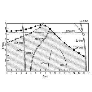
[0096] Figure 3B shows a mapped treatment region of the eye comprising the
cornea, the posterior
capsule, and the limbus. The treatment region can be mapped with computer
modeling, for example
-23-
SUBSTITUTE SHEET (RULE 26)
CA 02938866 2016-08-04
WO 2015/119892 PCMJS2015/014112
ray tracing and phased based optical modeling to incorporate factors such as
laser beam quality,
pulse width, system transmission, numerical aperture, polarization, aberration
correction, and
alignment. The treatment volume is shown extending along the Z-axis from the
posterior surface of
the optically transmissive structure of the patient interface a distance of
over 15 mm, such that the
treatment volume includes the cornea, and the lens in which the treatment
volume of the lens
includes the anterior capsule, the posterior capsule, the nucleus and the
cortex. The treatment
volume extends laterally from the center of the cornea to beyond the limbus.
The lateral dimensions
of the volume are defined by a Y contour anterior to the limbos and by an X
contour posterior to the
limbos. The treatment volume shown can be determined by a person of ordinary
skill in the art
based on the teachings described herein. The lateral positions of predicted
optical breakdown for ZL
fixed to 30 mm and ZL fixed to 20 mm are shown, These surfaces that extend
transverse to the axis
99 along the Z-dimension correspond to locations of optical scanning of the X
and Y galvos to
provide optical breakdown at lateral locations away from the axis 99. The
curved non-planner shape
of the scan path of optical breakdown for ZL- 30 mm and ZL-20 mm can be
corrected with the
mapping and look up tables as described herein. The curved shape of the focus
can be referred to as
a warping of the optical breakdown depth and the look up tables can be warped
oppositely or
otherwise adjusted so as to compensate for the warping of the treatment depth,
for example.
Additionally, the warping inherent in the prediction from the model can be
incorporated in the
generic look-up table and any further error from this predicted form as
indicated by measurement
and application of a correction factor to offset this error may also be called
a warping of the look up
table.
[0097] The treatment region is shown for setting the laser beam energy about
four times the
threshold amount for optical breakdown empirically determined for a beam near
the limbus of the
system. The increased energy or margin above ensures that the beam system will
be able to treat
given variability in contributing factors. Theses contributing factors may
include degradation over
lifetime of the laser with regard to energy, beam quality, transmission of the
system, and alignment.
[0098] The placement of the posterior surface of the optically transmissive
structure of the patient
interface away from the surface of the cornea can provide the extended
treatment range as shown,
and in many embodiments the optically transmissive structure comprises the
lens. In alternative
embodiments, the posterior surface of the optically transmissive structure can
be placed on the
cornea, for example, and the mapping and look up tables as described herein
can be used to provide
the patient treatment with improved accuracy.
-24-
SUBSTITUTE SHEET (RULE 26)
CA 02938866 2016-08-04
WO 2015/119892 PCMJS2015/014112
[0099] The optically transmissive structure of the patient interface may
comprise one or more of
many known optically transmissive materials used to manufactures lenses,
plates and wedges, for
example one or more of glass, BK-7, plastic, acrylic, silica or fused silica
for example.
[001001 The computer mapping of the treatment volume may optionally be
adjusted with mapping
based on measurements of a constructed system as described herein.
[00101] Figure 4A shows correspondence among movable and sensor components of
the laser
delivery system 2. The movable components may comprise one or more components
of the laser
delivery system 2 as described herein. The movable components of the laser
delivery system may
comprise the zoom lens capable of moving distance ZL, the X galvo mirror 96
capable of moving an
angular amount Xm, and the Y galvo mirror 88 capable of moving an angular
amount Ym. The
movable components of the OCT system may comprise the movable OCT reference
arm configured
to move the reference path 106 a distance ZED. The sensor components of the
laser system may
comprise the video camera having X and Y pixels, Pix X and Pix Y,
respectively, and sensor
components of the OCT system such as the spectral domain detection as
described herein. The
patient support which may comprise a bed is movable in three dimensions so as
to align the eye 43
of the patient P with laser system 2 and axis 99 of the system. The patient
interface assembly
comprises an optically transmissive structure which may comprise an interface
lens 96, for example,
configured to be aligned with system 2 and an axis of eye 43. The patient
interface lens can be
placed on the patient eye 43 for surgery, and the optically transmissive
structure can be placed at a
distance 162 from the objective lens 94. In many embodiments, the optically
transmissive structure
comprises lens 96 placed a contact lens optical distance 162 (hereinafter
"CLopt"). The optically
transmissive structure comprises a thickness 164, and the thickness 164 may
comprise a thickness of
the contact lens 96, for example. Although the optically transmissive
structure comprising contact
lens 96 may contact the eye 2, in many embodiments the contact lens 168 is
separated from the
cornea with gap 168 extending between the lens and the vertex of the cornea,
such that the posterior
surface of the contact lens 168 contacts a solution comprising saline or a
viscoelastic solution, for
example.
[00102] Figure 4B shows mapping of coordinate references from an eye space
coordinate reference
system 150 to a machine coordinate reference system 151 so as to coordinate
the machine
components with the physical locations of the eye. The laser system 2 can map
physical coordinates
of the eye 43 to machine coordinates of the components as described herein.
The eye space
coordinate reference system 150 comprises a first X dimension 152, for example
an X axis, a second
Y dimension 154, for example a Y axis, and a third Z dimension 156, for
example a Z axis, and the
-25-
SUBSTITUTE SHEET (RULE 26)
CA 02938866 2016-08-04
WO 2015/119892 PCMJS2015/014112
coordinate reference system of the eye may comprise one or more of many known
coordinate
systems such as polar, cylindrical or Cartesian, for example. In many
embodiments the reference
system 150 comprises a right handed triple with the X axis oriented in a nasal
temporal direction on
the patient, the Y axis oriented superiorly on the patient and the Z axis
oriented posteriorly on the
patient. In many embodiments, the corresponding machine coordinate reference
system 151
comprises a first X' dimension 153, a second Y' dimension 155, and a third Z'
dimension 157
generally corresponding to machine actuators, and the coordinate reference
system of the machine
may comprise one or more of many known coordinate systems such as polar,
cylindrical or
Cartesian, and combinations thereof, for example.
[00103] The machine coordinate reference 151 may correspond to locations of
one or more
components of system 2. The machine coordinate reference system 151 may
comprise a plurality of
machine coordinate reference systems. The plurality of machine coordinate
reference systems may
comprise a coordinate reference system for each subsystem, for example. For
example,
dimension 157 may correspond to movement of the z-telescope lens capable of
moving distance ZL.
The dimension 153 may correspond to movement of the X galvo mirror 86 capable
of moving an
angular amount Xm, and the dimension 153 may correspond to movement of the Y
galvo mirror 88
capable of moving an angular amount Ym. Alternatively or in combination, the
dimension 157 may
correspond to movable OCT reference arm configured to move the reference path
106 a distance
ZED, along with dimension 157 corresponding to a movement of the z-telescope
for the OCT beam,
and the dimension 153 and the dimension 155 may correspond to movement of the
X galvo
mirror 86 and the Y galvo mirror 88, respectively, for the OCT beam. The
dimension 151 may
correspond to X pixels of the video camera and dimension 153 may correspond to
Y pixels of the
video camera. The axes of the machine coordinate reference system may be
combined in one or
more of many ways, for example the OCT reference arm movement of the reference
path 106 the
distance ZED can be combined with movement of the z-telescope lens capable of
moving the
distance ZL, for example. In many embodiments, the locations of the components
of the laser
system 2 are combined when in order to map the plurality of machine coordinate
reference systems
to the coordinate reference system 150 of eye 43.
[00104] In many embodiments, the eye coordinate reference system is mapped
from an optical path
length coordinate system to physical coordinates of the eye based on the index
of refraction of the
tissues of the eye. An example is the OCT ranging system where measurements
are based on optical
thicknesses. The physical distance can be obtained by dividing the optical
path length by the index
of refraction of the material through which the light beam passes. Preferable
the group refractive
-26-
SUBSTITUTE SHEET (RULE 26)
CA 02938866 2016-08-04
WO 2015/119892 PCMJS2015/014112
index is used and takes into account the group velocity of the light with a
center wavelength and
bandwidth and dispersion characteristics of the beam train. When the beam has
passed through more
than one material, the physical distance can be determined based on the
optical path length through
each material, for example. The tissue structures of the eye and corresponding
index of refraction
can be identified and the physical locations of the tissue structures along
the optical path determined
based on the optical path length and the indices of refraction. When the
optical path length extends
along more than one tissue, the optical path length for each tissue can be
determined and divided by
the corresponding index of refraction so as to determine the physical distance
through each tissue,
and the distances along the optical path can be combined, for example with
addition, so as to
determine the physical location of a tissue structure along the optical path
length. Additionally,
optical train characteristics may be taken into account. As the OCT beam is
scanned in the X and Y
directions and departure from the telecentric condition occurs due to the
axial location of the galvo
mirrors, a distortion of the optical path length is realized. This is commonly
known as fan error and
can be corrected for either through modeling or measurement.
[00105] As one or more optical components and light sources as described
herein may have
different path lengths, wavelengths, and spectral bandwidths, in many
embodiments the group index
of refraction used depends on the material and the wavelength and spectral
bandwidth of the light
beam. In many embodiments, the index of refraction along the optical path may
change with
material. For example, the saline solution may comprise a first index of
refraction, the cornea may
comprise a second index of refraction, the anterior chamber of the eye may
comprise a third index of
refraction, and the eye may comprise gradient index lens having a plurality of
indices of refraction.
While optical path length through these materials is governed by the group
index of refraction,
refraction or bending of the beam is governed by the phase index of the
material. Both the phase and
group index can be taken into account to accurately determine the X, Y, and Z
location of a
structure. While the index of refraction of tissue such as eye 43 can vary
with wavelength as
described herein, approximate values include: aqueous humor 1,33; cornea 1.38;
vitreous
humor 1.34; and lens 1.36 to 1.41, in which the index of the lens can differ
for the capsule, the
cortex and the nucleus, for example. The phase index of refraction of water
and saline can be about
1.325 for the ultrafast laser at 1030nm and about 1.328 for the OCT system at
830 nm. The group
refractive index of 1.339 differs on the order of 1% for the OCT beam
wavelength and spectral
bandwidth. A person of ordinary skill in the art can determine the indices of
refraction and group
indices of refraction of the tissues of the eye for the wavelengths of the
measurement and treatment
-27-
SUBSTITUTE SHEET (RULE 26)
CA 02938866 2016-08-04
WO 2015/119892 PCMJS2015/014112
systems as described herein. The index of refraction of the other components
of the system can be
readily determined by a person of ordinary skill in the art based on the
teachings described herein.
[00106] Figure 5A shows a cornea of an eye having stromal and endothelial
folds and a treatment
profile. The eye comprises a cornea. The cornea has an anterior side portion
and a posterior side
portion. The cornea comprises an epithelial layer, a Bowman's membrane, a
stroma and an
endothelium. A Bowman's membrane is located on the anterior side of the eye
between the
epithelium and the stroma. Above Bowman's membrane lies the epithelium. The
epithelium when
covered with a tear film corresponds to an anterior surface of the cornea and
comprises refractive
power of the eye. The stroma comprises a majority of the thickness of the
cornea and the stroma
extends from Bowman's membrane to Descemet's membrane. Descemet's membrane is
located
between the endothelium and the stroma.
[0107] The eye is shown in relation to eye coordinate reference frame 150
having x, y and z axes as
described herein. The eye may comprise an irregular posterior surface
comprising the endothelium.
The endothelium, stroma and Descemet's membrane may comprise folds and the
folds may be
visible through slit lamps in accordance with some embodiments.
[0108] In many embodiments, the eye comprises a degraded optical tissue
surface. The degraded
optical tissue surface may comprise folds of the posterior stromal portion or
irregularities of the
epithelium and combinations thereof. For example, the anterior surface of the
cornea may comprise
an irregularity such as an irregular epithelium and epithelial irregularities.
The epithelial
irregularities may comprise one or more irregularities that affect light
transmission and may scatter
light. On the posterior side of the cornea the stroma may comprise folds and
the folds can affect
light refraction and transmission and in some embodiments can provide light
scatter so as to degrade
vision.
[0109] Work in relation to embodiments suggests that the irregular posterior
surface of the cornea
can be related to folds in the stroma and that by providing a target profile
corresponding to the
irregular folds, the endothelium and Descemet's membrane can be removed more
uniformly. In
many embodiments a portion of the stroma is removed in a manner that decreases
transection of the
collagen fibers of the stroma. The lamellae of the cornea comprise collagen
fibers that extend along
the stroma. The incision profile can extend along the lamella to inhibit
resection of the collagen
fibers,
[0110] In many embodiments, a tissue surface can be defined based on one or
more of the stromal
lamella, the endothelium, or Descemet's membrane, for example. The tissue
surface may extend
along the lamella, for example between the lamella, and the incising treatment
profile can be
-28-
SUBSTITUTE SHEET (RULE 26)
CA 02938866 2016-08-04
WO 2015/119892 PCMJS2015/014112
configured so as to extend along the tissue surface. As light scattering of
the lamella can vary with
the angle of the lamella and collagen fibers, the folds of the lamella and the
tissue surface of the
lamella can be profiled with the measurement system having sufficient
resolution capable of
detecting the stromal folds as described herein.
[0111] The eye can be profiled in one or more of many ways as described
herein. With reference to
coordinate frame 150, the coordinate frame can be used to determine the target
depth of the
treatment profile. The treatment profile can be determined with respect to a
reference frame such as
a reference plane as described herein and the reference plane can be
referenced with respect to an
optical surface of the laser delivery system such as the posterior-most
portion of the patient interface
transmission structure such as the lens as described herein. The eye can be
profiled so as to
determine a posterior surface depth with respect to the reference plane. The
posterior surface depth
can be measured along the x and y axes so as to describe a three-dimensional
depth profile. The
three-dimensional posterior surface depth profile can be used to determine the
target depth profile of
the cornea. The target depth profile can be programmed with the patient. The
target depth may also
be programmed by the user with a user-specified input, such as for example, a
particular distance
from the posterior surface. For example, a user may specify a depth a distance
between the posterior
surface and the target profile of 10 microns and the software can be
programmed to determine the
target depth corresponding to the target profile. In many embodiments, the
cornea comprises a
thickness and the thickness varies along the cornea and the cup profile is
configured so as to vary in
relationship to the thickness to provide a more uniform treatment. The target
depth can be
programmed into the laser system as described herein.
[0112] Figure 5B shows a magnified view of an eye as in Figure 5A, including
folds in stromal
lamella and a target profile to decrease incisions across the lamella, of the
posterior portion of the
cornea as described herein. The posterior portion of the cornea comprises the
endothelium,
Descemet's membrane and stromal lamella as described herein. As shown with
reference to Figure
5B, the folds may comprise folds of the endothelium and Descemet's membrane
and the stromal
lamella. The lamella and the stroma may comprise folds similar to the folds of
Descemet's
membrane and the endothelium so that by programming the treatment to have a
target depth
reference to the frame, similar to the profile of the posterior surface of the
cornea, the cutting of
stromal lamella can be decreased substantially. For example, as shown in
Figure 5B, the target
profile varies so as to decrease and inhibit cutting through the stromal
lamella and so provides a
more uniform removal of tissue in accordance with embodiments.
-29-
SUBSTITUTE SHEET (RULE 26)
CA 02938866 2016-08-04
WO 2015/119892 PCMJS2015/014112
[0113] Figure 5C shows a front view of an eye as in Figure 5A, including folds
in Descemet's
membrane and the lamella. The view shows the thickness of the cornea in
accordance with
embodiments. Figure SC shows an example of a three dimensional representation
of the thickness of
the cornea that can be used to determine the treatment profile. The incising
treatment profile
comprises a maximum dimension across, such as a diameter of a circle as shown
in Figure SC.
Although the treatment profile is show to extend in a circular pattern, the
treatment profile may
comprise one or more of many shapes such as oval, rectangular, square, regular
or irregular. Also,
the outer boundary of the profile where lamellae arc resectcd may comprise an
interlocking profile
such as a jig-saw pattern, for example. The folds as shown in Figure SC
correspond to the varying
thickness of the three dimensional depth profile of the thickness of the
cornea. The three
dimensional thickness profile can be used to determine the target profile as
described herein. For
example, the target profile may comprise a three dimensional target profile or
a representation of the
three dimensional profile corresponding to a three dimensional representation
of the thickness of the
cornea so as to provide a cut into the stromal tissue that decreases cutting
across the stromal lamella.
The coordinate reference frame 150 is shown with reference to Figure SC and
can be used to
determine the thickness profile of the cornea and the appropriate depth of the
incision. As described
with reference to Figure SA, the target profile can be based on the posterior
surface of the cornea and
the thickness, for example, 5 microns, 10 microns or 15 microns, can be
programmed by a user so as
to provide removal of the posterior portion of the cornea so as to prepare the
bed for placement of
the graft tissue via donor.
[00114] Figure 5D illustrates a display window of the laser system showing
folds of the posterior
cornea and a target laser pulse profile having folds to accommodate folds of
the posterior surface.
The display window can be combined with one or more other windows of the
display, and can be
combined with components of the user interface as described herein. The
display comprises a user
input to set an aspect of the target incision profile, such as a dimension of
the profile in relation to
the posterior surface of the cornea. The user can input a parameter that is
used to define the target
profile of the laser beam incision based on the posterior surface profile, for
example with an offset to
the posterior surface profile.
[00115] In many embodiments, the target incision profile of the laser beam is
dimensioned in
relation to the measured posterior surface of the cornea such that folds of
the target profile
correspond to folds of the posterior surface. For example, the posterior
surface profile can be one or
more of offset or scaled to provide the target profile such that the target
profile comprises the folds
of the posterior surface that correspond to folds of the underlying stroma in
at least some
-30-
SUBSTITUTE SHEET (RULE 26)
CA 02938866 2016-08-04
WO 2015/119892 PCMJS2015/014112
embodiments. In many embodiments, the offset of the posterior surface profile
corresponds to a
thickness of the flap removed from the posterior portion of the cornea. The
posterior surface profile
may comprise a representation of a three dimensional surface profile of the
posterior surface of the
cornea, for example.
[00116] In many embodiments, the folds of the stroma can be
measured
directly with a high resolution tomography system configured to provide
sufficiently high resolution
in three dimensions and software configured to identify the folds of stromal
tissue from the images
of the stromal tissue. For example, the tomography system may comprise an
optical coherence
tomography system, or a confocal tomography system, or combinations thereof,
configured to
provide high resolution three dimensional tomography of the cornea. Along a
continuous depth
image, the folds may be observed as variations of intensity of the image.
[0117] Figure 6 shows a cornea as in Figure 5A with Descemet's membrane, the
endothelium, and a
portion of the stroma removed along the treatment profile. The diseased
endothelium and
Descemet's membrane can be removed once the target probe the profile has been
used to treat the
cornea with the plurality of pulses as described herein such that the diseased
tissues can be resected.
As shown in Figure 6 the stoma' bed is exposed on the posterior side of the
cornea. The stromal
bed can be accessed through an incision in the cornea, for example, as can be
performed with the
NEK. In many embodiments, the stromal incision is performed with the laser
system in the manner
similar to as may be done with cataract surgery, the laser system can be used
to cut the cornea at the
periphery of the cornea to provide access to the stromal bed. The target
profile is shown to provide
the shape of the stromal bed with reference to Figure 6.
[0118] Figure 7A shows a donor cornea and a donor treatment profile to remove
a graft for
explantation. The donor cornea comprises structures similar to the cornea
being treated of the
recipient. The donor cornea comprises an anterior surface and a posterior
surface. An epithelium
generally defines the anterior surface of the cornea. A Bowman's membrane is
located between the
stroma and epithelium of the donor cornea. A target profile is shown in the
donor cornea and the
target profile can be defined similarly to the target profile of the treated
eye receiving the donor
graft. For example, the target profile thickness of the donor cornea may
describe a thickness similar
to the thickness of the eye being treated and the target profile can be
defined with respect to the
posterior surface of the donor cornea so as to provide a three dimensional
target profile defined
based on a three dimensional representation of the posterior surface; for
example so as to provide a
thickness of about 10 microns. In many embodiments the donor cornea may
comprise a slightly
-31-
SUBSTITUTE SHEET (RULE 26)
CA 02938866 2016-08-04
WO 2015/119892 PCMJS2015/014112
swollen cornea such that the target profile may correspond to irregularities
of the posterior surface of
the cornea so as to inhibit cutting and transection of the lamella of the
donor cornea stroma.
[0119] Figure 7B shows an initial profile of the graft donor tissue prior to
removal from the eye as in
Figure 7A. The graft tissue comprises Deseemet's membrane and an endothelium
and a portion of
the stroma, each from the donor cornea. As shown in Figure 5B, the graft
comprises an initial
configuration corresponding to the configuration of the graft within the
cornea of the eye. The graft
shown in Figure 7B may comprise a slightly compressed configuration within the
donor cornea due
to swelling of the corneal tissue. It may be related to the state of the donor
cornea when the graft is
harvested.
[0120] Figure 7C shows the graft tissue as in Figures 7A and 7B in an expanded
configuration
subsequent to removal from the eye. The graft may comprise a smooth surface or
a smoother
surface than is shown in Figure 7B when the tissue has been resected from the
donor cornea. The
smoother surface can be provided as the transection of the stromal lamella had
been decreased.
[0121] Figure 8 shows the graft as in Figures 7A to 7C placed in the recipient
cornea subsequent to
healing of the eye. The recipient cornea is shown in a healed configuration
subsequent to placement
of the graft tissue comprising Descemet's membrane, the donor Deseemet's
membrane, the donor
endothelium and the donor stroma. As the endothelium in the healed eye can be
healthy, the
thickness and pumping of the corneal stroma has been restored, such that the
stroma comprises a
smoother surface anteriorly and posteriorly due to the improved health of the
endothelium. The graft
may comprise a smooth surface and is capable of smoothing so as to correspond
to the shape of the
bed of the cornea having the decreased thickness.
[0122] The structures of the recipient cornea as shown in Figure 8 are similar
to the structures of the
recipient cornea shown above and comprise an epithelium, Bowman's membrane
stroma,
endothelium and Descemet's membrane, for example, and the graft, and the
profile of the graft, are
shown with reference to the healed cornea and the donor graft is shown on the
posterior surface of
the cornea.
[00123] Figures 9A to 9D show forming a pocket with a fluid in order to
separate a posterior
corneal flap from the cornea along lamella of the cornea. The fluid can be
used to form the pocket in
combination with embodiments as described herein.
[00124] Figure 9A shows an access incision can be formed in the cornea to
provide access to the
anterior chamber of the eye. A tunneling incision can be formed in a posterior
surface of the cornea
to allow a needle to penetrate the posterior cornea to a predetermined depth
based on the depth of the
tunneling incision. The tunneling incision and the access incision can be
formed with image guided
-32-
SUBSTITUTE SHEET (RULE 26)
CA 02938866 2016-08-04
WO 2015/119892 PCMJS2015/014112
laser beam pulses as described herein, The tunneling incision can be formed in
response to one or
more of the posterior surface profile and the anterior surface profile so that
the tunneling incision
extends a predetermined depth from the posterior surface of the cornea to a
target depth at which the
cornea lamella are to be separated in order to provide the flap of removed
tissue.
[00125] Figure 9B shows a needle inserted through the access incision and into
the tunneling
incision. The tunneling incision can be sized to fit the needle in order to
inhibit passage of air
between the incision and the needle, Although a needle is shown, the structure
introduced into the
eye to provide the fluid that forms the pocket may comprise one or more of
many elongate structures
having an inner channel to provide fluid such as a tube, a hypo tube, a
cannula or a micro-catheter,
for example.
[00126] While the tunneling incision can be shaped and oriented in one or more
of many ways, in
many embodiments the tunneling incision comprises an elongate axis oriented
toward the access
incision of the cornea, which allows the needle to be advanced along the
tunneling incision when the
needle extends through the access incision. In many embodiments the elongate
axis of the tunneling
incision is aligned with an elongate axis of the needle when the needle has
been advanced to the end
of the tunneling incision.
[00127] Figure 9C shows a pocket foi filed with introduction of a fluid
into the cornea through the
tip of the needle positioned along the tunneling incision. The introduction of
fluid separates the
cornea along the lamella in order to separate a flap comprising Descemet's
membrane from the
cornea. A sufficient amount of fluid can be introduced in order to separate
the flap from the cornea
and provide a volume to the pocket such that the flap is separated from the
cornea. The fluid
introduced into the pocket may comprise one or more of many fluids such as a
liquid, a gel, a
viscoelastic, a gas, or air, for example.
[00128] Figure 9D shows one or more peripheral incisions near an outer
boundary of the flap to
provide a smooth outer boundary of the flap. The peripheral incisions can be
made before the flap is
separated from the cornea or after the flap is separated from the cornea, for
example. The peripheral
incision may comprise a circular incision that defines an outer circumference
of the flap. The
peripheral incision may comprise one or more of many shapes such as non-
circular shapes, for
example.
[00129] Figure 10 shows a method 900 of treating a patient, in accordance with
embodiments.
[00130] At a step 910, vision of the eye is measured.
[00131] At a step 920, the posterior surface profile of the cornea is
measured.
[00132] At a step 925, the anterior surface profile of the cornea is measure.
-33-
SUBSTITUTE SHEET (RULE 26)
CA 02938866 2016-08-04
WO 2015/119892 PCMJS2015/014112
1001331 At a step 930, folds are identified of the posterior surface of the
cornea. The posterior
surface may comprise folds of the endothelium, Descemet's membrane, or stroma,
as described
herein, for example. Alternatively or in combination, the folds can be folds
of the posterior stroma,
such as posterior stromal folds.
[00134] At a step 940, an incision profile is determined based on one or more
of the identified folds
or the posterior surface profile of the cornea,
[00135] At a step 945, an access profile is determined through which a
peripheral portion of the
cornea is accessed.
[00136] At a step 947, a tunneling incision profile is determined as described
herein.
[00137] At a step 950, the laser beam is pulsed along the incision profile.
[00138] At a step 955, the laser beam is pulsed along the access profile to
provide access to the
anterior chamber of the eye.
[00139] At a step, 957, the laser beam is pulsed along the tunneling incision
profile to form the
tunneling incision.
[00140] At a step 960, a surgical instrument is advanced through the access
profile. At a step 965,
the donor cornea is measured and incised in a manner similar to the treated
cornea, as described
above.
[00141] At a step 963, fluid is provided to form a pocket and separate the
flap from the recipient
cornea.
[00142] At a step 965, a flap of cornea tissue comprising the endothelium,
Descemet's membrane
and posterior stroma is removed from the recipient cornea.
[00143] At a step 970, the donor cornea is measured and incised in a manner
similar to the treated
cornea as described herein.
[00144] At a step 975, graft tissue is removed from the donor cornea through a
graft incision.
[00145] At a step 980, the graft is advanced to the access channel of the
recipient cornea and the
graft can be folded, shaped or rolled in one or more of many ways to provide a
decreased incision to
the recipient cornea.
[00146] At a step 985, the graft is placed onto a stromal bed of the recipient
cornea.
[00147] At a step 990, the cornea is allowed to heal to decrease swelling and
folds.
[00148] At a step 995, vision of the patient is measured and improves.
[00149] Figure 10 shows a method of treating an eye in accordance with some
embodiments, and a
person of ordinary skill in the art will recognize many adaptations and
variations based on the
-34-
SUBSTITUTE SHEET (RULE 26)
CA 02938866 2016-08-04
WO 2015/119892 PCMJS2015/014112
teachings provided herein. For example, the steps can be performed in a
different order, and the
steps can be removed or repeated. Also, the steps may comprise sub-steps.
[00150] The tangible medium of the processor as described herein can embody
instructions to
perform one or more steps of the method, for example instructions of a
computer program to
perform one or more steps of the method.
[00151] While preferred embodiments of this disclosure have been shown and
described in an
exemplary form with a certain degree of particularity, those skilled in the
art will understand that the
embodiments are provided by way of example only, and that various
modifications, alternative
constructions, changes, substitutions, and variations can be made in the
embodiments without
departing from the spirit or scope of the invention. Thus, it is intended that
this invention cover all
modifications, alternative constructions, changes, substitutions, variations,
as well as the
combinations and arrangements of parts, structures, and steps that come within
the spirit and scope
of the invention as generally expressed by the following claims and their
equivalents.
-35-
SUBSTITUTE SHEET (RULE 26)