Note: Descriptions are shown in the official language in which they were submitted.
CA 02938988 2016-08-16
FOLDING DOOR THRUST REVERSERS FOR AIRCRAFT ENGINES
FIELD OF THE DISCLOSURE
This disclosure relates generally to aircraft engines and, more particularly,
to folding
door thrust reversers for aircraft engines.
BACKGROUND
Aircraft turbofan engines often employ thrust reversal systems to produce a
reverse
thrust to help decelerate the aircraft upon landing (e.g., after touchdown) or
a rejected takeoff,
thereby reducing brake wear and enabling shorter landing distances. For
example, thrust
reversal systems may be deployed upon landing to provide additional stopping
forces in
adverse weather conditions (e.g., on wet, slushy or slippery runways). To
produce reverse
thrust and/or reduce forward thrust, some known thrust reversal systems of
turbofan engines
include a translating cowl and cascade system to redirect or spoil airflow in
a fan duct (e.g.,
provided by a fan of the turbofan engine) that would otherwise produce a
forward thrust.
Other known thrust reversal systems utilize relatively large doors in the
nacelle that pivot
about centers of the respective doors to block the airflow in the fan duct.
SUMMARY
An example apparatus disclosed herein includes a nacelle of a turbofan engine.
A fan
duct is defined between the nacelle and a core of the turbofan engine. The
example apparatus
includes an opening in the nacelle between an outside of the nacelle and the
fan duct. The
example apparatus also includes an inner door and an outer door disposed
within the opening
and pivotably coupled to the nacelle along aft edges of the inner door and the
outer door. The
inner door and the outer door of the disclosed example apparatus arc pivotable
between (1) a
- 1 -
first position in which the inner door and the outer door are disposed within
the opening and
oriented substantially parallel to each other, and (2) a second position in
which the inner door
is disposed in the fan duct and oriented substantially perpendicular to an
outer surface of the
core and the outer door extends outward from the nacelle.
Disclosed herein is an example thrust reverser apparatus for use with a
turbofan
= engine. The example apparatus includes an outer door and an inner door
pivotably coupled to
the outer door via a hinge. In the example apparatus, the inner door and the
outer door are to
be pivotably coupled to an opening in a nacelle of the turbofan engine such
that the inner
door is rotatable into a passageway formed between the nacelle and a core cowl
of the
turbofamengine. The inner door of the example apparatus includes a frame and a
first vane
rotatably coupled the frame.
Disclosed herein is an example thrust reverser apparatus for use with a
turbofan
engine that includes a first outer door coupled to a second outer door and a
first inner door
coupled to a second inner door. The first inner door is coupled to the first
outer door. In the
example apparatus, the first inner door and the first outer door are to be
coupled to an
opening in a nacelle of the turbofan engine. The first and second inner doors
are movable
between (1) a folded position in which the second inner door is parallel to
the first inner door,
and (2) an extended position in which the first and second inner doors extend
into a fan duct
defined between the nacelle and a core cowl of the turbofan engine.
Dsclosed herein is an example apparatus comprising: a nacelle of a,turbofan
engine,
wherein a fan duct is defined between the nacelle and a core of the turbofan
engine; an
opening in the nacelle between an outside of the nacelle and the fan duct; an
inner door and
an outer door disposed within the opening and pivotably coupled to the nacelle
along aft
edges of the inner door and the outer door, the inner door and the outer door
pivotable
.. between a first position in which the inner door and the outer door are
disposed within the
- 2 -
CA 2938988 2020-02-19
opening and oriented substantially parallel to each other, and a second
position in which the
inner door is disposed in the fan duct and oriented substantially
perpendicular to an outer
surface of the core and the outer door extends outward from the nacelle; and a
hatch along an
inner surface of the nacelle adjacent the opening, the hatch movable between a
closed
position and an open position to allow. airflow from the fan duct into a
cavity formed between
the inner door and the outer door when the inner door and the outer door are
in the first
position.
Disclosed herein is an example thrust reverser apparatus for use with a
turbofan
engine, the thrust reverser apparatus comprising: an outer door; and an inner
door pivotably
coupled to the outer door via a hinge, the inner door and the outer door to be
pivotably
coupled to an opening in a nacelle of the turbofan engine such that the inner
door is rotatable
into a passageway formed between the nacelle and a core cowl of the turbofan
engine to
direct airflow in the passageway, the inner door including a frame and a first
vane rotatably
coupled to the frame, the first vane being oriented in the frame such that,
when the inner door
is disposed in the passageway, a rotational axis of the first vane extends
from the nacelle to
the core cowl.
Disclosed herein is an example thrust reverser apparatus for use with a
turbofan
engine, the thrust reverser apparatus comprising: a first outer door pivotably
coupled to a
second outer door adjacent a distal end of the first outer door; and a first
inner door pivotably
coupled to a second inner door adjacent a distal end of the first inner door,
the first inner door
pivotably coupled to the first outer door via a hinge, the first inner door
and the first outer
= door to be pivotably coupled to an opening in a nacelle of the turbofan
engine, the first and
second inner doors movable between a folded position in which the second inner
door is
parallel to the first inner door, and an extended position in which the first
and second inner
- 2a -
CA 2938988 2020-02-19
=
doors extend into a passageway defined between the nacelle and a core cowl of
the turbofan
engine.
Disclosed herein is an example turbofan engine comprising: a nacelle; a core
cowl;
and a thrust reverser, the thrust reverser including: an outer door; an inner
door pivotably
coupled to the outer door via a hinge, the inner door and the outer door to be
pivotably
coupled to an opening in the nacelle such that the inner door is rotatable
into a passageway
formed between the nacelle and the core cowl to direct airflow in the
passageway, the inner
door including a frame and a vane rotatably coupled to the frame, the vane
oriented in the
frame such that, when the inner door is. disposed in the passageway, a
rotational axis of the
vane extends from the nacelle to the core cowl; and an actuator coupled
between the nacelle
and at least one of the outer door and the inner door.
BRIEF DESCRIPTION OF THE DRAWINGS
FIG. 1 depicts an example aircraft having an example turbofan engine capable
of
employing an example thrust reverser constructed in accordance with the
teachings disclosed
herein.
-2b -
CA 2938988 2020-02-19
CA 02938988 2016-08-16
FIG. 2A is a partial cross-sectional view of the example turbofan engine of
FIG. 1
showing an example thrust reverser, having an example inner door and an
example outer
door, in a retracted or non-deployed position.
FIG. 2B is a partial cross-sectional view of the example turbofan engine of
FIG. 1
-- showing the example thrust reverser of FIG. 2A in a partially deployed
position.
FIG. 2C is a partial cross-sectional view of the example turbofan engine of
FIG. 1
showing the example thrust reverser of FIG. 2A in a deployed position.
FIG. 3 illustrates example linear actuators capable of deploying and/or
retracting the
example inner and outer doors of the example thrust reverser of FIG. 2A.
FIG. 4 illustrates an example rotary actuator capable of deploying and/or
retracting
the example inner and outer doors of the example thrust reverser of FIG. 2A.
FIG. 5 illustrates the example inner door of the example thrust reverser of
FIG. 2A
having rotatable vanes.
FIG. 6 is a cross-sectional view of one of the rotatable vanes of FIG. 5
showing an
example axis of rotation.
FIG. 7A is a cross-sectional view of the example rotatable vanes of FIG. 5 in
a closed
position.
FIG. 7B is a cross-sectional view of the example rotatable vanes of FIG. 5 in
an open
position.
FIGS. 8A-8E illustrate an example sequence of deploying the example thrust
reverser
of FIG. 2A using an example hatch to pressurize an area between the example
inner and outer
doors.
FIG. 9 illustrates the example thrust reverser of FIG. 2A in which the example
inner
and outer doors include respective hinged extensions.
- 3 -
CA 02938988 2016-08-16
Certain examples are shown in the above-identified figures and described in
detail
below. In describing these examples, like or identical reference numbers are
used to identify
the same or similar elements. The figures are not necessarily to scale and
certain features and
certain views of the figures may be shown exaggerated in scale or in schematic
for clarity
and/or conciseness. Additionally, several examples have been described
throughout this
specification. Any features from any example may be included with, a
replacement for, or
otherwise combined with other features from other examples.
DETAILED DESCRIPTION
Disclosed herein are example thrust reversers for use with aircraft engines,
such as
turbofan engines. The example thrust reversers disclosed herein utilize less
space than
known thrust reversers and require less actuating force to deploy and/or
retract. As such, the
example thrust reversers are generally lighter, smaller and more easily
integrated into the
airframe structure of a turbofan engine. Further, the example thrust reversers
disclosed
.. herein are structurally compatible with turbofan engines having relatively
high bypass ratios
(such as those implementing variable area nozzles) and produce efficient
reverse thrust to
decelerate an aircraft. However, before turning to the detailed aspects of the
disclosed
example thrust reversers, a brief discussion of high bypass ratio turbofan
engines and known
thrust reverser systems is provided below.
A turbofan engine, sometimes referred to as a fanjet, is a common type of air-
breathing jet engine used in aircraft propulsion. A turbofan engine includes
an engine core
(e.g., gas turbine engine) and a fan, powered by the engine core, which
produce thrust by
accelerating air rearwards. In contrast to a turbojet engine, in a turbofan
engine some of the
air bypasses the engine core through a fan duct or bypass formed between a
nacelle and the
.. engine core. As used herein, bypass ratio (BPR) refers to the ratio between
the mass flow
- 4 -
CA 02938988 2016-08-16
rate of air through the fan duct that bypasses the engine core and the mass
flow rate of air
passing through the engine core. In general, turbofan engines are relatively
fuel efficient and
have reduced noise compared to other types of aircraft engines. Recent trends
in improving
thrust specific fuel consumption for subsonic transports has lead to
increasing BPRs of
turbofan engines. Ultra High Bypass Ratio (UHBPR) engines, for example, have
BRPs of 12
and above and provide improved in thrust specific fuel consumption.
However, airframe integration issues become limiting factors in reducing
flight fuel
consumption of high BPR turbofan engines. In particular, the limitation for
continuing to
increase the BPR becomes the increasing nacelle drag and/or the weight for
very large
diameter fans. In other words, improving propulsion efficiency and reducing
noise by
increasing the BPR in turbofan engines results in increasing the fan diameter
for a given
thrust. Increasing the fan diameter requires a relatively larger nacelle,
which results in
increased surface area. As such, to increase the BPR, relatively larger fans
are required and,
thus, greater weight and drag is produced by the nacelle of the engine.
Additionally, the propulsive efficiency improvement with BPRs above 12 results
from
the fan pressure ratio dropping below 1.4. With the lower fan pressure ratio,
the fan nozzle
exit area needs to be increased during take-off to achieve the optimum match
for minimum
specific fuel consumption (SFC) during cruise. Otherwise, there is excessive
back pressure
during take-off, resulting in little or no fan stall margin. Therefore, high
BPR turbofan
engines employ variable area nozzles (VANs) to increase performance and
further reduce
flyover noise. In particular, VANs can be opened to increase the BPR to reduce
noise at the
FAA FAR 36 (Federal Aviation Administration Federal Aviation Regulations)
cutback and
approach noise measuring points. VANs are thus a valuable feature contributing
to
improving performance and reducing noise in UHBPR turbofan engines.
- 5 -
CA 02938988 2016-08-16
Known thrust reversers use clamshell or target doors, pivoting doors, or
translating
cowls with internal blocker doors and cascade turning vanes. While early
turbofan engines
reversed both fan and core flows, with higher BPR engines, reversing only the
fan airflow has
been determined to be acceptable by the aircraft community to provide
sufficient deceleration
(e.g., on slippery runways). The clamshell and target door type thrust
reversers are typically
used on turbojet engines and low to medium BPR turbofan engines. However, the
weight
penalty for clamshells and target doors becomes excessive for higher BPR
turbofan engines.
For turbofan engines with BPRs of up to about 5 or 6, translating cowl or
pivot door
reversers are used. Pivoting door reversers utilize pivoting doors are
disposed around the
.. nacelle of the turbofan engine. The pivoting doors pivot about their center
axes. When
deployed, the doors pivot such that the lower half of the door is disposed in
the fan duct while
the upper half of the door is disposed outside of the nacelle. The lower half
of the door is
positioned aft of the pivot point to block the internal flow and the flow
reversal is done
outside of the nacelle by the upper half of the door. However, with turbofan
engines having
BPRs above about 6, such as UHBPR engines, the pivot door size becomes
excessive because
of the large fan duct height or width (i.e., the distance between the outer
surface of the engine
core and the inner surface of the nacelle, which define the bypass or fan duct
passageway).
Therefore, translating cowl thrust reversers are typically used for turbofan
engines
with BPRs of 6 and above. Translating cowl thrust reversers employ translating
cowls
having cascade turning vanes. The cascades may translate or be fixed are used
on the highest
BPR engines. However, the cascades require an increased area because of
blockage from
turning vanes and the additional surface area for turning flow within the
vanes. Further,
translating cowl thrust reversers require extra length for the cascade turning
vanes and
present integration challenges with VANs and, thus, UHBPR engines.
- 6 -
CA 02938988 2016-08-16
Disclosed herein are example thrust reversers (e.g., reverse thrust apparatus)
for use
with turbofan engines. The example thrust reversers utilize folding doors,
which include an
outer door and an inner door, that are hingeably coupled to an opening in a
nacelle of a
turbofan engine. In general, the example thrust reversers operate between a
first or retracted
position (e.g., a non-deployed position, a closed position, etc.), in which
the inner and outer
doors are folded and stored in the opening in the nacelle, and a second or
deployed position
(e.g., an open position, an extended position, etc.) in which the inner door
is rotated into a fan
duct of the turbofan engine and the outer door is rotated to extend outward or
away from the
nacelle. In the deployed position, the inner door blocks the airflow through
the fan duct,
thereby directing the airflow in the fan duct through the opening in the
nacelle. The outer
door further directs the airflow outward from the nacelle. In some examples,
in the deployed
position, the outer door is angled to direct the airflow in the reverse
direction (i.e., in a
direction opposite of the thrust created by the engine core).
In some examples, in the deployed position, the inner door is rotated to a
position in
which the inner door is perpendicular to the engine core and/or the direction
of the airflow
through the fan duct. As such, the length of the inner door is at or near a
theoretical length
needed to block the airflow in the fan duct (e.g., the shortest distance
between the nacelle and
the engine core). Therefore, the length of the inner door is smaller than the
blocking devices
of other known thrust reversal systems. As a result, the opening in the
nacelle used to store
the inner and outer doors is relatively smaller. Thus, the disclosed example
thrust reversers
minimize added weight and/or drag of the nacelles, especially for subsonic
transports
powered by UHBPR engines. In some examples, to further reduce the space used
by the
example thrust reversers, the inner and outer doors may include hinged
extensions that fold
back onto themselves in the retracted position, further reducing the length
needed in the
nacelle to accommodate the example thrust reversers.
- 7 -
CA 02938988 2016-08-16
=
In some examples, the inner door and/or outer door are deployed and/or
retracted via
one or more actuators. In some examples, to decrease actuating force needed to
retract the
inner door from the deployed position, the inner door includes one or more
shutter vanes that
rotate between a closed position and an open position. In the closed position
the shutter
vane(s) block the airflow through the fan duct, thereby diverting the airflow
through the
opening in the nacelle. When retracting the inner door, the shutter vane(s)
may be rotated to
the open position, such that the airflow in the fan duct can flow through the
inner door. As a
result, the force generated by the airflow against the inner door is less than
with the shutter
vane(s) closed and, thus, less actuating force is needed to retract the inner
door. In some
examples, the shutter vane(s) are biased, via springs, in the closed position.
Additionally or
alternatively, the shutter vane(s) may be locked in the closed position. When
retracting the
inner door, for example, the shutter vane(s) may be unlocked or released. In
such an
example, the airflow acting against the shutter vane(s) causes the vane(s) to
rotate to the open
position (e.g., by overcoming the biasing force from the spring(s)), thereby
allowing the
airflow to pass through the inner door. As a result, smaller (and, thus,
lighter) actuating
device(s) may be utilized to move the inner door between the deployed and
retracted position.
In some examples disclosed herein, the thrust reverser includes a hatch or
door along
an inner surface of the nacelle (e.g., the boundary of the fan duct) that
opens to allow the
airflow into the space between the inner and outer folded doors. The high
pressure airflow in
the fan duct then flows into the space between the inner and outer doors and
acts to open or
deploy the inner and outer doors. As such, minimal actuating force (if any) is
needed to
deploy the example thrust reverser. Therefore, smaller (and, thus, lighter)
actuating device(s)
may be utilized to move the inner door between the retracted and deployed
position. In some
examples, the hatch is biased, via a spring, toward the closed position. In
some examples, the
hatch is also locked via a latch in the closed position. To open the hatch,
the latch is
- 8 -
CA 02938988 2016-08-16
unlocked. The high pressure airflow through the fan duct counters the spring
force and opens
the hatch and, thus, allows the high pressure airflow to pressurize the space
between the inner
and outer doors.
Further, the example thrust reversers disclosed herein are structurally
compatible with
.. VANs employed on UHBPR turbofan engines, for example. In some examples, the
thrust
reversers include a reverser frame that may be integrated with and/or coupled
to the VAN.
The example thrust reversers, which employ folding doors, use relatively less
space and are
generally lighter than known thrust reversers. Thus, the disclosed example
thrust reversers
result in reduced sized of the fan nozzle/thrust reverser, particularly when
the BPR is greater
than 12 and a VAN is employed.
FIG. 1 illustrates an example aircraft 100 including wings 102 (e.g., a right
wing and
a left wing) extending laterally outward from a fuselage 104. Each of the
wings 102 of the
illustrated example supports an aircraft engine 106 via a pylon 108. Each
aircraft engine 106
of the illustrated example is a turbofan engine that may embody aspects of the
teachings of
.. this disclosure. For example, the aircraft engine 106 illustrated in FIG.1
includes a thrust
reverser 110 constructed in accordance with the teachings disclosed herein.
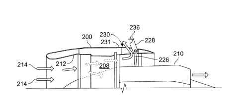
FIG. 2A is a partially cross-sectioned view of one of the example aircraft
engines 106
of FIG. I. As illustrated in FIG. 2A, the aircraft engine 106 (e.g., a
turbofan engine) includes
a nacelle 200 (e.g., a fan nacelle) and an engine core 202 (e.g., a gas
turbine engine)
surrounded by the nacelle 200. Air provided to the engine core 202 is highly
pressurized
(e.g., via one or more compressors) and provided to a combustion chamber of
the engine core
202, where fuel is injected and mixed with the highly pressurized air and
ignited. The engine
core 202 powers a fan 206 disposed axially upstream from the engine core 202.
The fan 206
rotates within a fan cowl 207 (e.g., a fan frame) of the nacelle 200. A fan
duct 208 (e.g., a
bypass, a passageway, a channel, a nozzle duct, etc.) is defined between an
outer wall or core
- 9 -
cowl 210 of the engine core 202 and an inner wall 212 of the nacelle 200. As
the fan 206
rotates, the fan 206 produces airflow 214 (as shown by the arrows) into an
inlet cowl or air
intake 216 of the nacelle 200. A portion of the airflow 214 flows to the
engine core 202 and
a portion of the airflow 214 flows through the fan duct 208 (e.g., aft of the
fan cowl 207).
The thermal energy from the combustion chamber of the engine core 202 is
exhausted (e.g.,
via one or more turbincs) to a nozzle 218. The converted thei __________ mai
energy of the engine core
202 and the accelerated airflow 214 of the fan duct 208 are exhausted from an
all end of the
engine 106 to produce forward thrust that propels the aircraft 100 (e.g., in a
forward
direction). In the illustrated example, the nacelle 200 includes a variable
area nozzle (VAN)
222 (e.g., a fan exit or exhaust nozzle). In some examples, the VAN 222 is
supported by one
or more struts 224 (e.g., structural supports) disposed radially around the
core cowl 210
between the core cowl 210 and the VAN 222.
To reverse the flow path of the' thrust and slow the aircraft 100, the example
engine
106 of FIG. 2A includes the example thrust reverser 110. In the illustrated
example, the
thrust reverser 110 includes an internal or inner door 226 (e.g., a thrust
reversal blocking
door, a first folding door) and an external or outer door 228 (e.g., a
deflector door, a second
folding door) and that are pivotably coupled to the nacelle 200. The inner
door 226 and the
outer door 228 are disposed in a port or opening 230 in a thruster reverser
frame 231 (e.g., a
fixed frame, a reverser frame) that connects an outside of the nacelle 200 and
the fan duct
208. The frame 231 may be may be integral with or coupled to the fan cowl 207.
In the
illustrated example, the VAN 222 is disposed aft (e.g., downstream) of the
opening 230.
Therefore, in the illustrated example, the nacelle 200 includes the air intake
216, the fan cowl
207, the thruster reverser frame 231, and the VAN 222. The example frame 231
may provide
a strong support base for the VAN 222. In some examples, the frame 231 is a
separate
structure (e.g., a ring-shaped or annular shell) coupled between the fan cowl
207 and the
- 10
CA 2938988 2020-02-19
CA 02938988 2016-08-16
VAN 222. In other examples, the frame 231 is integrally formed with the fan
cowl 207
and/or the VAN 222 (e.g., with the strut(s) 224).
In the illustrated example, the inner door 226 and the outer door 228 are
pivotably
coupled to each other and the nacelle 200 via a hinge 232 (e.g., are hingeably
coupled) along
rear or after edges of the respective outer and inner doors 226, 228. In
particular, in the
illustrated example, the inner and outer doors 226, 228 are pivotably coupled
to the nacelle
200 in the opening 230. As disclosed in further detail herein, the inner and
outer doors 226,
228 of the example thrust reverser 110 are movable (e.g., pivotably,
rotatable, etc.) between a
retracted (e.g., folded, stored, non-deployed, etc.) position, as illustrated
in a FIG. 2A, and a
deployed (e.g., unfolded, extended, etc.) position in which the inner door 226
is rotated to
block the airflow 214 in the fan duct 208 and the outer door 220 is rotated
outward to direct
the airflow 214 outward and/or in a reverse direction (e.g., in a direction at
least partially
opposite to that of the thrust generated by the engine core 202). In the
retracted position, as
shown in FIG. 2A, the inner and outer doors 226, 228 are disposed or stored
within the
opening 230 in the nacelle 200 and are oriented substantially parallel to each
other.
FIG. 2B illustrates the example thrust reverser 110 in a partially deployed
position. In
the illustrated example, the inner door 226 is rotated downward (in the
counter-clockwise
direction) (e.g., into the fan duct 208) and the outer door 220 is rotated
upwards (in the
clockwise direction). In some examples, as disclosed in further detail herein,
the inner door
.. 226 and/or the outer door 228 may be rotated via an actuator and/or a
spring. In some
examples, as disclosed in further detail herein, the inner door 226 and/or the
outer door 228
may be deployed with the force of the airflow 214 through the fan duct 208. As
the inner and
outer doors 226, 228 are opened, the force of the airflow 214 against the
inner and outer
doors 226, 228 acts to rotate the inner and outer doors 226, 228 and deploying
the example
thrust reverser 110. A perspective view of the outer door 228 is illustrated
in FIG. 28. As
- 11 -
CA 02938988 2016-08-16
illustrated, the outer door 228 includes a first side wall 233, a second side
wall 234 and an
outer wall 235 that define an opening 237. In the non-deployed position, as
shown in FIG.
2A, the inner door 226 may disposed within the opening 237 of the outer door
228.
FIG. 2C illustrates the example thrust reverser 110 in the fully deployed
position. As
illustrated, the inner door 226 is blocking (e.g., obstructing) the fan duct
208, which directs
the airflow 214 through the fan duct 208 upward or outward through the opening
230 and in a
direction substantially perpendicular to the direction of the fan duct 208.
The airflow 214 is
then directed in the reverse (toward the front) direction via the outer door
228. In the
example deployed position of FIG. 2C, the inner door 226 is substantially
perpendicular to
the core cowl 210 of the engine core 202 and/or the direction of the airflow
214 through the
fan duct 208. As a result, a length the inner door 226 (e.g., from the hinge
to a distal end of
the inner door 226) need only be about the same as a height of the fan duct
208 (e.g., a
distance between the core cowl 210 and the inner wall 212 of the nacelle 200
near the
opening 230). Therefore, the area (e.g., the opening 230) used to accommodate
(e.g., store,
contain, etc.) the example thrust reverser 110 is smaller than an opening used
in many known
translating cowl type thrust reversers. In the illustrated example, the inner
door 226 is rotated
about 90 between the retracted position (e.g., a first position) and the
second or deployed
position (e.g., a second position). However, in other examples, the inner door
226 may be
rotated more or less depending on the relative angle between the nacelle 200
and the core
cowl 210.
In some examples, in the deployed position, the outer door 228 is aligned
(e.g.,
coplanar) with the inner door 226 (e.g., rotated 180 relative to the inner
door 226). For
example, the outer door 228 may be oriented substantially perpendicular to the
nacelle 200 in
the deployed position. In other examples, the outer door 228 may be angled
toward a front of
.. the engine 106 in the deployed position to direct the airflow 214 in the
reverse direction.
- 12 -
CA 02938988 2016-08-16
Additionally or alternatively, in some examples a kicker or fence 236 extends
from a distal
end of the outer door 228 (FIGS. 2B and 2C). The fence 236 is angled with
respect to the
outer door 228 and acts to direct the airflow 214 in the reverse direction. In
some examples,
one or more stops may be employed to prevent the outer door 228 from over-
rotating.
In some examples, the hinge 232 is spring-loaded (e.g., via a torsion spring)
to bias
the inner and outer doors 226, 228 to the deployed position. In such examples,
the inner and
outer doors 226, 228 may be locked (e.g., via an actuator or latch) in the
closed position.
When the inner and outer doors 226, 228 are unlocked, the spring-loaded hinge
232 biases
the inner and outer doors 226, 228 to the deployed position. In some examples,
one or more
actuators may be employed to deploy and/or retract the inner and outer doors
226, 228, as
disclosed in further detail herein. In the illustrated example, the inner and
outer doors 226,
228 are substantially trapezoid shaped. In some examples, the inner and outer
doors 226, 228
may have longer aft edges (e.g., the edges hear the hinge 232) and shorter
fore edges (e.g.,
are in the shape of a trapezoid). In some examples, the inner and outer doors
226, 228 are
curved to match the corresponding profile of the outer shape of the nacelle
200 and the fan
duct 208.
In the deployed position, the outer door 228 of the example thrust reverser
110 also
produces relatively high base drag (e.g., the drag of the nacelle 200)
compared to other
known thrust reversers, such as the translating cowl thrust reverser where no
base drag is
present. Such base drag also aids in decelerating the aircraft 100 more
quickly. Additionally,
as disclosed herein, the example thrust reverser 110 can also be
advantageously used with
UHBPR engines, which produce relatively higher ram drag (e.g., drag generated
by the use of
a relatively large fan intake flow, such as the air intake 216) than smaller
BPR engines. In
general, the deceleration force on the aircraft 100 is the sum of the reverse
thrust (e.g.,
generated by the example reverser thruster 110), braking ground friction,
engine ram drag
- 13-
CA 02938988 2016-08-16
and/or airplane ram drag. In some examples, even a 10% fan reverser efficiency
on a
UHBPR engine with the example thrust reverser 110 provides a deceleration
comparable to
known high BPR thrust reversers that have a higher reverse turning efficiency
of about 45%,
due to of the much higher deceleration forces from the increased ram drag
and/or base drag.
Thus, even with less reverse thrust, the example thrust reverser 110 provides
comparable, if
not better, airplane deceleration capabilities than current high BPR engines
that may have
high reverse thrust but produce less ram drag and less base drag.
While only one folding door set (e.g.. the inner door 226 and the outer door
228) is
illustrated in FIGS. 2A-2C, it is understood that in some examples, the
example thrust
reverser 110 may include a plurality of folding door sets that are disposed
circumferentially
around the nacelle 200 of the engine 106 (as illustrated in FIG. 1). The
folding doors may be
substantially the same as any of the example thrust reversers disclosed
herein. In some
examples, the folding door sets are spaced evenly from each other around the
nacelle 200
(e.g., 12 folding door sets disposed every 30 ). The example folding door sets
may be
controlled (e.g., via one or more controllers and/or actuators) to deploy
and/or retract
substantially simultaneously (e.g., via a thrust reverser control system of
the aircraft 100).
As disclosed herein, in some examples, one or more actuators may be employed
to
move the inner and outer doors 226, 228 of the example thrust reverser 110
from the retracted
position (as shown in FIG. 2A) to the deployed position (as shown in FIG. 2B).
The example
thrust reverser 110 may employ any hydraulic, pneumatic or electric actuator.
For example,
FIG. 3 illustrates an example implementation using linear actuators (e.g.,
push-pull actuators)
to move the inner and outer doors 226, 228. In particular, a first linear
actuator 300 is
coupled between the nacelle 200 and the inner door 226 and a second linear
actuator 302 is
coupled between the nacelle 200 and the outer door 228. The first and second
linear
actuators 300, 302 operate to open or close the inner and outer doors 226,
228.
- 14 -
FIG. 4 illustrates another example implementation using a rotary actuator to
move the
inner and outer doors 226, 228. In the illustrated example, a rotary actuator
400 having a
linear screw 402 is coupled to the nacelle 200. A translating link 404 (e.g.,
a plate) having a
threaded opening is coupled between the inner door 226 and the outer door 228.
As the linear
screw 402 is rotated, the link 404 is translated toward or away from the hinge
232 to move
the inner and outer doors 226, 228. In other examples, other types of
actuators having other
arrangements may be implemented to move the inner and outer doors 226, 228.
Once in the deployed position, significant actuating force may be needed to
close the
inner door 226 against the force of the airflow 214 acting on the inner door
226. In some
examples, to substantially reduce and/or eliminate the force needed to retract
the inner and
outer doors 226, 228, the inner door 226 of the example thrust reverser 110
may include one
or more rotatable vanes (e.g., shutter vanes, panels, panes, etc.). FIG. 5 is
a perspective view
of the example inner door 226. In the illustrated example, the inner door 226
includes a
frame 500 and a first vane 502, a second vane 504 and third vane 506 (e.g.,
shutter vanes,
panes, panels, etc.) rotatably coupled to the frame 500. In the deployed
position, a top end
505 of the frame 500 is disposed near the nacelle 200 and a bottom end 507 of
the frame 500
is disposed at or near the core cowl 210. In some examples, one or more seals
may be
provided on the bottom end 507 the frame 500 to provide sealing engagement
between the
inner door 226 and the core cowl 210. In the illustrated example, a portion of
the hinge 232
is depicted on a top of the frame 500 to illustrate the axis about which the
inner door 226
rotates.
In the illustrated example of FIG. 5, the first, second and third vanes 502,
504, 506 are
rotatable between a closed position (as shown in FIG. 5) and an open position,
in which the
first, second and third vanes 502, 504, 506 are rotated about 90 (e.g., a
quarter turn) to allow
the airflow 214 (FIG. 2C) to pass between the first, second and third vanes
502, 504, 506 and,
- 15 -
CA 2938988 2020-02-19
CA 02938988 2016-08-16
thus, through the inner door 226. In the illustrated example, the first,
second and third vanes
502, 504, 506 are rotatable about respective first, second and third axes 508,
510, 512.
In some examples, the first, second and third vanes 502, 504, 506 are biased,
via
springs, in the closed position. An enlarged view of a top of the first vane
502 is illustrated in
FIG. 5. As shown, the first vane 502 is coupled to the frame 500 via a first
shaft 514 about
which the first vane 502 rotates. In the illustrated example, a torsion spring
516 is coupled
between a first post 518 extending from the frame 500 and a second post 520
extending from
the first vane 502. If the first vane 502 is rotated, the force from the
spring 516 biases the
first vane 502 back to the closed position. In some examples, a latch 522 is
provided to lock
the first vane 502 in the closed position. In the illustrated example, the
latch 522 is disposed
within the frame 500 and includes a locking pin 524 that is movable into a
recess or bore 526
in the first vane 502. The latch 522 may be electrically and/or mechanically
actuated (e.g.,
via a signal from a thrust reverser control system implemented in the aircraft
100).
FIG. 6 illustrates a cross-sectional view of the example first vane 502. As
shown in
the illustrated example, the first vane 502 is rotatable about the first axis
508 between the
closed position and the open position (shown in dashed lines). In the
illustrated example, the
first axis 508 is offset from a center of pressure of the first vane 502. In
other words, when
the airflow 214 (FIG. 2C) is acting against the first vane 502, the center of
pressure created
by the pressure from the airflow 214 is offset (e.g., aft) from the first axis
50g. As a result,
when the latch 522 is opened or unlocked, the force from the airflow 214
rotates the first vane
502 about the first axis 508 into the opened position (as shown in the dashed
lines). The
spring 516 may be sized to allow the airflow 214 to rotate the first vane 502
when the first
vane 502 is unlocked. The second and third vanes 504, 506 (FIG. 5) may also
include springs
and latches, similar to the spring 516 and the latch 522, and operate in the
same way. Thus,
when the inner door 226 is deployed, and when the latches (e.g., the latch
522) are opened or
-16-
CA 02938988 2016-08-16
unlocked, the first, second and third vanes 502, 504, 506 may be rotated to
the open position
by the aerodynamic force of the airflow 214. Once in the open position, the
inner door 226
may be closed or retracted with relatively less actuating force. After the
inner door 226 is
retracted, the springs (e.g., the spring 516) of the first, second and third
vanes 502, 504, 506
may bias the respective vanes 502, 504, 506 back to the closed position (e.g.,
when less
airflow 214 is acting on the first, second and third vanes 502, 504, 506), as
disclosed in
further detail herein.
FIG. 7A illustrates a cross-sectional view of the first, second and third
vanes 502, 504,
506 in the closed position and FIG. 7B illustrates the first, second and third
vanes 502, 504,
506 in the open position. In the closed position, the airflow 214 is
obstructed by the first,
second and third panes 502, 504, 506 and, thus, diverted by the inner door 226
up through the
opening 230 (FIG. 1) in the nacelle 200 (FIG. 1). When retracting the inner
door 226, the
latches (e.g., the latch 522 illustrated in FIG. 5) of the first, second and
third vanes 502, 504,
506 may be opened to release the first, second and third vanes 502, 504, 506.
The pressure
from the airflow 214 forces the first, second and third vanes 502, 504, 506 to
rotate (e.g.,
because of the off center rotational axes) to a position in which the first,
second and third
vanes 502, 504, 506 are substantially parallel to the direction of the airflow
214, as shown in
the opened position in FIG. 7B. As such, the difference between the air
pressure upstream of
the inner door 226 and the air pressure downstream of the inner door 226 is
substantially
reduced, thereby enabling the inner door 226 to be closed with reduced
actuating force.
In some examples, the first, second and third vanes 502, 504, 506 are shaped
to act as
airfoils and/or rotated to a position to produce a lift force in the forward
(e.g., clockwise)
direction (e.g., opposite to that of the airflow 214 through the fan duct
208). Such a fonvard
lift force helps retract the inner door 226 when rotating the inner door 226
against the force of
the airflow 214. For example, the first vane 502, as illustrated in FIG. 7B,
is in a position to
- 17-
CA 02938988 2016-08-16
produce a forward lift (e.g., to the left in FIG. 7B). The curved shape or
profile of the first
vane 502 and the position of the first vane 502 relative to the airflow 214
generate a lift force
in a direction opposite of the airflow 214. In some examples, the position of
the first vane
502 is between about 3 and about 15 relative to the oncoming airflow 214.
In some
examples, the inner door 226 includes a stop to prevent the first vane 502
from over rotating
and, thus, hold the first vane 502 in a position that generates lift In some
examples, stops
may similarly be provided for the second and third vanes 504, 506 to likewise
hold the
second and third vanes 504, 506 in optimal positions relative to the oncoming
airflow 214 to
generate lift force in the opposite direction of the airflow 214.
In the illustrated example, the inner door 226 includes the three example
vanes.
However, in other examples, the inner door 226 may include more or fewer
vanes. Further,
in the illustrated example, the first, second and third vanes 502, 504, 506
are oriented
vertically (e.g., in a direction to span the height of the fan duct 208
between the core cowl
210 and the nacelle 200). In other words, when the inner door 226 is disposed
in the fan duct
208, the first vane 502 is oriented such that a first end 528 (e.g., a top
end, an aft end) of the
first vane 502 is at or near the nacelle 200 and a second end 530 (e.g., a
bottom end, a fore
end) is at or near the core cowl 210. However, in other examples, the first,
second and third
vanes 502, 504, 506 may be oriented horizontally. In some examples, the outer
door 228 may
additionally or alternatively include one or more rotating vanes, which may
operator similar
to the first, second and third vanes 502, 504, 506 of the inner door 226.
FIGS. 8A-8E illustrate an example sequence of deploying the example thrust
reverser
110 where little or no actuating force is used. FIG. 8A illustrates the inner
and outer doors
226, 228 in the fully retracted or non-deployed position. While in the fully
retracted position,
the airflow 214 travels through the fan duct 208 and exits the VAN nozzle 222.
The
relatively high pressure airflow 214 in the fan duct 208 creates a pressure on
a bottom of the
- 18 -
CA 02938988 2016-08-16
inner door 226 that maintains the inner door 226 in the closed position. To
enable the inner
and outer doors 226, 228 to open without any actuation device (or relatively
minimal
actuating force), the example thrust reverser 110 may include a hatch 800
(e.g., a door, a flap,
etc.) along the inner wall 212 of the nacelle 200 adjacent the opening 230. In
the enlarged
.. view shown in FIG. 8A, the inner door 226 has been removed for clarity. As
illustrated in the
enlarged view, the hatch 800 is biased toward a closed position via a spring
802, which is
coupled between the nacelle 200 and the hatch 800. In the illustrated example,
a latch 804 is
employed to lock the hatch 800 in the closed position. The latch 804 may be
electrically
and/or mechanically actuated (e.g., via a signal from a thrust reverser
control system
implemented in the aircraft 100).
As shown in FIG. 8B, the latch 804 may be unlocked or opened to release the
hatch
800. In the enlarged view shown in FIG. 8B, the inner door 226 has been
removed for
clarity. The high pressure airflow 214 in the fan duct 208 counters (e.g.,
overcomes) the
force from the spring 802 and opens the hatch 800 (e.g., rotates the hatch 800
about a hinge
.. or pivot axis). Once opened, the high pressure airflow 214 flows into the
space (e.g., cavity,
area, void, etc.) between the inner and outer doors 226, 228, thereby
stabilizing or reducing
the pressure difference across the two sides of the inner door 226 (e.g., by
pressurizing the
space between the inner and outer doors 226, 228).
In the illustrated example, the airflow 214 flowing into the hatch 800 forces
the inner
door 226 to rotate downwards (counter-clockwise) and the outer door 228 to
rotate upwards
(clockwise), as illustrated in FIGS. 8C and 8D. In some examples, one or more
actuators
(e.g., the actuators 300, 302 of FIG. 3 or the actuator 400 of FIG. 4) may be
used to start the
deployment, and then the high pressure airflow 214 blows the inner and outer
doors 226, 228
open. FIGS. 8C and 8D show the airflow 214 forcing the inner and outer doors
226, 228 to
open or deploy. While deploying, the first, second and third vanes 502, 504,
506 (FIG. 5) of
- 19-
CA 02938988 2016-08-16
the inner door 226 are in the closed position, thereby providing the maximum
surface against
which the airflow 214 can act.
FIG. 8E illustrates the inner and outer doors 226, 228 in the fully open
deployed
position. As illustrated, the inner door 226 substantially blocks all airflow
214 in the fan duct
208. The airflow 214, as illustrated by the arrows, is directed through the
opening 230 in the
nacelle 200. In the illustrated example of FIG. 8E, the outer door 228 is
angled in the reverse
direction, which directs the airflow 214 in the reverse direction (e.g.,
reverse thrust). In the
fully deployed position, the airflow 214 maintains the inner door 226 in the
fully deployed
position.
To retract the inner and outer doors 226, 228, the first, second and third
vanes 502,
504, 506 (FIG. 5) of the inner door 226 may be opened. In particular, the
latches (e.g., the
latch 522) may be activated or inactivated to unlock the respective first,
second and third
vanes 502, 504, 506. The force from the airflow 214 against the first, second
and third vanes
502, 504, 506 causes the first, second and third vanes 502, 504, 506 to rotate
to the open
position (as shown in FIG. 7B). As a result, the pressure difference across
the inner door 226
(e.g., the difference between the pressure upstream and downstream the inner
door 226) is
significantly reduced and, thus, minimal force is needed to move the inner
door 226 to the
fully retracted or non-deployed position. In some examples, the first, second
and third vanes
502, 504, 506 are shaped and/or positioned to generate aerodynamic lift to
create a retracting
force (e.g., in the reverse or clockwise direction). One or more actuator,
such as the first and
second linear actuators 300, 302 of FIG. 3, or the rotary actuator 400 of FIG.
4, may be
implemented to close the inner and outer doors 226, 228. Additionally, because
less airflow
214 is diverted by the inner door 226, less airflow 214 is acting on the outer
door 228 and,
thus, less force is needed by an actuator to retract the outer door 228. As
the inner door 226
.. is rotated back to the retracted position, the aerodynamic forces on the
first, second and third
- 20 -
=
vanes 502, 504, 506 decreases to a point at which the biasing forces from the
springs (e.g.,
the spring 516) rotate the first, second and third vanes 502, 504, 506 back to
the closed
position. Once in the closed positioned, the first, second and third vanes
502, 504, 506 can be
locked via the latches (e.g., the latch 522). Further, once the inner door 226
is in the retracted
position (as shown in FIGS. 8A and 813), the latch 804 can be activated to
lock the hatch 800
in the closed position. The spring 802 biases the hatch 800 in the closed
position, which
decreases the force needed by the latch 804 to rotate the hatch 800 against
the high pressure
airflow 214. In some examples, the hatch 800 is provided on an end of the
inner door 226.
FIG. 9 illustrates an example in which the inner door 226 and/or the outer
door 228
may include hinged extensions. In the illustrated example, the inner door 226
includes a first
inner door section 902 (e.g., a first inner door, segment, portion, etc.) and
a second inner door
section 904 (e.g., a second inner door) that is pivotably coupled to a distal
end 906 of the first
inner door section 902. Similarly, the outer door 228 includes a first outer
'door section 908
(e.g., a first outer door) and a second outer door section 910 (e.g., a second
outer door) that is
pivotably coupled to a distal end 912 of the first outer door section 908. In
the retracted
position, the second inner door section 904 is folded against (e.g., parallel
to) the first inner
door section 902 and disposed within the opening 230 in the nacelle 200
between the first
inner door section 902 and the first outer door section 908. In some examples,
the first inner
door section 902 includes an opening to receive the second inner door section
904 in the
retracted position. Likewise, in the retracted position, the first outer door
section 910 is
folded against (e.g., parallel to) the firSt outer door section 908 and
disposed within the
opening 230 between the first inner door section 902 and the first outer door
section 908. In
some examples, the first outer door section 908 includes an opening (e.g.,
similar to the
opening 237) to receive the second outer door section 910 in the retracted
position. In some
examples, the second inner door section 904 is pivotably coupled to the first
inner door
- 21 -
CA 2938988 2020-02-19
section 902 via a spring loaded hinge (e.g., with a torsion spring). In such
an example, the
second inner door section 904 springs open or outward when the first inner
door section 902
is deployed and moved away from the opening 230. Additionally or
alternatively, in some
examples, the second outer door section 910 is pivotably coupled to the first
outer door
section 908 via a spring-loaded hinge. As such, when the inner and outer doors
226, 228 are
deployed, the second inner door section 904 and/or the second outer door
section 910 may
rotate into position. In some examples, the second inner door section 904 is
aligned (e.g.,
substantially coplanar or aligned along a same plane) as the first inner door
section 902 in the
deployed position. Additionally or alternatively, in some examples, the second
outer door
section 910 is aligned (e.g., substantially coplanar or aligned along a same
plane) as the first
outer door section 908 in the deployed position. In some examples, in the
deployed position,
the first inner door section 902, the second inner door section 904, the first
outer door section
908 and the second outer door section .910 are aligned with each other in the
deployed
position (e.g., forming a substantially planar wall). In other examples, the
second inner door
section 904 may be angled with respect to the first inner door section 902
and/or the second
outer door section 910 may be angled with respect to the first outer door
section 908.
In the example shown in FIG. 9, the total length of the inner door 226 is
based on the
length of the first inner door section 902 and the second inner door section
904 (and, in some
examples, the angle therebetween). As a result, the length or width of the
opening 230 may
be relatively smaller (e.g., smaller than a width of the fan duct 208 between
the core cowl 210
and the nacelle 200). Thus, the length of the nacelle 200 needed to
accomModate the
example thrust reverser 110 can be relatively small compared to know thrust
reversal
systems. The example first inner door section 902 and the'example first outer
door section
908 may be deployed by one or more actuators, as disclosed in the examples
herein. The
example first inner door section 902 and/or the example second inner door
section 904 may
- 22 -
CA 2938988 2020-02-19
CA 02938988 2016-08-16
include one or more rotatable vanes, which may operate similar to the first,
second and third
vanes 502, 504, 506 disclosed in connection with FIGS. 5, 6, 7A and 7B.
From the foregoing, it will be appreciated that the above disclosed thrust
reversers
may be advantageous for turbofan engines having relatively high BPRs. In the
illustrated
examples, the inner and outer doors of the example thrust reversers fold into
a relatively
small space compared to known thrust reversers. As a result, less room is need
to utilize the
example thrust reversers. Further, the example thrust reversers are
structurally compatible
with engines having VANs, such as UHBPR engines. Additionally, examples are
disclosed
herein for reducing the actuating force needed to deploy and/or retract the
example thrust
reversers. As such, smaller and/or lighter actuating devices, if any, can be
used. Thus, the
example thrust reversers arc generally smaller and lighter than known thrust
reversers.
Therefore, the example thrust reverser enable more compact integration a
nacelle and, thus,
minimize airframe integration penalties (e.g., added weight, added space,
etc.) seen in known
thrust reversers.
According to an aspect of the present disclosure there is provided an
apparatus
comprising a nacelle of a turbofan engine, a fan duct defined between the
nacelle and a core
of the turbofan engine; a opening in the nacelle between an outside of the
nacelle and the fan
duct; and an inner door and an outer door disposed within the opening and
pivotably coupled
to the nacelle along aft edges of the inner door and the outer door, the inner
door and the
outer door pivotable between (1) a first position in which the inner door and
the outer door
arc disposed within the opening and oriented substantially parallel to each
other, and (2) a
second position in which the inner door is disposed in the fan duct and
oriented substantially
perpendicular to an outer surface of the core and the outer door extends
outward from the
nacelle.
-23 -
CA 02938988 2016-08-16
The apparatus is disclosed wherein a length of the inner door is substantially
the same
as a height of the fan duct adjacent the opening.
The apparatus is disclosed wherein the inner door is rotated about 900 between
the
first position and the second position.
The apparatus is disclosed wherein the outer door is oriented substantially
perpendicular to the nacelle in the second position.
The apparatus is disclosed wherein the nacelle includes a hatch along an inner
surface
of the nacelle adjacent the opening, the hatch movable between a closed
position and an open
position to allow airflow from the fan duct into a cavity fonned between the
inner door and
the outer door when the inner door and the outer door are in the first
position.
The apparatus is further disclosed to include a spring coupled to the hatch to
bias the
hatch toward the closed position.
The apparatus is disclosed to further include a latch to lock the hatch in the
closed
position.
The apparatus is disclosed to further include an actuator coupled between the
nacelle
and at least one of the inner door or the outer door, the actuator to move the
inner door and
the outer door to at least one of the first position or the second position.
The apparatus is disclosed wherein the nacelle further includes a variable
area nozzle
aft of the opening.
According to another aspect of the present disclosure there is provided a
thrust
reverser apparatus for use with a turbofan engine, the apparatus comprising an
outer door;
and an inner door pivotably coupled to the outer door via a hinge, the inner
door and the outer
door to be pivotably coupled to an opening in a nacelle of the turbofan engine
such that the
inner door is rotatable into a passageway formed between the nacelle and a
core cowl of the
- 24 -
CA 02938988 2016-08-16
turbofan engine, the inner door including a frame and a first vane rotatably
coupled the
frame.
The apparatus is disclosed wherein the first vane is rotatable between (1) a
closed
position in which the first vane is to block airflow in the passageway when
the inner door is
.. disposed in the passageway and (2) an open position in which the airflow
passes through the
frame of the inner door when the inner door is disposed in the passageway.
The apparatus is disclosed wherein the inner door further includes a spring
coupled
between the first vane and the frame to bias the first vane toward the closed
position.
The apparatus is disclosed wherein the inner door further includes a latch to
lock the
first vane in the closed position.
The apparatus is disclosed to further include an actuator to be coupled
between the
nacelle and at least one of the inner door or the outer door.
The apparatus is disclosed wherein the actuator is to move the inner door from
a
deployed position to a retracted position when the first vane is in the open
position.
The apparatus is disclosed wherein the first vane is rotatable about an axis
offset from
a center of pressure on the first vane created by the airflow acting on the
first vane.
The apparatus is disclosed wherein when the inner door is disposed in the
passageway, the first vane is oriented such that a top end of the vane is at
or near the nacelle
and a second end of the first vane, opposite the first end, is at or near the
core cowl.
The apparatus is disclosed wherein first vane is shaped to create a lift force
in a
direction opposite to that of airflow through the passageway.
The apparatus is disclosed wherein the inner door further includes a second
vane
rotatably coupled to the frame.
According to still another aspect of the present disclosure there is provided
a thrust
reverser apparatus for use with a turbofan engine, the apparatus comprising a
first outer door
- 25 -
CA 02938988 2016-08-16
coupled to a second outer door; and a first inner door coupled to a second
inner door, the first
inner door coupled to the first outer door, the first inner door and the first
outer door to be
coupled to an opening in a nacelle of the turbofan engine, the first and
second inner doors
movable between (1) a folded position in which the second inner door is
parallel to the first
inner door, and (2) an extended position in which the first and second inner
doors extend into
a fan duct defined between the nacelle and a core cowl of the turbofan engine.
The apparatus is disclosed wherein in the extended position, the second inner
door is
substantially aligned with the first inner door.
The apparatus is disclosed wherein in the extended position, the second inner
door is
angled with respect to the first inner door.
The apparatus is disclosed wherein a distance between the hinge and a distal
end of
the second inner door in the extended position is substantially the same as a
height of the
passageway.
Although certain example apparatus and articles of manufacture have been
disclosed
herein, the scope of coverage of this patent is not limited thereto. On the
contrary, this patent
covers all apparatus and articles of manufacture fairly falling within the
scope of the claims
of this patent.
- 26 -