Note: Descriptions are shown in the official language in which they were submitted.
CA 02939019 2016-08-05
WO 2015/123236
PCT/US2015/015314
ELECTRIC SUBMERSIBLE PUMP COMPONENTS
CROSS-REFERENCE TO RELATED APPLICATIONS
[0001] The present document is based on and claims priority to U.S.
Provisional Application No. 61/938,698, filed February 12, 2014, and to U.S.
Provisional Application No. 61/949,122, filed March 6, 2014, each of which are
incorporated herein by reference in its entirety.
BACKGROUND
[0002] An electric submersible pump (ESP) can include a stack of impeller
and diffuser stages where the impellers are operatively coupled to a shaft
driven by
an electric motor. Various forces exist during operation as fluid is propelled
from
lower stages to upper stages of the ESP stack. Various technologies,
techniques,
etc. described herein may help to balance forces between two or more stages.
SUMMARY
[0003] In general, components for an electric submersible pump and an
electric submersible pump having a shaft, an electric motor configured to
rotatably
drive the shaft, a housing, a stack of diffusers disposed on the housing, and
impellers operatively coupled to the shaft are disclosed.
[0004] However, many modifications are possible without materially
departing
from the teachings of this disclosure. Accordingly, such modifications are
intended
to be included within the scope of this disclosure as defined in the claims.
BRIEF DESCRIPTION OF THE DRAWINGS
[0005] Features and advantages of the described implementations can be
more readily understood by reference to the following description taken in
conjunction with the accompanying drawings.
[0006] Fig. 1 illustrates examples of equipment in geologic environments;
[0007] Fig. 2 illustrates an example of an electric submersible pump
system;
[0008] Fig. 3 illustrates examples of equipment;
[0009] Fig. 4 illustrates an example of components of a pump;
1
CA 02939019 2016-08-05
WO 2015/123236
PCT/US2015/015314
[0010] Fig. 5A illustrates an enlarged view of a portion of the example of
Fig.
4;
[0011] Fig. 5B illustrates an enlarged view of a portion of components of
a
pump;
[0012] Fig. 6A illustrates an example of components of a pump;
[0013] Fig. 6B illustrates an example of components of a pump;
[0014] Fig. 7 illustrates an example of an assembly that includes an
impeller;
[0015] Fig. 8 illustrates an example of an impeller;
[0016] Fig. 9 illustrates examples of assemblies;
[0017] Fig. 10 illustrates an example of an assembly;
[0018] Fig. 11 illustrates an enlarged view of a portion of the example of
Fig.
10;
[0019] Fig. 12 illustrates an example of an assembly;
[0020] Fig. 13 illustrates an example of an assembly;
[0021] Fig. 14 illustrates an example of an assembly; and
[0022] Fig. 15 illustrates example components of a system and a networked
system.
DETAILED DESCRIPTION
[0023] The following description includes the best mode presently
contemplated for practicing the described implementations. This description is
not to
be taken in a limiting sense, but rather is made merely for the purpose of
describing
the general principles of the implementations. The scope of the described
implementations should be ascertained with reference to the issued claims.
[0024] Fig. 1 shows examples of geologic environments 120 and 140. In Fig.
1, the geologic environment 120 may be a sedimentary basin that includes
layers
(e.g., stratification) that include a reservoir 121 and that may be, for
example,
intersected by a fault 123 (e.g., or faults). As an example, the geologic
environment
120 may be outfitted with any of a variety of sensors, detectors, actuators,
etc. For
example, equipment 122 may include communication circuitry to receive and to
transmit information with respect to one or more networks 125. Such
information
may include information associated with downhole equipment 124, which may be
equipment to acquire information, to assist with resource recovery, etc. Other
equipment 126 may be located remote from a well site and include sensing,
2
CA 02939019 2016-08-05
WO 2015/123236
PCT/US2015/015314
detecting, emitting or other circuitry. Such equipment may include storage and
communication circuitry to store and to communicate data, instructions, etc.
As an
example, one or more satellites may be provided for purposes of
communications,
data acquisition, etc. For example, Fig. 1 shows a satellite in communication
with
the network 125 that may be configured for communications, noting that the
satellite
may additionally or alternatively include circuitry for imagery (e.g.,
spatial, spectral,
temporal, radiometric, etc.).
[0025] Fig. 1 also shows the geologic environment 120 as optionally
including
equipment 127 and 128 associated with a well that includes a substantially
horizontal
portion that may intersect with one or more fractures 129. For example,
consider a
well in a shale formation that may include natural fractures, artificial
fractures (e.g.,
hydraulic fractures) or a combination of natural and artificial fractures. As
an
example, a well may be drilled for a reservoir that is laterally extensive. In
such an
example, lateral variations in properties, stresses, etc. may exist where an
assessment of such variations may assist with planning, operations, etc. to
develop
the reservoir (e.g., via fracturing, injecting, extracting, etc.). As an
example, the
equipment 127 and/or 128 may include components, a system, systems, etc. for
fracturing, seismic sensing, analysis of seismic data, assessment of one or
more
fractures, etc.
[0026] As to the geologic environment 140, as shown in Fig. 1, it includes
two
wells 141 and 143 (e.g., bores), which may be, for example, disposed at least
partially in a layer such as a sand layer disposed between caprock and shale.
As an
example, the geologic environment 140 may be outfitted with equipment 145,
which
may be, for example, steam assisted gravity drainage (SAGD) equipment for
injecting steam for enhancing extraction of a resource from a reservoir. SAGD
is a
technique that involves subterranean delivery of steam to enhance flow of
heavy oil,
bitumen, etc. SAGD can be applied for Enhanced Oil Recovery (EOR), which is
also
known as tertiary recovery because it changes properties of oil in situ.
[0027] As an example, a SAGD operation in the geologic environment 140
may use the well 141 for steam-injection and the well 143 for resource
production.
In such an example, the equipment 145 may be a downhole steam generator and
the equipment 147 may be an electric submersible pump (e.g., an ESP).
[0028] As illustrated in a cross-sectional view of Fig. 1, steam injected
via the
well 141 may rise in a subterranean portion of the geologic environment and
transfer
3
CA 02939019 2016-08-05
WO 2015/123236
PCT/US2015/015314
heat to a desirable resource such as heavy oil. In turn, as the resource is
heated, its
viscosity decreases, allowing it to flow more readily to the well 143 (e.g., a
resource
production well). In such an example, equipment 147 (e.g., an ESP) may then
assist
with lifting the resource in the well 143 to, for example, a surface facility
(e.g., via a
wellhead, etc.). As an example, where a production well includes artificial
lift
equipment such as an ESP, operation of such equipment may be impacted by the
presence of condensed steam (e.g., water in addition to a desired resource).
In such
an example, an ESP may experience conditions that may depend in part on
operation of other equipment (e.g., steam injection, operation of another ESP,
etc.).
[0029] Conditions in a geologic environment may be transient and/or
persistent. Where equipment is placed within a geologic environment, longevity
of
the equipment can depend on characteristics of the environment and, for
example,
duration of use of the equipment as well as function of the equipment. Where
equipment is to endure in an environment over a significant period of time,
uncertainty may arise in one or more factors that could impact integrity or
expected
lifetime of the equipment. As an example, where a period of time may be of the
order of decades, equipment that is intended to last for such a period of time
may be
constructed to endure conditions imposed thereon, whether imposed by an
environment or environments and/or one or more functions of the equipment
itself.
[0030] Fig. 2 shows an example of an ESP system 200 that includes an ESP
210 as an example of equipment that may be placed in a geologic environment.
As
an example, an ESP may be expected to function in an environment over an
extended period of time (e.g., optionally of the order of years). As an
example,
commercially available ESPs (such as the REDATM ESPs marketed by
Schlumberger Limited, Houston, Texas) may find use in applications that call
for, for
example, pump rates in excess of about 4,000 barrels per day and lift of about
12,000 feet or more.
[0031] In the example of Fig. 2, the ESP system 200 includes a network
201,
a well 203 disposed in a geologic environment (e.g., with surface equipment,
etc.), a
power supply 205, the ESP 210, a controller 230, a motor controller 250 and a
VSD
unit 270. The power supply 205 may receive power from a power grid, an onsite
generator (e.g., natural gas driven turbine), or other source. The power
supply 205
may supply a voltage, for example, of about 4.16 kV.
4
CA 02939019 2016-08-05
WO 2015/123236
PCT/US2015/015314
[0032] As shown, the well 203 includes a wellhead that can include a choke
(e.g., a choke valve). For example, the well 203 can include a choke valve to
control
various operations such as to reduce pressure of a fluid from high pressure in
a
closed wellbore to atmospheric pressure. Adjustable choke valves can include
valves constructed to resist wear due to high-velocity, solids-laden fluid
flowing by
restricting or sealing elements. A wellhead may include one or more sensors
such
as a temperature sensor, a pressure sensor, a solids sensor, etc.
[0033] As to the ESP 210, it is shown as including cables 211 (e.g., or a
cable), a pump 212, gas handling features 213, a pump intake 214, a motor 215,
one
or more sensors 216 (e.g., temperature, pressure, strain, current leakage,
vibration,
etc.) and optionally a protector 217.
[0034] As an example, an ESP may include a REDATM Hotline high-
temperature ESP motor. Such a motor may be suitable for implementation in a
thermal recovery heavy oil production system, such as, for example, SAGD
system
or other steam-flooding system.
[0035] As an example, an ESP motor can include a three-phase squirrel cage
with two-pole induction. As an example, an ESP motor may include steel stator
laminations that can help focus magnetic forces on rotors, for example, to
help
reduce energy loss. As an example, stator windings can include copper and
insulation.
[0036] In the example of Fig. 2, the well 203 may include one or more well
sensors 220, for example, such as the commercially available OpticLineTM
sensors
or WellWatcher BriteBlueTM sensors marketed by Schlumberger Limited (Houston,
Texas). Such sensors are fiber-optic based and can provide for real time
sensing of
temperature, for example, in SAGD or other operations. As shown in the example
of
Fig. 1, a well can include a relatively horizontal portion. Such a portion may
collect
heated heavy oil responsive to steam injection. Measurements of temperature
along
the length of the well can provide for feedback, for example, to understand
conditions downhole of an ESP. Well sensors may extend thousands of feet into
a
well (e.g., 4,000 feet or more) and beyond a position of an ESP.
[0037] In the example of Fig. 2, the controller 230 can include one or more
interfaces, for example, for receipt, transmission or receipt and transmission
of
information with the motor controller 250, a VSD unit 270, the power supply
205
CA 02939019 2016-08-05
WO 2015/123236
PCT/US2015/015314
(e.g., a gas fueled turbine generator, a power company, etc.), the network
201,
equipment in the well 203, equipment in another well, etc.
[0038] As shown in Fig. 2, the controller 230 may include or provide access
to
one or more modules or frameworks. Further, the controller 230 may include
features of an ESP motor controller and optionally supplant the ESP motor
controller
250. For example, the controller 230 may include the UniConnTm motor
controller
282 marketed by Schlumberger Limited (Houston, Texas). In the example of Fig.
2,
the controller 230 may access one or more of the PIPESIMTm framework 284, the
ECLIPSETM framework 286 marketed by Schlumberger Limited (Houston, Texas)
and the PETRELTm framework 288 marketed by Schlumberger Limited (Houston,
Texas) (e.g., and optionally the OCEANTM framework marketed by Schlumberger
Limited (Houston, Texas)).
[0039] In the example of Fig. 2, the motor controller 250 may be a
commercially available motor controller such as the UniConnTM motor
controller. The
UniConnTM motor controller can connect to a SCADA system, the espWatcherTM
surveillance system, etc. The UniConnTM motor controller can perform some
control
and data acquisition tasks for ESPs, surface pumps or other monitored wells.
The
UniConnTM motor controller can interface with the PhoenixTM monitoring system,
for
example, to access pressure, temperature and vibration data and various
protection
parameters as well as to provide direct current power to downhole sensors. The
UniConnTM motor controller can interface with fixed speed drive (FSD)
controllers or
a VSD unit, for example, such as the VSD unit 270.
[0040] For FSD controllers, the UniConnTM motor controller can monitor ESP
system three-phase currents, three-phase surface voltage, supply voltage and
frequency, ESP spinning frequency and leg ground, power factor and motor load.
[0041] For VSD units, the UniConnTM motor controller can monitor VSD output
current, ESP running current, VSD output voltage, supply voltage, VSD input
and
VSD output power, VSD output frequency, drive loading, motor load, three-phase
ESP running current, three-phase VSD input or output voltage, ESP spinning
frequency, and leg-ground.
[0042] In the example of Fig. 2, the ESP motor controller 250 includes
various
modules to handle, for example, backspin of an ESP, sanding of an ESP, flux of
an
ESP and gas lock of an ESP. The motor controller 250 may include any of a
variety
of features, additionally, alternatively, etc.
6
CA 02939019 2016-08-05
WO 2015/123236
PCT/US2015/015314
[0043] In the example of Fig. 2, the VSD unit 270 may be a low voltage
drive
(VSD) unit, a medium voltage drive (MVD) unit or other type of unit (e.g., a
high
voltage drive, which may provide a voltage in excess of about 4.16 kV). As an
example, the VSD unit 270 may receive power with a voltage of about 4.16 kV
and
control a motor as a load with a voltage from about 0 V to about 4.16 kV. The
VSD
unit 270 may include commercially available control circuitry such as the
SpeedStarTM MVD control circuitry marketed by Schlumberger Limited (Houston,
Texas).
[0044] Fig. 3 shows cut-away views of examples of equipment such as, for
example, a portion of a pump 320, a protector 370 and a motor 350 of an ESP.
The
pump 320, the protector 370 and the motor 350 are shown with respect to
cylindrical
coordinate systems (e.g., r, z, 0). Various features of equipment may be
described,
defined, etc. with respect to a cylindrical coordinate system. As an example,
a lower
end of the pump 320 may be coupled to an upper end of the protector 370 and a
lower end of the protector 370 may be coupled to an upper end of the motor
350. As
shown in Fig. 3, a shaft segment of the pump 320 may be coupled via a
connector to
a shaft segment of the protector 370 and the shaft segment of the protector
370 may
be coupled via a connector to a shaft segment of the motor 350. As an example,
an
ESP may be oriented in a desired direction, which may be vertical, horizontal
or
other angle. Orientation of an ESP with respect to gravity may be considered
as a
factor, for example, to determine ESP features, operation, etc.
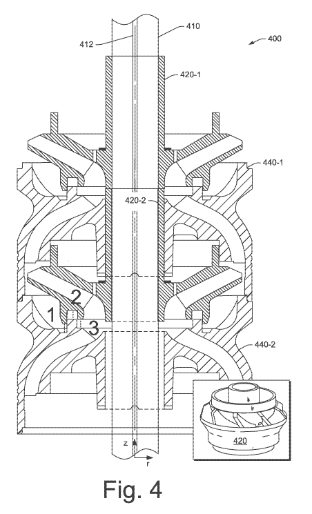
[0045] Fig. 4 shows a cutaway view of an assembly 400 that includes a
shaft
410 with a keyway 412 that may be fit with a key where components are stacked
along the shaft 410. As shown in the example of Fig. 4, the components include
an
impeller 420-1, a diffuser 440-1, another impeller 420-2 and another diffuser
440-1.
Fig. 4 also shows a perspective view of an impeller 420. In the example of
Fig. 4,
the impellers 420-1 and 420-2 may contact each other, for example, directly
along
hub portions or, for example, indirectly via a hub spacer (e.g., an impeller
spacer).
As shown, the diffusers 440-1 and 440-2 may contact each other, for example,
directly along outer wall portions or, for example, indirectly via a diffuser
spacer.
[0046] During operation, the assembly 400 acts to drive fluid in an upward
direction, for example, axially upwardly with respect to the shaft 410. In an
individual
stage formed by an impeller and a diffuser, flow of fluid may be "mixed" with
respect
7
CA 02939019 2016-08-05
WO 2015/123236
PCT/US2015/015314
to direction. For example, fluid may flow radially as well as axially due to
configuration of an impeller and a diffuser in a stage.
[0047] Fig. 4 shows four axial clearances between the impeller 420-2 and
the
diffuser 440-2, which are labeled 1, 2 and 3, moving from an outer radial
position to
an inner radial position.
[0048] Fig. 5A shows an enlarged cutaway view of a portion of the assembly
400 of Fig. 4. As shown in Fig. 5A, the impeller 420 includes an inner surface
421 at
an inner radius (e.g., an inner diameter) and an outer surface 429 at an outer
radius
(e.g., an outer diameter). The impeller 420 includes vanes or blades 423 that
extend
from a leading edge 422 to a trailing edge 424. During operation, as the
impeller
420 rotates (e.g., due to the impeller 420 being operatively coupled to the
shaft 410),
fluid flows in throats defined by adjacent vanes 423 from the leading edge 422
to the
trailing edge 424. Also shown in the example of Fig. 5A are a component 472,
which
may be a thrust washer, and a passage 425 in the impeller 420, which may be a
pressure balancing passage. The component 472 may be an annular component
(e.g., a washer) that sits on a shoulder of the impeller 420 and the impeller
420 may
include a plurality of passages such as the passage 425 (see, e.g., the
perspective
view of the impeller 420 of Fig. 4).
[0049] As shown in Fig. 5A, the diffuser 440 includes an inner surface 441
at
an inner radius (e.g., an inner diameter) and an outer surface 449 at an outer
radius
(e.g., an outer diameter). As indicated by dashed lines, another impeller
(e.g., a hub
portion) or an impeller spacer may be disposed proximate to the inner surface
441 of
the diffuser 440. Between the inner and outer radii, the diffuser 440 includes
vanes
or blades 443 that extend from a leading edge 442 (see upper diffuser) to a
trailing
edge 444 (see lower diffuser). In the example of Fig. 5A, during operation,
the
diffuser 440, configured to be substantially statically disposed in a housing
(e.g., in a
diffuser stack), can direct flow of fluid to the leading edges 422 of the
vanes 423 of
the impeller 420. Specifically, the leading edge of the vanes 443 of the
diffuser 440
may receive fluid from a lower impeller such that fluid is directed in throats
defined
by adjacent vanes 443 of the diffuser 440 toward the trailing edges 444 of the
vanes
443 of the diffuser 440 and then onward toward leading edges 422 of the vanes
423
of the impeller 420.
[0050] Fig. 5B shows an enlarged cutaway view of a portion of an assembly
similar to that shown in Fig. 4. As shown in Fig. 5B, the impeller 420'
includes an
8
CA 02939019 2016-08-05
WO 2015/123236
PCT/US2015/015314
inner surface 421' at an inner radius (e.g., an inner diameter) and an outer
surface
429' at an outer radius (e.g., an outer diameter). The impeller 420' includes
vanes or
blades 423' that extend from a leading edge 422' to a trailing edge 424'.
During
operation, as the impeller 420' rotates (e.g., due to the impeller 420' being
operatively coupled to the shaft 410'), fluid flows in throats defined by
adjacent vanes
423' from the leading edge 422' to the trailing edge 424'. Also shown in the
example
of Fig. 5B are a component 472', which may be a thrust washer, and a passage
425'
in the impeller 420', which may be a pressure balancing passage. The component
472' may be an annular component (e.g., a washer) that sits on a shoulder of
the
impeller 420' and the impeller 420' may include a plurality of passages such
as the
passage 425' (see, e.g., the perspective view of the impeller 420 of Fig. 4).
[0051] As shown in Fig. 5B, the diffuser 440' includes an inner surface
441' at
an inner radius (e.g., an inner diameter) and an outer surface 449' at an
outer radius
(e.g., an outer diameter). As indicated by dashed lines, another impeller
(e.g., a hub
portion) or an impeller spacer may be disposed proximate to the inner surface
441'
of the diffuser 440'. Between the inner and outer radii, the diffuser 440'
includes
vanes or blades 443' that extend from a leading edge 442' (see upper diffuser)
to a
trailing edge 444' (see lower diffuser). In the example of Fig. 5B, during
operation,
the diffuser 440', configured to be substantially statically disposed in a
housing (e.g.,
in a diffuser stack), can direct flow of fluid to the leading edges 422' of
the vanes
423' of the impeller 420'. Specifically, the leading edge of the vanes 443' of
the
diffuser 440' may receive fluid from a lower impeller such that fluid is
directed in
throats defined by adjacent vanes 443' of the diffuser 440' toward the
trailing edges
444' of the vanes 443' of the diffuser 440' and then onward toward leading
edges
422' of the vanes 423' of the impeller 420'.
[0052] In Figs. 5A and 5B, arrows show a general direction of fluid flow,
for
example, where such fluid flows radially inwardly in diffuser throats and
radially
outwardly in impeller throats while progressing axially upwardly.
[0053] Returning to Fig. 5A, impeller 420 includes lower surfaces 431, 432,
433, 434, 435, 436 and 437. Referring to the diffuser 440, it includes upper
surfaces
451, 452, 453, 454, 455, 456 and 457. The surfaces 432 and 452, 433 and 453,
434
and 454, 435 and 455 and 436 and 456 may be opposing surfaces while the
surfaces 437 and 457 may be surfaces that define, at least in part, an outer
chamber
480. During operation, the outer chamber 480 may be a high pressure chamber
9
CA 02939019 2016-08-05
WO 2015/123236
PCT/US2015/015314
when compared to an inner chamber 460, which exists radially between the shaft
410 and a ridge 446 of the diffuser 440 and axially between the trailing edges
444 of
the vanes 443 of the diffuser 440 and the leading edges 422 of the vanes 423
of the
impeller 420. In the example of Fig. 5A, an intermediate chamber 426 exists,
for
example, as defined by the surfaces 433, 434 and 435 of the impeller 420 and
the
surface 454 of the ridge 446 of the diffuser 440.
[0054] In Fig. 5B, impeller 420' includes lower surfaces 431', 432', 433',
434',
435', 436' and 437'. Referring to the diffuser 440', it includes upper
surfaces 451',
452', 453', 454', 455', 456' and 457'. The surfaces 432' and 452', 433' and
453',
434' and 454', 435' and 455' and 436' and 456' may be opposing surfaces while
the
surfaces 437' and 457' may be surfaces that define, at least in part, an outer
chamber 480'. During operation, the outer chamber 480' may be a high pressure
chamber when compared to an inner chamber 460', which exists radially between
the shaft 410' and a ridge 446' of the diffuser 440' and axially between the
trailing
edges 444' of the vanes 443' of the diffuser 440' and the leading edges 422'
of the
vanes 423' of the impeller 420'. In the example of Fig. 5B, an intermediate
chamber
426' exists, for example, as defined by the surfaces 433', 434' and 435' of
the
impeller 420' and the surface 454' of the ridge 446' of the diffuser 440'.
[0055] As mentioned with respect to Fig. 4, various clearances exist,
which
are labeled 1, 2 and 3. As shown in Fig. 5A, these clearances correspond to
opposing surfaces 436 and 456 (clearance 1), 434 and 454 (clearance 2) and 432
and 452 (clearance 3), respectively. As shown, the clearance 1 is associated
with
the outer chamber 480, the clearance 2 is associated with the intermediate
chamber
426 and the clearance 3 is associated with the inner chamber 460. As shown in
Fig.
5B, these clearances correspond to opposing surfaces 436' and 456' (clearance
1),
434' and 454' (clearance 2) and 432' and 452' (clearance 3), respectively. As
shown, clearance 1 is associated with the outer chamber 480', the clearance 2
is
associated with the intermediate chamber 426' and the clearance 3 is
associated
with the inner chamber 460'.
[0056] Fig. 6A shows a cutaway view of a portion of the assembly 400 of
Figs.
4 and 5A along with a cutaway view of a portion of an assembly 600, which
includes
a shaft 610, an impeller 620 and a diffuser 640. As shown in Fig. 6A, the
impeller
620 includes a leading edge 622 of a vane and surfaces 631, 632, 634 and 636.
As
shown in Fig. 6A, the diffuser 640 includes a trailing edge 644 of a vane,
surfaces
CA 02939019 2016-08-05
WO 2015/123236
PCT/US2015/015314
651, 652, 654 and 656 and a ridge 646, which may be defined by, for example,
an
inner radius, an outer radius and an axial height. The various surfaces may
define,
at least in part, respective chambers, including an inner chamber 660, an
intermediate chamber 626 and an outer chamber 680. During operation of the
assembly 600, in general, the outer chamber 680 has a higher fluid pressure
than
the inner chamber 660 (e.g., through which fluid flows from throats of the
diffuser
640 to throats of the impeller 620).
[0057] A comparison of the chambers 480, 426 and 460 of the assembly 400
to the chambers 680, 626 and 660 of the assembly 600 shows that the assembly
600 has a larger outer chamber, an axially deeper intermediate chamber and an
inner chamber that may have one or more different dimensions.
[0058] As to the outer chamber 680, it is enlarged compared to the outer
chamber 480 by positioning of the ridge 646 radially inward towards the inner
chamber 660. As an example, the ridge 646 may act to form a seal with respect
to
the intermediate chamber 626, for example, along an inner radius of the ridge
646
and an inner radius of the intermediate chamber 626. As the assembly 600 has a
larger outer chamber, which may be considered a high fluid pressure chamber,
the
assembly 600 may be more "balanced" with respect to forces that may act upon
the
components.
[0059] As to the dimensions of the intermediate chamber 626 and the ridge
646, these may be selected as to a "piston" effect. For example, the ridge 646
may
be considered as an annular piston that is received in an annular chamber. In
such
an example, fluid in the annular chamber may be compressed by movement of the
ridge 646 axially into the annular chamber; noting that during operation, the
walls
that define the annular chamber rotate (e.g., as driven by the impeller 620
being
operatively coupled to the shaft 610). As the ridge 646 progresses axially
into the
intermediate chamber 626 (e.g., by axial movement of the impeller 620, the
diffuser
640 or both the impeller 620 and the diffuser 640), compression of fluid
trapped in
the intermediate chamber 626 may increase pressure forces that can counteract
the
one or more forces that are acting to cause the progression of the ridge 646.
As an
example, the "piston" effect may be tailored based on clearances between
surfaces
of the impeller 620 that define, in part, the intermediate chamber 626 and
surfaces of
the ridge 646 of the diffuser 640.
11
CA 02939019 2016-08-05
WO 2015/123236
PCT/US2015/015314
[0060] Fig. 6B shows a cutaway view of a portion of an assembly similar to
that shown in Figs. 4 and 5B along with a cutaway view of a portion of an
assembly
600', which includes a shaft 610', an impeller 620' and a diffuser 640'. As
shown in
Fig. 6B, the impeller 620' includes a leading edge 622' of a vane and surfaces
631',
632', 634' and 636'. As shown in Fig. 6B, the diffuser 640' includes a
trailing edge
644' of a vane, surfaces 651', 652', 654' and 656' and a ridge 646', which may
be
defined by, for example, an inner radius, an outer radius and an axial height.
The
various surfaces may define, at least in part, respective chambers, including
an inner
chamber 660', an intermediate chamber 626' and an outer chamber 680'. During
operation of the assembly 600', in general, the outer chamber 680' has a
higher fluid
pressure than the inner chamber 660' (e.g., through which fluid flows from
throats of
the diffuser 640' to throats of the impeller 620').
[0061] A comparison of the chambers 480', 426' and 460' of the assembly
400' to the chambers 680', 626' and 660' of the assembly 600' shows that the
assembly 600' has a larger outer chamber, an axially deeper intermediate
chamber
and an inner chamber that may have one or more different dimensions.
[0062] As to the outer chamber 680', it is enlarged compared to the outer
chamber 480' by positioning of the ridge 646' radially inward towards the
inner
chamber 660'. As an example, the ridge 646' may act to form a seal with
respect to
the intermediate chamber 626', for example, along an inner radius of the ridge
646'
and an inner radius of the intermediate chamber 626'. As the assembly 600' has
a
larger outer chamber, which may be considered a high fluid pressure chamber,
the
assembly 600' may be more "balanced" with respect to forces that may act upon
the
components.
[0063] As to the dimensions of the intermediate chamber 626' and the ridge
646', these may be selected as to a "piston" effect. For example, the ridge
646' may
be considered as an annular piston that is received in an annular chamber. In
such
an example, fluid in the annular chamber may be compressed by movement of the
ridge 646' axially into the annular chamber; noting that during operation, the
walls
that define the annular chamber rotate (e.g., as driven by the impeller 620'
being
operatively coupled to the shaft 610'). As the ridge 646' progresses axially
into the
intermediate chamber 626' (e.g., by axial movement of the impeller 620', the
diffuser
640' or both the impeller 620' and the diffuser 640'), compression of fluid
trapped in
the intermediate chamber 626' may increase pressure forces that can counteract
the
12
CA 02939019 2016-08-05
WO 2015/123236
PCT/US2015/015314
one or more forces that are acting to cause the progression of the ridge 646'.
As an
example, the "piston" effect may be tailored based on clearances between
surfaces
of the impeller 620' that define, in part, the intermediate chamber 626' and
surfaces
of the ridge 646' of the diffuser 640'.
[0064] As an example, a pump may include one or more dimensions that
provide for clearances. As an example, such clearances may be defined with
respect to a diameter of a pump, for example, an outer diameter of a pump. As
an
example, such clearances may be gaps between components, for example, gaps
between an impeller and a diffuser, which may be, for example, axial gaps. For
example, Table 1 below illustrates an example of clearances (e.g., minimum
gap)
between an impeller and a diffuser with respect to pump outer diameter.
[0065] Table 1
Examples of minimum gap between impeller and diffuser (inch)
Pump OD Gap El Gap E2 Gap E3 Gap E4 Gap E5 Gap E6 Gap E7
<4.50" 0.085 0.095 0.12 0.15 0.18 0.21 0.25
4.5 to 5.5" 0.085 0.095 0.12 0.15 0.18 0.21 0.25
>5.5" 0.095 0.105 0.135 0.165 0.195 0.225 0.25
[0066] As indicated in Table 1, a specified minimum gap may increase with
respect to increasing outer diameter of a pump. In Table 1, seven examples are
given with respect to criteria as to pump outer diameter. The values therein
may be
considered ranges, for example, where each example includes values within the
ranges. As an example, the gaps given in Table 1 may represent gaps between
material of an impeller and material of an adjacent diffuser, for example,
without a
washer that may be disposed therebetween (e.g., in a pump assembly). As an
example, an impeller and/or a diffuser may be made of metal, alloy, ceramic or
other
material. As an example, a pump may be defined in part by a minimum impeller
to
diffuser gap (e.g., consider "2" in Fig. 4), which may be defined based at
least in part
on outer diameter of a pump. As an example, a pump may be defined based at
least
in part on an axial height of a feature of component (e.g., a ridge) and/or an
axial
depth of a feature of a component (e.g., a slot). In a pump, as assembled,
such
components may be arranged according to a minimum gap, as an axial distance
between a surface of a feature of one component (e.g., a ridge of an impeller)
and a
surface of a feature of another component (e.g., a slot of a diffuser).
13
CA 02939019 2016-08-05
WO 2015/123236
PCT/US2015/015314
[0067] As an example, a pump may include stages that include one or more
slot aspect ratios. As an example, a pump may include one or more thrust
washers,
which may be considered "wide" thrust washers, for example, that may be
implemented for a particular slot aspect ratio (e.g., consider a slot aspect
ratio of
about 1). As an example, as to slot aspect ratio or ratios, a pump may include
one
or more ratios that depend on an outer diameter or other dimension of a pump.
For
example, as explained with respect to Table 1, clearances, gaps, etc. may be
specified with respect to a dimension such as outer diameter of a pump.
[0068] As an example, a pump may include one or more dimensions that
provide for clearances. As an example, such clearances may be defined with
respect to a diameter of a pump, for example, an outer diameter of a pump. As
an
example, such clearances may be gaps between components, for example, gaps
between an impeller and a diffuser, which may be for example, axial gaps. For
example, an axial gap may be the distance between surfaces 434' and 454' in
Fig.
5B. For example, Table 2 below illustrates an example of clearances (e.g.,
minimum
gap) between an impeller and a diffuser with respect t pump outer diameter.
[0069] Table 2
Examples of minimum gap between impeller and diffuser (inch)
Gap Gap Gap Gap Gap
Pump OD Gap E8 Gap E9 E10 E11 E12 E13 E14
<4.50" 0.2125 0.2375 0.30 0.375 0.45 0.525 0.625
4.5 to 5.5" 0.2125 0.2375 0.30 0.375 0.45 0.525 0.625
>5.5" 0.2375 0.2625 0.3375
0.4125 0.4875 0.5625 0.625
[0070] As indicated in Table 2, a specified minimum gap may increase with
respect to increasing outer diameter of a pump. In Table 2, seven examples are
given with resepct to criteria as to puter pump diameter. The values therein
may be
considered ranges, for example, where each example include values within the
ranges. As an example, the gaps given in Table 2 may represent gaps between
material of an impeller and material of an adjacent diffuser. As an example, a
pump
may be defined based at least in part of an axial height of a feature of a
component
(e.g., a ridge) and/or an axial depth of a feature of a component (e.g., a
slot). In a
pump, as assembled, such components may be arranged according to a minimum
gap, as an axial distance between a surface of a feture of one component
(e.g., a
14
CA 02939019 2016-08-05
WO 2015/123236
PCT/US2015/015314
ridge of an impeller) and a surface of a feature of another component (e.g., a
slot of
a diffuser). As an example, the minimum gap (e.g., any of Gap El ¨ E14) may
relate
to the distance between surface 434 of impeller 420 and surface 454 of
diffuser 440,
as shown in Fig. 5A, or between surface 434' of impeller 420' and surface 454'
of
diffuser 440', as shown in Fig. 5B.
[0071] Fig. 7 shows a top view and a perspective view of components of an
assembly 700. In Fig. 7, the top view shows an impeller 720 that includes a
cutout
727 along an inner surface that can accept a portion of a key 716 that is
seated with
respect to a shaft 710. Also shown are a series of passages 725, which may act
to
balance pressure. In Fig. 7, the perspective view shows the impeller 720 with
respect to a spacer 790 that includes a tongue 793 with side recesses 791,
which
may allow for side-to-side flexing of the tongue 793 with respect to the
spacer 790.
As shown, the tongue 793 is received by a slot 739 of the impeller 720. The
tongue
793 as received by the slot 739 may provide for transmission of torque from
the
spacer 790 to the impeller 720. For example, the spacer 790 may include a
keyway
795 for receipt of the key 715 to thereby rotate the spacer 790 responsive to
rotation
of the shaft 710. In such an arrangement, torque may be transferred to the
impeller
720 via the tongue 793 where, for example, the cutout 727 may reduce contact
between the impeller 720 and the key 715. Where the key 715 is made of a hard
metal (e.g., or alloy) and the impeller 720 is made of ceramic (e.g.,
composite
material, etc.), the features may help avoid damage to the impeller 720 by the
key
715.
[0072] As mentioned, an impeller may include one or more balance passages,
for example, that couple an interior space of an impeller to an exterior
space, for
example, defined by the impeller and an adjacent diffuser. In the example of
Fig. 7,
fluid may flow from an opening of the passage 725 as shown in the perspective
view
of the impeller 720 to an opening of the passage 725 as shown in the top view
of the
impeller 720.
[0073] Fig. 8 shows a cutaway view of an impeller 820 that includes a
cylindrical wall between an inner surface 821 at an inner radius and an outer
surface
823 at an outer radius. The cylindrical wall may be referred to as a hub, for
example,
from which portions of the impeller 820 extend radially outwardly. As an
example, a
hub may experience certain axial forces that are not directly experienced by
other
portions of the impeller 820. As an example, a hub or a portion of a hub of an
CA 02939019 2016-08-05
WO 2015/123236
PCT/US2015/015314
impeller may be made of a material that has a stiffness that may be greater
than that
of other portions of the impeller 820. For example, where an impeller is
formed of a
ceramic, the ceramic may be modified (e.g., via an additive, via fibers, via
particles,
via chemical treatment, via heat treatment, etc.) to form the impeller with a
higher
stiffness along the hub.
[0074] As an example, an impeller may include a hub where the hub may be
an integral hub of an impeller formed as a unitary component. As an example,
an
impeller may include a truncated hub, for example, for use with a hub spacer
that
may be made of a material that is stiffer than the material from which the
truncate
hub is made. As an example, a hub spacer may be made of a material such as,
for
example, SS304 or a ceramic. As an example, an impeller (e.g., a truncated
impeller) may be formed of a material such as, for example, Ni-resist (e.g.,
cast iron
that includes graphite in a matrix of austenite).
[0075] Fig. 9 shows an example of a ring 915 that may be used in an
assembly such as the example assembly 901 or the example assembly 903. The
ring 915 may be a tolerance ring and may be configured with outwardly facing
features (e.g., "BN"), inwardly facing features (e.g., "AN") or a combination
of
outwardly facing features and inwardly facing features. In the assembly 901,
the
rings 915 include inwardly facing features that are disposed between a
component
and a shaft of the assembly 901. In the assembly 903, the rings 915 include
inwardly facing features that are disposed between a component and a shaft of
the
assembly 903.
[0076] As an example, impellers may be frictionally coupled to a pump shaft
so that the impellers can slide to achieve proper axial location relative to
diffusers
during pump assembly. In such an example, the frictional force between the
impellers and shaft may be selected to be greater than an impeller axial force
so
that, during operation, the impeller axial may be transferred to, for example,
a
protector bearing or other structure of an assembly. Such an approach may be
considered to be, as an example, a hybrid approach with various
characteristics of a
floater construction and various characteristics of a compression
construction.
[0077] As example, a tolerance ring with an inner diameter of about 0.69
inch
and a maximum diameter of about 0.75 inch may be used in an assembly that
includes a shaft with an outer diameter of about 0.69 inch. As an example, an
assembly may include tolerance rings, for example, as an alternative to key
and
16
CA 02939019 2016-08-05
WO 2015/123236
PCT/US2015/015314
shaft keyway for torque transmission (e.g., where each impeller includes a
tolerance
ring or rings as shown in the assembly 901).
[0078] Fig. 10 shows a cutaway view of an example of an assembly 1000 that
includes three stages where each stage includes an impeller 1020, a first hub
spacer
1030, a diffuser 1040 and a second hub spacer 1050.
[0079] Fig. 11 shows a cutaway view of a portion of the assembly 1000 of
Fig.
10. As shown, the first hub spacer 1030 includes an inner diameter and an
outer
diameter and the second hub spacer 1050 includes an inner diameter and an
outer
diameter where the outer diameter of the first hub spacer exceeds the outer
diameter
of the second hub spacer 1050. In such an example, a diffuser pad 1060 (e.g.,
an
thrust washer, etc.) may be located as far inboard, for example, near a
diffuser exit
to allow for an increased diameter hub spacer.
[0080] In the assembly 1000, the stiffnesses of components forming the hub
stack may be selected using appropriate materials. Such an approach may, for
example, relax or alleviate material constraints as to impeller hub diameter,
for
example, such that impeller stiffness may be enhanced.
[0081] As an example, the diffuser pad 1060 of Fig. 11 may be a non-
contact
surface (e.g., contact may be controlled by a ring region, near the flow
passage
area).
[0082] In the example of Fig. 11, the diffuser bore may be stepped to
include a
smaller bore portion and a larger bore portion, for example, where the larger
bore
portion may accommodate a larger impeller hub.
[0083] As an example, one or more components may be made with desired
stiffness properties. For example, a spacer may be constructed with a
compliance
and, for example, a system may include spacers with different compliances. As
an
example, over a length of a system, component compliance may vary, for
example,
from one axial end to another axial end. As an example, over a length of a
system
component stiffness may vary, for example, from one axial end to another axial
end.
[0084] As an example, a system that includes diffusers may include
diffusers
with different stiffness values. For example, a diffuser at a lower end of a
stack may
have a stiffness value that differs from that of a diffuser at an upper end of
the stack.
[0085] As an example, a system that includes impellers and impeller
spacers
may include impellers and/or impeller spacers with different compliance
values. For
example, an impeller and/or an impeller spacer at a lower end of a stack may
have a
17
CA 02939019 2016-08-05
WO 2015/123236
PCT/US2015/015314
compliance value that differs that of an impeller and/or an impeller spacer at
an
upper end of the stack.
[0086] As an example, a system may include multiple pumps, for example,
where each pump is operatively coupled to a shaft of another pump (e.g., or
pumps).
In such a system, characteristics of the pumps may differ. For example, a
lower
pump may differ from an upper pump as to, for example, characteristics of
diffusers,
impellers and/or impeller spacers.
[0087] As to compliance and stiffness, stiffness may characterize rigidity
of a
component, for example, an extent to which it resists deformation in response
to an
applied force and, for example, compliance may be the inverse of stiffness and
given
in, for example, meters per newton. As an example, stiffness and/or compliance
may be measured when a component is subject to a particular force or forces.
Such
measurements may be made, for example, at specified temperatures, specified
history of a component (e.g., service age, etc.), specified lubricating
conditions,
specified rotational conditions, etc. For example, an axial stiffness of a
rotating
component may be measured with respect to an applied axial force while the
component is rotating at a particular rotational speed (e.g., rpm, etc.). As
an
example, stiffness may be stated with respect to applied force and operational
limits
(e.g., one or more rotational speeds, etc.). As an example, depending on
rotational
speed, a component may expand radially and, for example, contract axially. In
such
an example, stresses and strains associated with rotation may be taken into
account
when selecting a material of construction for a component and/or a shape of a
component.
[0088] As an example, a component may be made of a material that is
characterized in part by its elastic modulus (e.g., an intensive property
whereas
stiffness may be referred to as an extensive property). As an example, a
material of
construction with a high modulus of elasticity may be used where deflection is
undesirable and a material of construction with a lower modulus of elasticity
may
provide for increased flexibility. As an example, shape, boundary forces,
contact
areas, etc. may be considered when constructing a component and, for example,
selecting one or more material properties for the component.
[0089] Fig. 12 shows an example of an assembly 1200 that includes three
diffusers 1240-1, 1240-2 and 1240-3 where the diffusers 1240-1 and 1240-3
include
passages 1241 and 1243 at an outer radius. As shown, the diffusers 1240-1 and
18
CA 02939019 2016-08-05
WO 2015/123236
PCT/US2015/015314
1240-3 may include an annular channel 1244, for example, configured to receive
a
seal element 1274 or seal elements. As an example, a housing may be positioned
about the assembly 1200 such that the seal element 1274 forms a seal to seal
an
upper annular passage and a lower annular passage. Fluid may flow via such
annular passages, for example, to help balance fluid pressures.
[0090] As shown in the example of Fig. 12, the diffuser 1240-2 includes a
wall
profile that differs from that of the diffusers 1240-1 and 1240-3. For
example, the
wall profile of the diffuser 1240-2 may include an inwardly extending portion
that may
act to form a clearance with an outer portion of an impeller. For example, the
profile
of a diffuser may be selected to achieve a clearance with respect to an
impeller (e.g.,
to optionally control flow in, to or from a region, a chamber, etc.). A
diffuser may
include an increased diffuser wall thickness in one or more stages, for
example, to
minimize the gap between an impeller tip and a diffuser wall. As an example,
stages
may differ, for example, as shown in Fig. 12. As an example, such an approach
may
provide for particular flow, pressure balancing, etc. in a series of stages.
[0091] As an example, a multistage centrifugal pump can include stages
where an individual stage may include an impeller and a diffuser. Such a
multistage
centrifugal pump may include a stack of stages or stacks of stages (e.g.,
stacked
along a common axis). As an example, in a compression pump or compression ring
pump, individual impellers hubs and diffusers shoulders may be compressed, for
example, using a compression nut and a grooved spacer tube, respectively. For
example, a compression nut may act to compress a stack of impeller hubs and a
grooved spacer tube may act to compress a stack of diffusers. As an example, a
grooved spacer tube for a stack of diffusers may be a cylindrical wall that
may
include tangential overlapping slots. In an assembly, such a grooved spacer
tube
may act to hold diffusers in place and reduce risk of rotation of one or more
of the
diffusers (e.g., to prevent diffuser spinning).
[0092] As an example, techniques to compress diffusers may aim to address
effects of thermal phenomena, for example, consider thermal expansion and
contraction of materials in an assembly where the materials may have different
thermal expansion coefficients (e.g., the thermal expansion coefficient for
aluminum
oxide ceramics is approximately two and a half times less than the thermal
expansion coefficient for steel). As an example, consider a pump section with
a
housing length of about 6 m assembled at a temperature of about 20 degrees C
that
19
CA 02939019 2016-08-05
WO 2015/123236
PCT/US2015/015314
is positioned in a downhole environment at a temperature of about 120 degrees
C.
In such an example, for a stack of ceramic diffusers in a carbon steel
housing,
thermal expansion may result in a length difference between the stack and the
housing of the order of several millimeters because the housing expands
axially
more than the stack. The length difference may contribute to a decline in
compression force and, depending on the initial stack compression force and
housing elongation during assembly, preloading force may drop to an extent
that
diffusers may become loose (e.g., increasing the risk of diffuser rotation).
[0093] As an example, an assembly may include diffusers arranged in a stack
that has compliance (e.g., the stack may "float" in a housing). For example,
one or
more components may be included in the assembly where the one or more
components allow the diffusers to translate axially. In such an example,
translation
of the diffusers in the assembly may track translation of impellers (e.g., if
the
impellers translate). Such an approach may act to maintain axially alignment
between diffusers and impellers.
[0094] In addition to compression-style pumps, for example, in which
impeller
downthrust force may be transferred to a thrust bearing located in a protector
(see,
e.g., the protector 217 of Fig. 2), floater-style pumps may include impellers
that are
not clamped or compressed but "float" (e.g., freely along a shaft). As an
example,
individual impellers in floater-style pump may transfer impeller downthrust to
respective diffusers (e.g., where shaft downthrust is still transferred to a
thrust
bearing in a protector). As an example, a multi-pump string may include stages
that
are compression-style or floater-style. However, in the case where it is
advantageous to use a compression-style pump, like for instance in abrasive
service,
but the total downthrust of the string may be excessive, a hybrid string of
compression-style pumps located at the bottom of a string and floater-style
pumps at
a top of a string could be used. As an example, a pump string may include
compression-style and floater-style equipment, which may be optionally
arranged
with respect to one or more of an intended direction of impeller rotation,
impeller
speed, power, head, gravity, etc. As an example, a string may include shafts
of
pump units in axial contact to transfer shaft thrust load to a protector
where, for
example, impellers of floater-style pump units may not be compressed or
clamped,
but rather "float" axially (e.g., as is in a floater-style pump construction).
CA 02939019 2016-08-05
WO 2015/123236
PCT/US2015/015314
[0095] Fig. 13 shows an example of an assembly 1300 that includes opposing
axial ends 1302 and 1304 and a shaft 1306 operatively coupled to a stack of
impellers 1320-1 to 1320-N. The assembly 1300 also includes a housing 1310 and
a
stack of diffusers 1340-1 to 1340-N.
[0096] In the example of Fig. 13, a coupling 1312 may be threaded to inner
threads of the housing 1310 to axially position the coupling 1312 with respect
to the
diffuser 1340-1. As shown, a compliant component 1392 is disposed between a
lower end of the coupling 1312 and an upper end of the diffuser 1340-1. As an
example, the compliant component 1392 may be characterized, at least in part,
by a
spring constant. As an example, the compliant component 1392 may be
constructed
with respect to one or more harmonics, for example, to diminish risk of
undesirable
harmonics during operation of the assembly 1300. As an example, the compliant
component 1392 may be constructed with one or more damping features that act
to
damp harmonic motion (e.g., a damper that acts to diminish risk of
oscillation).
[0097] In the example of Fig. 13, a coupling 1313 may be threaded to inner
threads of the housing 1310 to axially position the coupling 1313 with respect
to the
diffuser 1340-N, for example, and optionally one or more intermediate
components
1314 and 1316. As shown, a compliant component 1394 is disposed between an
upper end of the coupling 1313 and a lower end of the intermediate component
1314. As an example, the compliant component 1394 may be characterized, at
least
in part, by a spring constant. As an example, the compliant component 1394 may
be
constructed with respect to one or more harmonics, for example, to diminish
risk of
undesirable harmonics during operation of the assembly 1300. As an example,
the
compliant component 1394 may be constructed with one or more damping features
that act to damp harmonic motion (e.g., a damper that acts to diminish risk of
oscillation).
[0098] In the example of Fig. 13, the diffusers 1340-1 to 1340-N may
"float"
with respect to the housing 1310 via the compliant components 1392 and 1394.
As
an example, the compliant components 1392 and 1394 may optionally differ in
one
or more of their respective characteristics. For example, the compliant
component
1394 may have a spring constant that differs from that of the compliant
component
1392 (e.g., as the compliant component 1394 may experience a higher load
depending on orientation of the assembly 1300). As an example, the compliant
21
CA 02939019 2016-08-05
WO 2015/123236
PCT/US2015/015314
components 1392 and 1394 may be selected with one or more characteristics to
diminish risk of undesirable oscillations of the diffusers 1340-1 to 1340-N.
[0099] As an example, the compliant components 1392 and 1394 may be
loaded (e.g., pre-loaded during assembly of the assembly 1300). In such an
example, loading may be based in part on one or more of intended use of the
assembly 1300, expected environmental conditions to which the assembly 1300
may
be subjected to during use, number of diffusers, type of diffuser,
configuration of
diffuser spacers, number of impellers, type of impellers, configuration of
impellers,
configuration of impeller spacers, motor characteristics, an rpm limit or
limits, rpm
range, torque, etc.
[00100] As an example, during operation of the assembly 1300 (e.g., as a
pump), the lower diffuser 1340-N may rest on the lower compliant component
1394
(e.g., indirectly), which may allow the diffuser 1340-N to move downwards, for
example, due to hydraulic forces acting on one or more upper diffusers, one or
more
impeller interactions with one or more diffusers, etc.
[00101] As an example, one or more compliant components may be included in
an assembly to help manage thermal phenomena, risk of diffuser rotation, risk
of
inter-component axial gaps, etc.
[00102] Fig. 14 shows an example of an assembly 1400 that includes opposing
axial ends 1402 and 1404 and a shaft 1406 operatively coupled to a stack of
impellers 1420-1 to 1420-N. The assembly 1400 also includes a housing 1410 and
a
stack of diffusers 1440-1 to 1440-N.
[00103] In the example of Fig. 14, the assembly 1400 may include one or
more
compliant components 1492, 1494, 1496 and/or 1498. As to the compliant
components 1492 and 1494, these may be, for example, the same or similar to
the
compliant components 1392 and 1394 of the assembly 1300 of Fig. 13.
[00104] As to the compliant components 1496 and 1498, these may be inter-
diffuser compliant components, for example, positioned axially intermediate
the
diffuser 1440-1 and the diffuser 1440-N. As shown, the compliant component
1496
is positioned axially below the diffuser 1440-1 and, for example, optionally
radially
outwardly from the impeller 1420-1. As an example, a diffuser 1440-2 may be
positioned axially below the compliant component 1496 such that the compliant
component 1496 is positioned and loaded between a surface of the diffuser 1440-
1
and a surface of the diffuser 1440-2. As shown in the example of Fig. 14, the
22
CA 02939019 2016-08-05
WO 2015/123236
PCT/US2015/015314
compliant component 1498 is positioned axially below the diffuser 1440-N-1 and
axially above the diffuser 1440-N.
[00105] As an example, the compliant components 1496 and 1498 may be
characterized, at least in part, by one or more spring constants. As an
example, the
compliant component 1496 and 1498 may be constructed with respect to one or
more harmonics, for example, to diminish risk of undesirable harmonics during
operation of the assembly 1400. As an example, the compliant component 1496
and/or the compliant component 1498 may be constructed with one or more
damping features that act to damp harmonic motion (e.g., a damper that acts to
diminish risk of oscillation).
[00106] In the example of Fig. 14, the diffusers 1440-1 to 1440-N may
"float"
with respect to the housing 1410 via one or more compliant components such as,
for
example, one or more of the compliant components 1492, 1494, 1496 and 1498;
noting that the assembly 1400 may optionally include more than one
intermediate
compliant component.
[00107] As an example, the compliant components 1496 and 1498 may
optionally differ in one or more of their respective characteristics. For
example, the
compliant component 1498 may have a spring constant that differs from that of
the
compliant component 1496 (e.g., as the compliant component 1498 may experience
a higher load depending on orientation of the assembly 1400). As an example,
the
compliant components 1496 and 1498 may be selected with one or more
characteristics to diminish risk of undesirable oscillations of the diffusers
1440-1 to
1440-N. As an example, where the assembly 1400 includes one or more of the
compliant components 1492 and 1494, one or more intermediate compliant
components (e.g., such as the compliant components 1496 and 1498) may be
selected with one or more characteristics to diminish risk of undesirable
oscillations
of the diffusers 1440-1 to 1440-N.
[00108] As an example, one or more compliant components may be loaded
(e.g., pre-loaded during assembly of an assembly). In such an example, loading
may be based in part on one or more of intended use of the assembly, expected
environmental conditions to which the assembly may be subjected to during use,
number of diffusers, type of diffuser, configuration of diffuser spacers,
number of
impellers, type of impellers, configuration of impellers, configuration of
impeller
spacers, motor characteristics, an rpm limit or limits, rpm range, torque,
etc.
23
CA 02939019 2016-08-05
WO 2015/123236
PCT/US2015/015314
[00109] As an example, one or more compliant components may be included in
an assembly to help manage thermal phenomena, risk of diffuser rotation, risk
of
inter-component axial gaps, etc. As an example, one or more compliant
components
may be included in an assembly such that diffusers are allowed to "float" and,
for
example, axially translate in a direction in which one or more impellers may
translate.
In such an example, diffusers may follow impellers with respect to axial
excursions
thereof within a housing.
[00110] As an example, a compliant component may be a spring. As an
example, a stack of diffusers may include one or more intermediate compliant
components. As an example, a compliant component may be positioned to directly
and/or indirectly contact a diffuser or diffusers.
[00111] As an example, an assembly may include one or more features of the
various examples described herein.
[00112] As an example, an assembly may include split rings on impellers. In
such an example, split rings may act to disaggregate forces experienced during
operation. For example, a split ring may act to transfer forces from an
impeller to a
shaft. As an example, a split ring may be used on a stage-by-stage or other
basis.
[00113] As an example, an assembly may include stiffer and shorter shafts
in
pump string. In such an example, stiffer shafts (or increased OD) for a pump,
an
intake and a protector may be used.
[00114] As an example, a method may include deploying multiple pumps where
each pump has a length that may experience a limited amount of force; for
example,
compared to a long pump that may experience more force, which may impact
performance, longevity, etc.
[00115] As an example, an assembly may include one or more Impeller hub
spacers with a relatively high thermal coefficient. In such an example,
impeller hub
spacers with high thermal coefficient may act to "lift" impellers upward,
which may
counteract various forces.
[00116] As an example, an assembly may include one or more impellers bolted
to a shaft. In such an example, impellers bolted to a shaft may transfer loads
from
the impellers to the shaft (e.g., to reduce deflections of an impeller).
[00117] As an example, an assembly may include a top thrust bearing
disposed
in a protector with a particular load capacity, for example, to match loads of
pinned
shafts.
24
CA 02939019 2016-08-05
WO 2015/123236
PCT/US2015/015314
[00118] As an example, a method may include operating an electric
submersible pump by delivering power to an electric motor to rotate a shaft
where
impellers of a pump are operatively coupled to the shaft. In such an example,
the
method may include protecting the electric motor using a protector disposed
axially
between the pump and the electric motor.
[00119] As an example, an electric submersible pump (ESP) can include a
shaft; an electric motor configured to rotatably drive the shaft; a housing; a
stack of
diffusers disposed in the housing; and impellers operatively coupled to the
shaft.
[00120] As an example, an ESP can include diffusers with ridges and
impellers
with slots where the ridges include a cross-sectional aspect ratio defined by
a ridge
width divided by a ridge height where the cross-sectional aspect ratio is less
than
approximately 1 (see, e.g., the slot 626 and the ridge 646 of the example of
Fig. 6A).
As an example, an ESP can include diffusers with ridges and impellers with
slots
where the slots include a cross-sectional aspect ratio defined by a slot width
divided
by a slot height where the cross-sectional aspect ratio is less than
approximately 1
(see, e.g., the slot 626 and the ridge 646 of the example of Fig. 6A).
[00121] As an example, an ESP can include diffusers with ridges and
impellers
with slots where the ridges include a cross-sectional ridge width and a ridge
height
where the ridge height exceeds the cross-sectional ridge width. As an example,
an
ESP can include diffusers with ridges and impellers with slots where the slots
include
a cross-sectional slot width and a slot height where the slot height exceeds
the
cross-sectional slot width.
[00122] As an example, an ESP can include impellers where each of the
impellers includes an inner annular lower surface adjacent to a slot adjacent
to an
outer annular lower surface where a cross-sectional dimension of the outer
annular
lower surface exceeds a cross-sectional dimension of the inner annular surface
(see,
e.g., the surface 632, the slot 626 and the surface 636 of the example of Fig.
6A). In
such an example, the outer annular lower surface may define, in part, an outer
chamber and the inner annular lower surface may define, in part, an inner
chamber
(see, e.g., the chambers 660 and 680 of the example of Fig. 6A). In such an
example, during operation of the ESP, the outer chamber may include a pressure
that exceeds a pressure of the inner chamber.
[00123] As an example, an ESP may include tolerance rings disposed between
impellers and shaft.
CA 02939019 2016-08-05
WO 2015/123236
PCT/US2015/015314
[00124] As an example, an ESP may include diffusers where at least one of
the
diffusers includes a stepped bore. In such an example, the stepped bore may
include a large diameter bore portion and a small diameter bore portion. In
such an
example, the ESP may include an impeller spacer, optionally integral with an
impeller (e.g., as a hub portion), that includes an outer diameter that
exceeds the
small diameter of the small diameter bore portion of the stepped bore.
[00125] As an example, a diffuser may include an annular face disposed
between a large diameter bore portion and a small diameter bore portion of the
diffuser. In such an example, an ESP may include a washer configured to abut
the
annular face.
[00126] As an example, an ESP can include an impeller spacer with an
annular
face and a diffuser with an annular face disposed between a large diameter
bore
portion and a small diameter bore portion of the diffuser. In such an example,
the
ESP may include a washer disposed on the annular face of the impeller spacer
(e.g.,
optionally integral to an impeller).
[00127] As an example, an ESP can include diffusers where at least one of
the
diffusers includes a passage disposed in an outer wall for passage of fluid to
a
clearance between the diffuser and a housing (e.g., where the clearance is
defined
in part by an outer surface of the diffuser and an inner surface of the
housing).
[00128] As an example, an ESP may include impellers where at least one of
the impellers includes at least one balance hole.
[00129] As an example, an ESP may include impellers where at least one of
the impellers includes a hub portion with a stiffness greater than a stiffness
of a hub
portion of another one of the impellers. As an example, an ESP may include
impellers, impeller spacers, etc. with different stiffnesses (e.g., arranged
along an
axis). In such an example, stiffness may vary, for example, where stiffness
for a
lower stage may differ from stiffness for an upper stage (e.g., where a lower
stage
may be subject to forces that differ from forces of the upper stage). As an
example,
an ESP may include impellers and/or impeller spacers with progressively
increasing
stiffness (e.g., from one end of a pump to another end of a pump). As an
example, a
pump may include components with greater stiffness at a lower end (e.g., a
fluid inlet
end) when compared to similar functioning components at an upper end (e.g., a
fluid
outlet end).
26
CA 02939019 2016-08-05
WO 2015/123236
PCT/US2015/015314
[00130] As an example, one or more control modules (e.g., for a controller
such
as the controller 230, the controller 250, etc.) may be configured to control
an ESP
(e.g., a motor, etc.) based at least in part on information as to one or more
fluid
circuits in that may exist between stages of a pump. For example, one or more
of
backspin, sanding, flux, gas lock or other operation may be implemented in a
manner that accounts for one or more fluid circuits (e.g., as provided by
diffusers
with fluid coupling holes). As an example, a controller may control an ESP
based on
one or more pressure estimations for a fluid circuit or circuits (e.g., during
start up,
transients, change in conditions, etc.), for example, where a fluid circuit or
circuits
may act to balance thrust force.
[00131] As an example, a controller may control an ESP based at least in
part
on one or more features of the ESP. For example, where an ESP includes one or
more compliant components (see, e.g., Figs. 13 and 14), the controller may
control
the ESP based at least in part on one or more characteristics of the one or
more
compliant components (e.g., spring constant(s), pre-load, load, number of
compliant
components, orientation of the ESP with respect to gravity in relationship to
one or
more of the compliant components, etc.). As an example, a controller may
include
an input for receipt of information about an ESP, which may include
information as to
features of the ESP that may act to position diffusers with respect to
impellers (e.g.,
axially), impellers with respect to diffusers (e.g., axially), etc. As an
example, power
delivered to an ESP may be ramped up, ramped down, limited, modulated, etc.
based at least in part on one or more features present in the ESP.
[00132] As an example, one or more methods described herein may include
associated computer-readable storage media (CRM) blocks. Such blocks can
include instructions suitable for execution by one or more processors (or
cores) to
instruct a computing device or system to perform one or more actions.
[00133] According to an embodiment, one or more computer-readable media
may include computer-executable instructions to instruct a computing system to
output information for controlling a process. For example, such instructions
may
provide for output to sensing process, an injection process, drilling process,
an
extraction process, an extrusion process, a pumping process, a heating
process, etc.
[00134] Fig. 15 shows components of a computing system 1500 and a
networked system 1510. The system 1500 includes one or more processors 1502,
memory and/or storage components 1504, one or more input and/or output devices
27
CA 02939019 2016-08-05
WO 2015/123236
PCT/US2015/015314
1506 and a bus 1508. According to an embodiment, instructions may be stored in
one or more computer-readable media (e.g., memory/storage components 1504).
Such instructions may be read by one or more processors (e.g., the
processor(s)
1502) via a communication bus (e.g., the bus 1508), which may be wired or
wireless.
The one or more processors may execute such instructions to implement (wholly
or
in part) one or more attributes (e.g., as part of a method). A user may view
output
from and interact with a process via an I/0 device (e.g., the device 1506).
According
to an embodiment, a computer-readable medium may be a storage component such
as a physical memory storage device, for example, a chip, a chip on a package,
a
memory card, etc.
[00135] According to an embodiment, components may be distributed, such as
in the network system 1510. The network system 1510 includes components 1522-
1, 1522-2, 1522-3, . . . 1522-N. For example, the components 1522-1 may
include
the processor(s) 1502 while the component(s) 1522-3 may include memory
accessible by the processor(s) 1502. Further, the component(s) 1502-2 may
include
an I/0 device for display and optionally interaction with a method. The
network may
be or include the Internet, an intranet, a cellular network, a satellite
network, etc.
Conclusion
[00136] Although only a few examples have been described in detail above,
those skilled in the art will readily appreciate that many modifications are
possible in
the examples. Accordingly, all such modifications are intended to be included
within
the scope of this disclosure as defined in the following claims. In the
claims, means-
plus-function clauses are intended to cover the structures described herein as
performing the recited function and not only structural equivalents, but also
equivalent structures. Thus, although a nail and a screw may not be structural
equivalents in that a nail employs a cylindrical surface to secure wooden
parts
together, whereas a screw employs a helical surface, in the environment of
fastening
wooden parts, a nail and a screw may be equivalent structures. It is the
express
intention of the applicant not to invoke 35 U.S.C. 112, paragraph 6 for any
limitations of any of the claims herein, except for those in which the claim
expressly
uses the words "means for" together with an associated function.
28