Note: Descriptions are shown in the official language in which they were submitted.
CA 02939227 2016-08-09
WO 2015/163910 PCT/US2014/035432
1
HYBRID ELECTRICAL AND
OPTICAL FIBER CABLE SPLICE HOUSINGS
CROSS REFERENCE TO RELATED APPLICATIONS
[0001] This application is related to the following two applications
filed the same
day as this application, which are both incorporated in this application in
their entireties
by reference: (1) Application Serial No. , for "Optical Fiber Splice
Housings," Park,
et al, inventors, attorney docket no. 61429-892258 and (2) Application Serial
No. , for
"Mounted Downhole Fiber Optics Accessory Carrier Body," Park, et al.,
inventors,
attorney docket no. 61429-896456.
FIELD OF THE INVENTION
[0002] This disclosure relates to fiber optic and electrical cables
utilized in oil and
other wells and other extreme environments and to splices and Y-connections of
such
cables.
BACKGROUND
[0003] Distributed fiber optic sensors and fiber optic cables are
commonly
clamped to the tubing or casing during run-in-hole (RIH). The cables are cut
at packers
and re-spliced once they are fed through the packers, or cut and spliced at
sensor
locations. Conventional practice is to take the cables and sensors to a cabin
with positive
pressure to remove any explosive gases, or to another safe area to prepare and
splice the
fibers/cables, and then take the finished assembly to the rig-floor and attach
the assembly
to a pre-manufactured gauge mandrel. The process of moving cables and system
components takes time, and rig-time is very expensive. Any reduction in rig-
time
therefore results in significant savings.
[0004] Electrical cables frequently are also utilized, introducing
additional issues
in handling and splicing.
[0005] Material and machining is expensive, and long linear splice
housings
require longer, more expensive mandrels to house them. The risk of damaging
splices is
lower if it is possible to utilize a smaller size completion with larger
clearance/drift
between tubing conveyed components and the casing inside diameter. A splice
housing
CA 02939227 2016-08-09
WO 2015/163910 PCT/US2014/035432
2
must be designed to survive bottom hole pressures, and the mandrel must be
designed to
survive bottom hole pressures during stimulation and production.
[0006] Existing splice housings therefore have a base and a lid or cover
of
substantial thickness because of bottom hole pressure. Many applications use a
tubular
linear splice housing for the splices, and Y-blocks are attached to the end of
the splice
housing to break out a fiber for a sensor such as a pressure sensor. The
length of the
splice and associated machined mandrels may be substantial, which increases
cost and
complexity. A longer machined mandrel requires a more expensive machine for
manufacturing, and the cost is therefore higher.
[0007] In existing linear splice configurations, the length of fiber in
the splice tray
is equivalent to the length of the pressure housing. The fiber is fixed at
each end of the
splice tray, usually with an adhesive like epoxy or room temperature
vulcanizing
("RTV") adhesive. As a result, when the splice housing is lowered in the well
bore, it
increases in temperature and expands, as does the fiber. However, the
coefficient of
expansion of the metal is typically an order of magnitude greater than the
fiber. As a
result, the fiber is stressed in tension, which can affect the optical
signals, and the fiber
can break.
BRIEF DESCRIPTION OF THE DRAWINGS
[0008] Illustrative embodiments are described in detail below with
reference to the
following drawing figures:
[0009] Figure 1 is an isometric view of a splice housing lid.
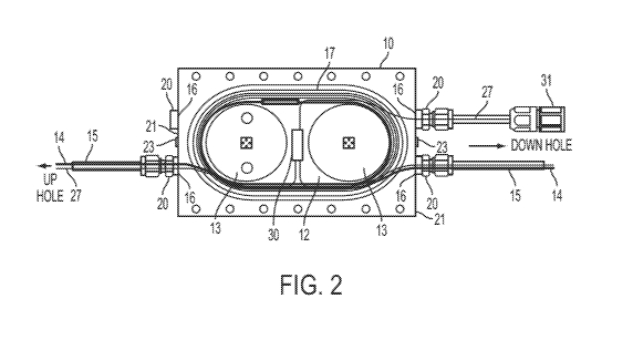
[0010] Figure 2 is a plan view of an alternative splice housing lid with
attached
compression fittings and electrical and optical fiber cable.
[0011] Figure 3 is a partially an exploded isometric view of the splice
housing lid
of Figure 2 together with an optional cover and C-seals but without the cables
shown in
Figure 2.
[0012] Figure 4 is another isometric view of the splice housing lid of
Figure 2
showing the other side of the lid.
[0013] Figure 5 is an isometric view of a portion of a solid, machined
mandrel to
which a splice housing lid may be attached.
CA 02939227 2016-08-09
WO 2015/163910 PCT/US2014/035432
3
[0014] Figure 6 is an isometric view of a modular mandrel assembly with
collars
securing a splice housing assembly and sensor cover on a section or length of
round
casing.
[0015] Figure 7 is an isometric view of a splice housing lid of this
disclosure
attached to a base having a curved outside surface.
DETAILED DESCRIPTION
[0016] The subject matter of embodiments of this patent is described here
with
specificity to meet statutory requirements, but this description is not
necessarily intended
to limit the scope of the claims. The claimed subject matter may be embodied
in other
ways, may include different elements or steps, and may be used in conjunction
with other
existing or future technologies. This description should not be interpreted as
implying any
particular order or arrangement among or between various steps or elements
except when
the order of individual steps or arrangement of elements is explicitly
described.
[0017] At high temperatures, current linear optical fiber splice housings
can
expand in length much more than the fiber due to differences in the thermal
expansion of
metal and glass. This creates stress in the fiber that can affect the optical
properties of the
signal, or in some cases, cause the fiber to break. Elimination of stress and
breakage and
increased splice reliability are key to the successful operation of down hole
fiber
telemetry.
[0018] A hybrid fiber optic and electrical splice housing may be used down
hole
with optical fibers and electrical conductors in one hybrid cable. The splice
housing may
be used for optical fiber splicing, electrical cable splicing, to connect
fiber optic sensors
and devices to optical fiber in FIMT (fiber in metal tube) or other optical
fiber and for
connecting electrical sensors and other devices to electrical cable wire.
Typical sensors
that may be connected with these devices and methods include pressure sensors,
flow
sensors and the like. The splice housing assemblies of this disclosure can
connect, among
others, end splices, through splices, single gauges, gauges and through
splices and two
gauges and through splices.
[0019] The splice chamber of this disclosure may be filled with fluid to
prevent
gel from the FIMTs travelling into the housing, which can also cause fiber
breakage
because the gel sometimes pulls fiber into the splice housing.
CA 02939227 2016-08-09
WO 2015/163910 PCT/US2014/035432
4
[0020] Incorporation of a Y-splitter in the same splice housing eliminates
multiple
connections and the need for a secondary housing. This simplifies and shortens
the
required structures, which reduces the length of the mandrel to which it is
mounted.
[0021] Other embodiments provide a modular mandrel and associated
hardware,
among other things, to simplify and shorten the design, to minimize cost, to
minimize rig
time, and to make a slimmer overall package than existing pressure gauge
mandrels and
splice hardware.
[0022] The splicing techniques and apparatus described here can make use
of a
zone-rated fiber optic splice kit and techniques. Because this apparatus can
hold a
sufficient length of fiber and wire cable in loops, there is sufficient length
to get the splice
joint in the raceway of this apparatus (described below), which is relatively
wide and tall
compared to a non-zone rated fusion splicer. In order to use a zone rated
splicer with a
linear splice housing, the linear splice housing would have to be much longer
than it is
currently, necessitating a longer mandrel to house it.
[0023] The splice housings of this disclosure utilize versatile splice
housing bodies
or "lids" usable with a variety of bases, mandrels and other structures to
form a splice
housing assembly within which splices and other structures are positioned and
to which
sensors and other devices may be attached. The housing assemblies of this
disclosure
may be used for end termination, pass through splices, gauge mounting and
combinations
of these. Splice housing assemblies could also be structured for the housing
body to be
formed in a mandrel or other base for use with a simpler cover. Such a
structure may,
however, be more difficult or expensive to manufacture and may forgo the
versatility of
incorporating the housing body cavity within the lid as described and
illustrated here.
[0024] The figures depict two exemplary splice housing lids. A first
embodiment
is shown as lid 8 in Figure 1. A second embodiment is depicted as lid 10 in
Figures 2, 3,
4, 6, and 7. Numerous other lid configurations in accordance with this
disclosure are
possible.
[0025] As shown in Figure 1, splice housing lid 8 has a flat mounting
surface 9, a
curved outer surface 11, and lid 8 defines an oval or oblong "raceway" 12
within which
fiber optic cable, electrical cable, splices, connections to sensors and other
similar
structures may be housed and protected when lid 8 is attached, typically with
machine
screws, to a base to form a splice housing assembly. Raceway 12 may have
alternative
CA 02939227 2016-08-09
WO 2015/163910 PCT/US2014/035432
shapes, including, without limitation, round and oval or oblong with different
proportions
than the exemplary proportions of those shown in the drawings.
[0026] Lid 10 (shown in Figures 2, 3, 4, 6, and 7) likewise utilizes an
oblong
raceway 12 but also includes two disks 13 around which cable can be wound. An
optional, simple plate-like cover (an example of which is shown as cover 29 in
Figure 3)
may be attached to the lid 8 or 10 to retain fiber and electrical cables
within the lid until
the lid and simple cover can be attached to a base.
[0027] When attached to a base such as base 26 shown in Figure 7, lids 8
and 10
provide an oval or oblong, pressure tight, optionally fluid-filled, enclosure
for fiber optic
cable 14 and electrical cable 27. The hybrid fiber optic and electrical FIMT
15 that runs
to the surface typically contains multiple fibers that can be Multi-mode or
Single-mode or
a combination of both and electrical cable 27. As depicted in Figure 2, the
hybrid FIMT
containing optical fiber 14 and electrical cable 27 is connected to the lid 10
using
pressure or compression fittings 20 in the ends 21 of the lid 10. The
compression fittings
lead fiber 14 and and/or electrical cable 27 through ports 16 in lid 8 or 10,
and the
fibers 14 and electrical cable 27 are laid in the raceway 12 inside the lid 10
(best shown in
Figure 2). Exemplary inside-the-lid openings 22 of ports 16 through which
cables 14 or
27 enter the raceway 12 are most clearly visible in Figure 1. As illustrated
in Figures 2, 3
and 4, an electrical pressure gauge 31 having electrical cable 27 may also be
attached to
lid 10 through a compression fitting 20 and port 16.
[0028] As is depicted in Figure 1 showing lid 8, raceway 12 need not
contain
additional structures. However, positioning of fiber cables 14 and electrical
cable 27 in
the raceway 12 can be facilitated by one or more structures within the raceway
such as
pins or other structures around which the cables 14 and or 27 are loosely
wound to
facilitate placing and retaining the cables within the splice housing as
desired. Similar
"loose winding" or loose loops of fiber or electrical cable may be positioned
in the
housing assemblies of this disclosure without use of pins or other structures
within lids 8,
10 or other embodiments of this disclosure. This loose winding also allows for
relative
expansion between fiber or electrical cable and the raceway 12 to compensate
for thermal
expansion, in addition to providing room for significant lengths of additional
cable and
various splice or crimp connections, reducing stress on the cable and
accommodating
subsequent changes if needed.
CA 02939227 2016-08-09
WO 2015/163910 PCT/US2014/035432
6
[0029] As examples, winding structures may be one, two (or more) cable
wind
cylinders or disks 13 within lid 10. These disks 13 may be integrally formed
with the lid
or separately formed and secured to the lid by screws, bolts, pins, adhesives
or other
appropriate fasteners. As but one example of alternatives to full disks 13,
one half-disk
having a D-shape may be positioned at each end of the oval raceway 12 with
each half-
disk curved surface facing one of the curved ends of the raceway 12.
[0030] In addition to these cable management functions, disks 13 may
provide
support for the housing by contact between the disks 13 and the base structure
to which
the lid 10 is attached when assembled with a base such as base 26.
[0031] Optional disks 13, if used, may have either a straight or a sloping
peripheral edge or wall 25. With a sloping peripheral wall 25, disks 13 are
not cylindrical
sections but are truncated conical sections with the smaller diameter face
against the floor
of the raceway 12 in lid 10. Wall 25 of each disk 13 may alternatively have a
more
complex shape. For instance, wall 25 may be concave, curving from top to
bottom as
well as around the disk 13. It is desirable for cable 14 to be loosely
positioned within a
raceway 12. However, disks 13 with an inward-sloping peripheral wall 25 so
that the
bottom of the disk 13 in the bottom of the raceway 12 is smaller in diameter
than the
portion at the top of disk 13 may facilitate retention of the cables 14 in the
raceway 12
when the lid 10 is not in place on a base, because a loop of cable 14 even
relatively
loosely wound around such a sloping-wall disk 13 must expand in order to slip
off of the
disk 13. 1-slots or other cable management structures may also be usable in
lid 8 or 10 if
desired.
[0032] Other numbers and locations of ports 16 and compression fittings 20
than
those depicted in the drawings may be used to provide appropriate access
consistent with
the needs of a particular installation. Because fibers 14 and electrical
cables 27 are laid
loosely in or pushed into the ends of the raceway 12 and are not necessarily
wrapped
tightly around or attached to structure (although they can be wrapped tightly
or attached
to structure), different lengths of fibers 14 and or electrical cables 27 can
be
accommodated, there is "extra" fiber 14 and electrical cable 27 with which to
splice or to
which other cables can be attached, and there is significantly reduced
likelihood the fiber
14 or electrical cable 27 will break.
CA 02939227 2016-08-09
WO 2015/163910 PCT/US2014/035432
7
[0033] Lids 8 and 10 can accommodate different combinations of gauges,
pass
through FIMTs, electrical cables 27, end terminations for DTS (distributed
temperature
sensing) or DAS (distributed acoustic sensing) fiber, or in-line splices of
fiber cable 14 or
electrical cable 27. By having multiple inlets and outlets in the splice
housing assemblies
of lid 8 or 10 and base 26, the need for a secondary Y splitter housing is
eliminated.
When a port 16 is not used, it may be plugged. In an exemplary situation, a
splice
assembly of this disclosure may accommodate a DTS termination, a DAS
termination,
and an inline splice to a pass-through hybrid FIMT connected to sensors lower
down the
production string, and to an internal pressure gauge and an external pressure
gauge.
Thus, one metal tube 15 to the surface may carry six or more fiber cables 14
and/or
multiple electrical cables 27.
[0034] The fibers 14 within lid 8 or 10 and other lids and housings
described
herein can be joined by normal splicing techniques using fusion splicers and
recoating
tools, or splice protectors, or the fibers can be joined using miniature fiber
connectors or
other means. The raceway 12 provides space for connectors (such as crimp 30
shown in
Figure 2) if connectors are chosen, which linear splice housings may not
provide.
Electrical cables 27 are connected using crimps (such as crimp 30 in Figure 2)
or other
methods. The raceway 12 also accommodates "crossover" of cables 14 or 27 so
that a
cable can reverse direction, although "crossover" of cable to accomplish a
cable
turnaround may also be done in a lid 8 not having disks 13. The cable 14 and
or 27 lie
loosely in the channel or raceway 12 so that the metal lid 8 or 10 can expand
and contract
as temperature fluctuates without forcing the cables and in particular, fiber
cables 14 in
the lid 8 or 10 into stress or shear.
[00351 Prior to assembly of the lid 8 or 10 and base 26, the cable 14 and
27 are
held in place within the lid 8 or 10 by the sides and ends of the raceway 12
and by
optional disks such as disks 13 in lid 10 and by an optional cover 29 shown in
Figure 3
that may rest on disks 13.
[00361 After assembly of lid 8 or 10 and base 26 or another appropriate
base
structure, the cavity in lid 8 or 10 provided by raceway 12 is closed by the
base 26 that
may utilize guide pins (not shown) to facilitate alignment and that may be
secured to the
lid 8 or 10 with screws, bolts or other appropriate fasteners or fastener
structures. In light
of possible internal pressurization of the lid 8 or 10 and base 26 assembly,
and the
CA 02939227 2016-08-09
WO 2015/163910 PCT/US2014/035432
8
external pressure environments within which the assembly may be used, an
effective seal
between the lid 8 or 10 and base 26 is necessary. Such a seal can be achieved
by
providing a groove 17 (best seen in Figure 1) surrounding the raceway 12 in
one of (a) the
lid 8 or 10, or (b) base 26, within which groove 17 one or two C-seals 28
(shown if
Figure 3) or other sealing material may be placed. Assembly of the lid 8 or 10
and base
26 will then compress the C-seal or rings or other seal between the two lid
and base
components while the groove keeps the seal(s) properly positioned.
Alternatively, a pair
of grooves, such as concentric grooves, may be used in one of the lid 8 or 10
and the base
26, together, for instance, with C rings of appropriate resilient sealing
material.
[0037] A pressure test port 19, which passes through lid 8 or 10 into
groove 17
(and is visible in Figures 1 and 4) can provide the ability to test the
sealing capability of
the C-seals after assembly.
[0038] Fill port 36 (visible in Figure 1 without a plug and containing a
plug 23 in
Figures 2 and 3) enables the raceway 12 cavity in lid 8 or 10 (when a lid is
assembled
with a base 26 or other appropriate base) to be filled with appropriate fluid
that optionally
may be pressurized. Such pressurization prevents gel inside the FIMT from
travelling
into the splice housing assembly of lid 8 or 10 and base 26, which can cause
the fiber 14
to break inside the metal tube 15). A vent port can also be included if
desired, through
which gas can vent when the splice housing assembly is filled or pressurized
with a fluid.
Alternatively, filling and venting can be performed alternatively through the
same port
36.
[0039] As is indicated by the shape of the bottom of base 26 shown in
Figure 7,
the bottom 24 of base 26 may be curved, preferably in the shape of a segment
of a
cylinder matching the surface of well casing with which the splice housing
assembly of
lid 10 and base 26 is used. This permits the lid 10/base 26 splice housing
assembly to be
strapped or clamped to such well casing (not shown) with the base 26 in
contact with the
casing and facilitates secure attachment.
[0040] Figure 5 shows an alternative splice housing base utilizing a
machined
mandrel 32 having flat surface 34 that may serve as a base to which a lid 8 or
10 may be
attached.
[0041] Unlike conventional mandrels that use a linear splice housing and
are about
nine feet long, or longer if a Y splice and full length gauges were installed,
the mandrel
CA 02939227 2016-08-09
WO 2015/163910 PCT/US2014/035432
9
32 may be much shorter and simpler to produce. The assembly of the mandrel 32,
lid 8 or
and other components during RIH (run in hole) is significantly easier than is
the case
for a conventional linear splice housing, and raceway 12 provides significant
flexibility.
If the fibers 14 can be spliced on the rig-floor using a zone rated splicer
even more time
will be saved.
[0042] In another alternative embodiment depicted in Figure 6, a modular
splice
housing assembly 40 may include a lid 10 and associated components secured to
a carrier
44 that serves as a base and is in turn secured to a cylindrical casing 42
with two collars
or end rings 46. The housing assembly 40 holds all the cable 14 and 27
splices, and all of
the cables, including sensor cables.
[0043] For internal pressure measurement, a machined mandrel such as
mandrel
32 in Figure 5 is required with the pressure gauge mounted to a port that
passes through
the wall of the mandrel to its interior. The splice housing assembly
associated with such
a pressure gauge typically must also be mounted to the mandrel or part of the
mandrel.
Such a splice housing assembly typically cannot be mounted simply by clamping
it to a
collar. For inline splices or end terminations, however, a splice housing
assembly can be
mounted to a machined mandrel or clamped to a collar, depending on the
specifics of a
particular application.
[0044] Different arrangements of the components depicted in the drawings
or
described above, as well as components and steps not shown or described, are
possible.
Similarly, some features and subcombinations are useful and may be employed
without
reference to other features and subcombinations. Embodiments of the disclosure
have
been described for illustrative and not restrictive purposes, and alternative
embodiments
will become apparent to readers of this patent. Accordingly, the present
disclosure is not
limited to the embodiments described above or depicted in the drawings, and
various
embodiments and modifications can be made without departing from the scope of
the
claims below.
[0045] For instance, the raceway 12 within the lids 8 and 10 may be other
appropriate shapes in addition to the oval or oblong shapes depicted in the
Figures. Such
raceways may be round and egg-shaped, among other alternatives providing the
capacity
to receive differing lengths of optical fiber and fiber splices and protect
such fiber and
splices from damage throughout the time the optical fiber needs to be in use.
CA 02939227 2016-08-09
WO 2015/163910 PCT/US2014/035432
Additionally, such a raceway cavity may be machined directly in a mandrel and
then
covered with an appropriate lid or cover. Sensors may or may not be used with
or
mounted to the splice housing structures and different sensors than the types
mentioned
herein may be used.