Language selection

Search

Patent 2939350 Summary

Third-party information liability

Some of the information on this Web page has been provided by external sources. The Government of Canada is not responsible for the accuracy, reliability or currency of the information supplied by external sources. Users wishing to rely upon this information should consult directly with the source of the information. Content provided by external sources is not subject to official languages, privacy and accessibility requirements.

Claims and Abstract availability

Any discrepancies in the text and image of the Claims and Abstract are due to differing posting times. Text of the Claims and Abstract are posted:

  • At the time the application is open to public inspection;
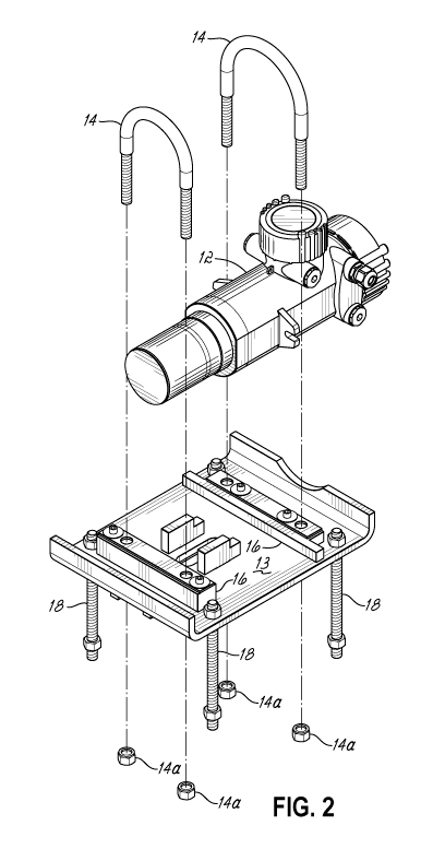
  • At the time of issue of the patent (grant).
(12) Patent Application: (11) CA 2939350
(54) English Title: MOUNT FOR HIGH VIBRATION ENVIRONMENT
(54) French Title: MONTURE POUR ENVIRONNEMENT A VIBRATIONS ELEVEES
Status: Dead
Bibliographic Data
(51) International Patent Classification (IPC):
  • F16F 15/02 (2006.01)
(72) Inventors :
  • AHLERS, SHAWN GREGORY (United States of America)
  • RIVERA, ESTHER MILAGROS DIAZ (United States of America)
  • WILLOUGHBY, CHRISTOPHER HAMILTON (United States of America)
(73) Owners :
  • VEGA AMERICAS, INC. (United States of America)
(71) Applicants :
  • VEGA AMERICAS, INC. (United States of America)
(74) Agent: MACRAE & CO.
(74) Associate agent:
(45) Issued:
(86) PCT Filing Date: 2015-02-23
(87) Open to Public Inspection: 2015-08-27
Availability of licence: N/A
(25) Language of filing: English

Patent Cooperation Treaty (PCT): Yes
(86) PCT Filing Number: PCT/US2015/017081
(87) International Publication Number: WO2015/127356
(85) National Entry: 2016-08-10

(30) Application Priority Data:
Application No. Country/Territory Date
61/943,292 United States of America 2014-02-21

Abstracts

English Abstract

A mechanically isolating mounting for use with a level sensing gauge (12) comprises damping material (22a, 22b) positioned exterior to the metal primary housing and between a primary housing of the gauge and a gauge mounting (13, 20, 20a), such that the damping material isolates the gauge mechanically from vibration and shock delivered through the gauge mounting. The gauge housing may comprise a mounting plate (13) or a metal enclosure (20, 20a) surrounding the primary housing and forming an outer housing.


French Abstract

L'invention porte sur une monture mécaniquement isolante pour l'utilisation avec une jauge de détection de niveau (12), laquelle monture comprend un matériau d'amortissement (22a, 22b) positionné à l'extérieur du boîtier primaire métallique et entre un boîtier primaire de la jauge et une monture de jauge (13, 20, 20a), de telle sorte que le matériau d'amortissement isole mécaniquement la jauge contre les vibrations et les chocs délivrés par l'intermédiaire de la monture de jauge. Le boîtier de jauge peut comprendre une plaque de montage (13) ou une enceinte métallique (20, 20a) entourant le boîtier primaire et formant un boîtier externe.

Claims

Note: Claims are shown in the official language in which they were submitted.


- 4 -
Claims:
1. A mechanically isolating mounting for use with a level sensing gauge
having a metal primary
housing, the isolating mounting comprising damping material positioned
exterior to the metal
primary housing and between the metal primary housing and a gauge mounting,
such that the
damping material isolates the gauge mechanically from vibration and shock
delivered through
the gauge mounting.
2. The mounting of claim 1 wherein the gauge housing comprises a metal
enclosure surrounding
the primary housing and forming an outer housing.
3. The mounting of claim 1 wherein the damping material comprises a damping
foam mounted
between the metal primary housing and gauge mounting.
4. The mounting of claim 1 wherein the damping material substantially
surrounds the metal
primary housing.
5. The mounting of claim 2 wherein the damping material substantially
surrounds the metal
primary housing.
6. The mounting of claim 5 wherein the damping material comprises a damping
foam mounted
between the metal primary housing and gauge mounting.

Description

Note: Descriptions are shown in the official language in which they were submitted.


CA 02939350 2016-08-10
WO 2015/127356 PCT/US2015/017081
- 1 -
MOUNT FOR HIGH VIBRATION ENVIRONMENT
RELATED APPLICATIONS
[0001] The application claims priority to U.S. Provisional Application
Serial No. 61/943,292 filed
February 21, 2014, which is incorporated herein in its entirety.
FIELD OF THE INVENTION
[0002] The present invention relates to mountings for level sensing gauges.
BACKGROUND OF THE INVENTION
[0003] Level sensing gauges are applied in many industrial environments and
are typically designed
to handle harsh process conditions and environments, including long term
chemical exposure, extreme
cold or heat and in some cases outdoor weather. Recently, however, these
devices have become of
interest for use in oil drilling and particularly fracking operations, which
generate very high mechanical
stress and vibration of a kind not experienced in even the harshest
environments for which the gauges
were designed. The failure rate of the sensitive electronics in the gauges has
proven to be unacceptably
high in these environments.
SUMMARY OF THE INVENTION
[0004] The present invention provides a novel mounting for a level sensing
gauge that provides
greater vibration and mechanical shock protection than has been afforded by
any known prior system.
Specifically, the invention in its two embodiments shields the gauge from
vibration via a heavy thick
layer of insulating foam that sits between the outer housing of the gauge and
the mounting plates that
mechanically couple to the well-connected equipment that is subjected to
mechanical shock, e.g.
mechanical shock produced for fracking.

CA 02939350 2016-08-10
WO 2015/127356 PCT/US2015/017081
- 2 -
[0005] The above and other objects and advantages of the present invention
shall be made
apparent from the accompanying drawings and the description thereof.
BRIEF DESCRIPTION OF THE DRAWINGS
[0006] The accompanying drawings, which are incorporated in and constitute
a part of this
specification, illustrate embodiments of the invention and, together with a
general description of the
invention given above, and the detailed description of the embodiments given
below, serve to explain
the principles of the invention.
[0007] Fig. 1 illustrates a first embodiment of the invention in which a
level sensing gauge is
mounted to a mounting plate by U-bolts, but is mechanically isolated from the
mounting plate by a thick
layer of damping foam sandwiched between the outer housing of the gauge and
the mounting plate.
[0008] Fig. 2 is a disassembled perspective view of this first embodiment
showing the mounting
plate, damping foam on the upper side of the mounting plate, the gauge, and
the U-bolts.
[0009] Fig. 3 is a perspective view of a second embodiment of the invention
in which a level sensing
gauge is entirely encased in a second housing surrounding the primary gauge
housing.
[0010] Fig. 4 is a disassembled perspective view of this second embodiment
showing the two parts
of the outer housing, the gauge, and the conforming damping form the
encapsulates the main housing
of the gauge and isolates the gauge mechanically from the outer housing.
[0011] Fig. 5 is a cross section along lines 5-5 of Fig. 3 showing the
encapsulation of the gauge main
housing inside of the isolating damping foam, which is itself captured within
the outer housing.
DETAILED DESCRIPTION OF THE INVENTION

CA 02939350 2016-08-10
WO 2015/127356 PCT/US2015/017081
- 3 -
[0012] Fig. 1 and Fig. 2 illustrate a level sensing gauge 12 mounted to a
mounting plate 13 by U-
bolts 14, which are held firmly to mounting plate 13 by nuts 14a (Fig. 2).
Level sensing gauge 12 is
mechanically isolated from the mounting plate 13 by a thick layer of damping
foam 14 sandwiched
between the outer housing of the gauge and the mounting plate. The mounting
plate 13 is mounted to
surrounding structure via mounting bolts 18.
[0013] Figs. 3 and 4 are perspective views of an embodiment of the
invention in which a level
sensing gauge 12 is mounted to a mounting plate 13 similar to that shown in
Figs. 1 and 2, and entirely
encased in an outer housing, comprising a body 20 and cover 20a. The outer
housing 20/20a surrounds
the primary housing of the gauge 12, thus forming a double housing. Within the
outer housing, the
gauge 13 is surrounded by conforming damping foam sections 22a and 22b which
encapsulates the
primary housing of the gauge and isolates the gauge mechanically from the
outer housing 20/20a.
[0014] Fig. 5 is a cross section along lines 5-5 of Fig. 3 showing the
encapsulation of the primary
housing of the gauge 13 inside of the isolating damping foam 22a and 22b,
which is itself captured
within the outer housing 40/40a.
[0015] While the present invention has been illustrated by a description of
various embodiments
and while these embodiments have been described in considerable detail, it is
not the intention of the
applicants to restrict or in any way limit the scope of the appended claims to
such detail. Additional
advantages and modifications will readily appear to those skilled in the art.
The invention in its broader
aspects is therefore not limited to the specific details, representative
apparatus and method, and
illustrative example shown and described. Accordingly, departures may be made
from such details
without departing from the spirit or scope of applicant's general inventive
concept.
WHAT IS CLAIMED IS:
Representative Drawing
A single figure which represents the drawing illustrating the invention.
Administrative Status

For a clearer understanding of the status of the application/patent presented on this page, the site Disclaimer , as well as the definitions for Patent , Administrative Status , Maintenance Fee  and Payment History  should be consulted.

Administrative Status

Title Date
Forecasted Issue Date Unavailable
(86) PCT Filing Date 2015-02-23
(87) PCT Publication Date 2015-08-27
(85) National Entry 2016-08-10
Dead Application 2019-02-25

Abandonment History

Abandonment Date Reason Reinstatement Date
2018-02-23 FAILURE TO PAY APPLICATION MAINTENANCE FEE

Payment History

Fee Type Anniversary Year Due Date Amount Paid Paid Date
Application Fee $400.00 2016-08-10
Maintenance Fee - Application - New Act 2 2017-02-23 $100.00 2017-01-13
Owners on Record

Note: Records showing the ownership history in alphabetical order.

Current Owners on Record
VEGA AMERICAS, INC.
Past Owners on Record
None
Past Owners that do not appear in the "Owners on Record" listing will appear in other documentation within the application.
Documents

To view selected files, please enter reCAPTCHA code :


To view images, click a link in the Document Description column. To download the documents, select one or more checkboxes in the first column and then click the "Download Selected in PDF format (Zip Archive)" or the "Download Selected as Single PDF" button.

List of published and non-published patent-specific documents on the CPD .

If you have any difficulty accessing content, you can call the Client Service Centre at 1-866-997-1936 or send them an e-mail at CIPO Client Service Centre.


Document
Description 
Date
(yyyy-mm-dd) 
Number of pages   Size of Image (KB) 
Description 2016-08-10 3 96
Representative Drawing 2016-08-10 1 35
Abstract 2016-08-10 2 74
Claims 2016-08-10 1 20
Drawings 2016-08-10 5 180
Cover Page 2016-09-12 1 42
International Search Report 2016-08-10 1 48
National Entry Request 2016-08-10 3 86
Correspondence 2016-08-22 10 334
Response to section 37 2016-11-09 2 60