Note: Descriptions are shown in the official language in which they were submitted.
CA 02939447 2016-08-11
WO 2015/122938
PCT/US2014/059010
'PATIENT HEAT EXCHANGE SYSTEM Wrrif TWO AND ONLY TWO FLUID
LOOPS
1, HELD 01 THE INVENTION
The present application relates generally to patient .hat exchange systems
with tAriffi
and only two fluid loops,
II, BACKGROUND OF THE INVENTION
Patient temperature contml systems have been introduced to prevent fever in
patients
in the near ICU due to suffering from sub-araebnoid hemorrhage or other
neurologic malady
such as stroke.. Also., such SySiMIS have been used if3 induce mild or
moderate hypothennia to
improve the outeoines of paticats suffering from such maladies as stoke,
cardiac arrest,
myocardial infarction, tramatie brain iniwy, and high iota/cranial pressure.
Exampletrt
intravascular heat exchange catheters are disclosed in U, S. Patent Nos.
6,419,643, 6,416,533,
6,409,747, 6,405,080, 6,393,320, 6,168.,304, 6,.338,727, 6,299,599, 6,290,717,
6.287õ326õ
6,165,207, 6,149,670, 6,146,411, 6,126,684, 6,306,161, 6,264,679, 6,231,594,
6,149,676,
6,149,673, 6,119,168, 589,238, 5,879,329, 5,837,003, 6,383,210, 6,379,378,
6,364,899,
6,325,818, 6,312,452, 6,261,31'2, 6,254,626, 6,251,130, 6,25 ,129, 6õ245,095,
6,238,428,
6,235,048, 6,2,31,595, 6,224,624, 6,149,677, 6,096,068, 6,042,559, all of
which are
incorporated herein by reference,
External patient temperature control. systems may be used., Such systems are
disclosed
in U.S. Patent Nos. 6,827,728, 6,818,0127 6,802,855, 6,799,063, 6,764,391,
6,69'2,518.,
6,669,715, 6,660,027, ic,,,648,905, 6,645,232, 6,620,187, 6461,379,
6,375,674., 6,1.97,045, arid
SUBSTITUTE SHEET (RULE 26)
CA 02939447 2016-08-11
WO 2015/122938
PCT/US2014/059010
6,188,930 (collectively, "the external pad patents"), 1 of which are
incinporated herein by
reference,
SUMMARY OF THE INVENTION
A heat exchange system for exchanging, heat with working fluid from an
intravascular
heat excharig,e catheter or an extemal heat exchange pad includes a 'working
fluid circuit
contipred for circulating -working fluid between a fluid cassette and the
catheter or pad. The
system also includes a refrigerant circuit configured for ciEntlating
refrigerant between a
compressor and sides of cold plates between which the eastis disposable
in example embodiments a cassette slot is defined been the cold plates for
rweiving the fluid cassetteõAi distance between the cold. plates (e.g., the
width of the slot) mu
be less than forty mils ;0.040") and may be between twenty nine mils and
thirty one rthiS
The cold plates ean be nearly square and can abut each other along left and
.right side walls. in exwnples, respmive vertically elongated cassette frame
receptacles are
located immediately inboard of the respective side walls with the slot
extending between the
sidewalk and terminating at the receptacles, and the frairle receptacles are
wider than the slot
At least one cold plate may be formed with. a serpentine passageway through
which the
refrigerant flows.
hi mother aspect, a system includes two heal transfer plates parallel to each
other and
defining a slot between them configured for receiving a working fluid cassette
through which
working fluid flows to and from an intravascular catheter in a working fluid
circuit A
refrigerant circuit supplies refrigerant to at least one of the plates to
exchange heat therewith.
The refrigerant circuit includes a compressor and is the. only fluid circuit
in themal contact
2
SUBSTITUTE SHEET (RULE 26)
CA 02939447 2016-08-11
WO 2015/122938
PCT/US2014/059010
vyithtcworking fluid circtiit other than a bloodstream of a patient in which
the catheter cm
he posoned,
aitother aspect, isurethod includes circulating refrigenmt between a
compressor and
a cold plate, and circulating working fluid between an intravascular at
exchange catheter
and a fluid cassette disposed on contact =witii the cold at to exchange heat
between tile
refrigerant and the working fluid through the cold plate.
The details of the present invention, bodi as-tils its structure and
operation, can best he
understood in reference to the accompanying drawings, in which like reference
numerals sefer
to like parts, mid in winch:
BRIEF DESCRIPTION OF THE DRAWINGS
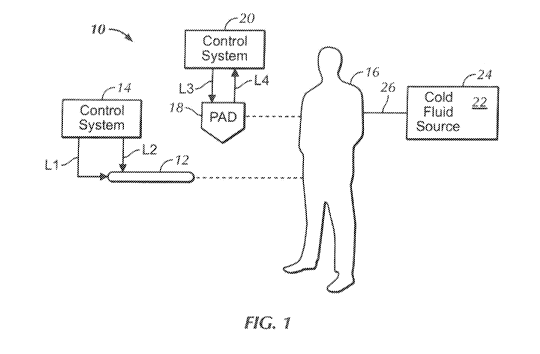
Figure 1 is a schematic view of a non-limiting system in accordance:with the
present
invention;
Figure 2 is a perspective view fano example working aid cassette holder
portion of a
heat exchange system;
Figure 3 is a perspective view of one half of the cassette holder shown in
Figaro 2,
with the opaque net inner si.irfau shownìntt-ansparency to reveal the
seipentine refligerant
passageway;
Figure 4 is a perspective view of an example working fluid cassette configured
to
engage the cassette holder shown in Figures 2 and 3;
Figure 4A is similar to Figure 4, showing the inlet and outlet tubes
extenditlg from he
top to the bottom of the membrane assembly;
3
SUBSTITUTE SHEET (RULE 26)
CA 02939447 2016-08-11
WO 2015/122938
PCT/US2014/059010
in 5 is a dose up perspective view of the cassette shown in Figure 4, amnia*
an inlet tube extending- pattially down into the stretched. .membrane chamber,
it being
understood die en opposed outlet tube may tT Similarly disposed on the
opposite aide of the
cartridge and that both the inlet and outlet tubes may extend any length down
their respective
sides in the cassette;
Figure 6 is a perspecfive view. of an alternate cassette in winch the inlet
and outlet
tubes are formed in the ham of the cassette, 1,Viih POrtiOnS broken away -14
clarity;
Figure 7 is a view in partial etoss-seetion as seen along the line 7-7 in
Figure 6, with
portions broken away for clarity, and assuming the cassette is engaged between
the cold
plates; and
Figure 8 is a schematic diagram of a refrigerant-working flahl system..
DETAILIT DESCRIPTION OF THE PREFERRED EMBODIMENT
Referring initially to Figure l, in accordance with present principles, a
system. 10 may include
an intravascular heat exchange catheter 12 controlled by a control system 14
to induce control patient
temperature, eg., to prevent the patient 16 ftoni becoming febrile or to
induce therapeutic
hypothemna in the patient .16, In the catheter, working fluid also referred to
as "coolant") such as
but not limited to saline circulates (tnically under the influence of a. pump
in the controller) in a.
closed loop from the control system 14, .through a fluid supply line LI
through the catheter 12, and
back to the system 14 throng+ a fluid return line L2, such that no coolant
enters the body. While
certain..preferred catheters are disclosed below, it is to be understood that
other catheters can be used
in accordance with present princiPles, including, without limitation, any of
the catheters disclosed
a.bove or in the Miming U.S. patents, aI incorporated herein by reference:
USPN 5,486,208,
4
SUBSTITUTE SHEET (RULE 26)
CA 02939447 2016-08-11
WO 2015/122938
PCT/US2014/059010
5,837,003, 6,1 10,168, 6,149,673, 6,149,676, 6,231,54, 6,264,679, 6,306,161,
6,235,048, 6,238,428,
6,245,095, 6,251,129, 6,251,130, 6,25.4,626, 6,261,31Z 6,312,452, 6,325,818,
6,409;747, 6,368,304,
6,338,727, 6,299;599, 6,287,326, 6,126,684, The catheter 12 may be placed in
the venous system,
in the supetiotor inferior vena
'Instead of or in addition M the catheter 12, the system 10 may include otle
or more pads 1$
that are positioned against the external skin of the patient 16 (only one pad
18 AlOWT1 f(11' clarity). The
pad 1.8 may be, without /imitation, any one i)f the pads disclosed in the
external pad patents. The
tempentatv of the pad I 8 can be controlled by a pad central syStetti 20 in
accordance with principles
set forth in the external pad patents to exchange heat with the patient 16,
including to induce
therapeutic mild or moderate hypothermia in the patient in response to the
patient presenting with,
e.g., cardiac airest, myocardial intlirction, stmke, high intnicranial
pressure, traumatic brain injury, or
other malady the effe..,cts of which can be ameliorated by hypothermia.
Thej.)ad 18 may receive
working; fluid from the system 20 through a fluid supply line L3, and return
Ivorking fluid to die
system 20 through a fluid return line 1,4. Note that in some embodiments, the
systems 14, 20 are
established in a single assembly.
To cool the patient while awaiting Cilgagentent of the catheter 12 and./or pad
18 with the
patient; cold fluid 22 in a cold fluid source 24 may be injected into the
patient and in particular into
the patient's venous system through a pathway 26: Without limitatim, the
pathway 26 may an IV line,
the source 24 may he an. 1-V bag, and the fluid 22 may be chilled saline,
e.g., saline at the freezing
point or slichtly warmer. Or, the source may be a sine, and the saline can be
injeeted dirµxtly into
the bloodstream of the patient.
Now referring to Figure 2, a portion of either of the heat exchangers in the
control systems 14.,
20 is shown which includes at least two cold plates 30, 32. defining a
cassette slot 34 haw.= them.
SUBSTITUTE SHEET (RULE 26)
CA 02939447 2016-08-11
WO 2015/122938
PCT/US2014/059010
iri one embodiment, the width "W" of the slot 34 is less than thrty mils
(ONO"), and may he between
twenty nine is attd thirty one mils (0.029"-0.031") or may have a nominal slot
width &f835". Itt
specific example the width 'W" may he thirty is. In cnher embodiments, when a
disposable heat
exchange hag with serpentine channels is used, a larger g,ap between the oold
plates may be used. e.g.,
0.060" 0.120" and more preferably 0,080" to promote pumping saline through the
bag without
excessive backpressure,
he cold plates 30,32 maybe made of metal, attd can be re..tilin.e.ar as Showt
and indeed inay
be nearly square. The cold plates 30, 32 M.ay abut each other along left and
right side as 36, with
elmigate d vertical. cassette frameteceptacles RI and R2. being located
inunediately inboard of the
respedive side as 36 and with the slot 34 extending. between the walls 36 and
tenninating at the
receptacles RI , R2 as shown. The frame .receptacies. R.I, :R2 are wider than
the slat 3.
In the example shown, re. get inlet and outlet tubes 3.8, 48 extend through at
least one of
the cold plates 32 to communicate refrigerant :from a conpressor into a
refrigerant passageway in the
cold plate. Each cold plate may have its own refrizerant inlet and outlet
tubes, or, in the embodiment
shown, only one cold plate may be formed with refrigerant inlet and outlet
tubes and Mc, other cold
plate either thermally coupled to the cold plate in which the refrigerant
flows andfor receiving
refrigerant from the other cold plate through passageway formed through one or
both of the side
walls 36.
Figure 3 shows details of all example cold plate 32 looking at the inner
surface in
transparency, it being understood that: the inner surface typically is metal
and that the .serpentine
rehigmant passage-way 42 shown in Figure 3 typically would not -be visible to
the human eye. In any
ease, the example refrigerant passageway that fluidly connects the refrigerant
inlet .38 to the
refrigerant outlet 40 may he serpentine-shaped as shown, or maybe some other
shape or pattern such
6
SUBSTITUTE SHEET (RULE 26)
CA 02939447 2016-08-11
WO 2015/122938
PCT/US2014/059010
as a heningbone pattern a wave pattern, etc. Alternatively, parallel chiinnel
passages may be used.
For instance, ten one-itieh wide channels may bc formed in parallel, thereby
achieving a 10x 10"
surface area.
Fig= 4 shows an example working rand. cassette 50 according to present
principles. The
cassette 50 is configued to fit snugly into the slot 34 and cassette .frame
receptacles RI, R. defined
between the cold plates 30, 32, Working fluid such as saline from a pan ent-
engazeahle heat exchange
member such as the catheter 1.2 or pad 18 flaws through the cassette 50 in
emation, with the working
_fluid exchanging heat with the refrigerant in the cold plates. In example
embodiments, the cassette 50
is a low cost sale-se disposable item that eau contain, e.g., sterile &ale
which eiratlates through
the catheter 12. The cassette may he placed by a medical caregiver in the slot
34 between the cold
plates 30, 32 and the membrane portion Which defines a space or working- fluid
chamber through
which the example saline flows inflates when the working fluid flows through
it, achieving thermal
contact with the cold plates 30, 32.
in the ample shown, the cassette 50 includes a frame 52 defining a periphery
and a
preferably rectilinear opening bounded as shown on at least three side by the
periphery of the frame,
hi the non-limiting example shown, the frame includes an elongated
pandielepiped-shaped top rail 53
and elongated paralielepiped-shaped left and right side rails. 54 parallel to
each other and
perpendicular to the top rail 32. The example. frame 52 has no bottom rail
opposite the top rail. hr
any case, the example frame 52 is rectilinear and is configured for being
closely received between the
.two cold plates 30, 32, with the side rails 54 .slidably engageable ,vith the
itame receptacles R I, R2
between the cold plates 30, 32 and with the below-described membrane asse,mbly
passed through the
slot 3.6 to be in close juxtaposition with the refrigerant channels in the
cold plates.
7
SUBSTITUTE SHEET (RULE 26)
CA 02939447 2016-08-11
WO 2015/122938
PCT/US2014/059010
in eross-references to Figures 4 and 5õ the frame, in the example sbown, the
top rail 53 thereof,
is formed with a fluid inlet 56 in which tm inlet tube 58 has bt.'en disposed
and a fluid outlet 60 in
which an untie tube 62 has been disposed. Both the inlet and outlet establish
respective fluid
passageways through the frame into the opening. The inlet and outlet tubes 58,
62 nmy be engaged
with the fluid return a.nd supply lines 1.3õ IA that are associated with the
catheter 12. The tubes 58, 62
may terminate at just below the top rail 53 (T.',igure 4), or they blay extend
any desired length down to
the bottom of the assembly, ie., the tubes 58, 62 may extend almost the entire
length of the left and
right side mils 54, ending just above the be-low-described bottom seam of the
membrane assembly
Figure 4A).
Indeed, a polymeric, membrane assembly 64 is connected to the frame 52,
blocking the
opening, that is bounded on three sides by the frame as shown. The membrane
assembly includes a
first ineiribrane 66 that is parallel to and closely spaced from a second
membrane 68, leaving a space
there between whieh establishes a working fluid chamber, The fluid inlet 56
and fluid outlet 60
communicate with the space between the membranes 66, 68. At least one and
preferably both of the
membranes 66, a are disposed in tension in the opening. The space between the
membranes is
expandable when filled with working fluid.
In one example,. each mein bran is no inore than two mils (0,002") thick and
inore preferably
is between one mil and two :mils in thickness (0.001"-0,002"), inclusive. The
example preferred
membranes 66., 68 are co-exterise with the opening and like the opening are
more or less square,
with the. length of top and .hotbom edges of tile example membranes being
approximately equal (within
0% mid more preferably within + 550 of the lengths of the left and right
edges of die tnembranes..
Thus, the working fluidd chamber between the membranes is also rectilinear and
in the preferred
8
SUBSTITUTE SHEET (RULE 26)
CA 02939447 2016-08-11
WO 2015/122938
PCT/US2014/059010
embodiment no obstructions exist between the membranesõ meaning the workin.g
.fluid chamber is a
complete rectilineal., more in. less square chamber,
Owing to the thinness of the menibranes 66, 68 and the closeness of the cold
plates 30,32 to
each other aM to the membrane assembly between thetn when the cassette is
engaged with the cold
plates, the system shown in the figures affords low impedance ofat transfer
hetwee.ri the .re.fri gerant
cireulating in the cold plates and. the 'werkirig fluid circtilating between
the membranes 66, 68.. The
working fluid. chamber between the membranes inflates due to backpressure
generated by working
fluid flow, eliminating o.r reducing die need for a moving mechanism in the
cold plates. Moreover,
the narrow slot 34 between the two cold plates provides better heat transfer
by reducing the
conductive path length between the cold plates and the ,õvorkin fluid. The
frame allows for ease of
handling, such as insertion and removal of the cassette with/from the wid
plates..
With respect to the example working fluid chamber between the membranes 66, 68
having a
width-to-length aspect ratio .near 1 : I (i.e., square Or nearly so), the
amount of backpressure req-uired to
induee working fluid flow through heat exchanger is reduced compared to a less
square configuration..
This :reduces the amount of work that a working fluid pump must perform, which
is desirable for two
reasons. One, since the pump may be disposable, lowc.-r performance
requirements translate into a
lower cost Chsposalade and quieter system. For instance, peristaltic roller
potorpso.tier quiet operation
mid a low-cost disposable element, but operate most efficiently when only
modest pressures are
required. Two, lowering the working fluid pump siork reduces the amount of
heat transferred into the
working fluid by the pump itself. Also: a Iow widthllength aspect ratio
results in slower working fluid
velocity which reduces aMount of mixing, but this otherwise d.esita.ble (from
a heat exchange
standpoint) effect is negligible in the prescsnt example system since the
Reynolds nunthets are
typically < 1000, suggesting a laminar flow regime. Furthermore, a low
width/length aspect ratio
9
SUBSTITUTE SHEET (RULE 26)
CA 02939447 2016-08-11
WO 2015/122938
PCT/US2014/059010
signantly reduces. the n ber c:tf bends tor "cerriers") in the fluid flow
path. These bends are. areas
of mixing for the fluid which..pnunotes heat transfer. Without them, a fluid
botin&i:y layer builds up.
However, this effect is offset herein by maintaining a narrow slot between the
cold plates. This way
the primary heat transfer meehanism is by conduction, but the conduction path
length. (and therefore
-boundary layer) is small, resulting in a relatively high rate of heat
transfer,
hi preferred examples, the membranes 66, 68 are stretched under tension during
assembly to
the flume, This tension MI be maintained over the shel f life of the product,
Pretensioning minimizes
wrinkles in maioial, which is beneficial because wrinkles carì impede working
fluid flow and create
air gaps .which reduce heat transfer- between the working fluid and cold
plates. Wrinkles, can also
complicate insertion of the membrane assembly into the narrow slot 34.
To establiSh pre -tensioning of the membranes, the frame may be made in halves
and posts
such as threaded fastenen 70 (Figure 5) can extend transversely to one half
oldie frame, with the
membranes 66, 68 being stretched over the posts and holes made in the
membranes to receive the
posts. The other half of the frame is then positioned to sandwich a
rectilinear border portion 74 Only
the innermost ixmlion of which is shown in Figure 5) of the .mernbrime
assembly between the frame
halVCS, and a closure such as respective nuts 72 engaged with the posts 70 to
hold the frame halves
together with the :membrane assembly held in tension between the .frame
halves, Figure 4 shows that
the working fluid chamber is closed off at the bottom by a bottom seam 74A of
the membrane
assembly, which is part of the border portion 74.
in the border portion 74, at least one ami preferably more lams of polymer
film :may heused
to reinforce the membranes 66, 68 to estsLIilì welded seams throngh which (at
the sides of the
membrane assembly) the post holes ane= formed, allowing for easier
fabrication. By placing
reinforcing layers on the border portion 74 only, the central "window" of the
membrane assembly
11)
SUBSTITUTE SHEET (RULE 26)
CA 02939447 2016-08-11
WO 2015/122938
PCT/US2014/059010
consists oaly of a single thin layer membrane Itetween the working fluid and
one of the cold plates
30, 32 to minimize impedine heat transferõA die-cut rei3.1forcement layer ntay
he used which
reinfbrees the entim perimeter with one piece of material.
In some examples, the polymer membranes 66, (8 are highly stretchable, at
least greater than
elongation. Tins allows the me.mlanmes to change from the empty at state shown
in Figures 4
and 5 to an inflatod shape (within the slot 34 between the cold plates)
without wainkling. lt also
allows the membranes to easily conform to features on the faces of the cold
plates.
Additionally, the illethbranes may be made of a material which can also be
iriade into tubing.
Tubes such as the inlet and outlet tubes 58, 62 shown in Figure 4 can then be
thermally welded
using RF sealing) to the membranes, which is niore reliable and quicker than
adhesive bonding. The
membranes 66, 68 need not provide their own. lateral stir:Tort because the
cold plates 32, 34 and frame
pride the support for the inflated membraae assembly, allowing it to withstand
the press=
generated as a result of-working, fluid flowitti.:,, through been the
membranes. Smtetural features
may be located an the cold plates to optimize heat transferõ This can be
economically adaaintagwus
because the cold plates are reusable components. Manifolds can be cut into the
cold-plates to even out
the distribution of saline flow.
Figures 6 and 7 show that alternatively, a working fluid inlet 80 may be
thrilled in the left mil
of a frame 82 holding a membrane assembly 84 in tension. lt is to be
understood that a working fluid
outlet may be formed in the right rail ofthe frame 82. The inlet 80 and outlet
.may extend almost the
entire lengtl ofthe nail if desired or May extend only part way down the rail.
In any case one or more
lateral channels 86 extend from the inlet 8(l to the working fluid chamber 88
of the membrane
assembly 84 to establish fluid communication between the Wet (and outlet) of
the frame 82 and. the
working fluid chamber. If desired., the cold plates 30, 32 /ray be formed with
a chamfer 90 at the start
11
SUBSTITUTE SHEET (RULE 26)
CA 02939447 2016-08-11
WO 2015/122938
PCT/US2014/059010
of the slot 92 in which the membrane assembly 84 is disposed, with a
complementarily shaped
chamfer 94 being formed in the rail of the frame 82, to accommodate any
"ballooning" of the
membrane assembly 84 at the frameimembrane interface as the saline flows out
of the frame into the
metribrane ass:embly.
Fig= 8 ShOWS an example system 100 that may use the fluid cassette 50 betwem
the cold
plates 30, 32. The spttem 100 may be FM embodiment of either system 14, 20
shown in Figure I, for
example. Refrigerant cimilates from a compressor 102 through a refrigerant
supply line 104 to at
least one of the cold plates as shown. In the embodiment shown, the
refrigerant circulates through a
cold plate bottom coupler 106 from the first cold plate 30 to the second cold
plate 32 and back to the
compressor 102 through a refrigerant return line 108. In 6ther embodiments the
refrigerant may flow
only through the first cold plate 30 which, owing to thermal coupling through
the bottom coupler 106
-with the second cold plate n, equalizes the temperahlre Elf the SeC0fid cold
plate 32 with the
temperature of the first cold plate 30. Yet again, separate refrigemnt supply
and return lines apart
from the lines 104, 108 may he provided between the compressor 102 (or iildeed
a second
compressor) and tb.e second cold plate 32.
Thus, as shown M Fimire 8 only two Ihnd loops =refligerant and working fluid --
- need be
used. The "prime mover" of the heat exchange in the system 100 is the
refrigeram loop with
compressor, and it directly exchanges heat with the end Use fluid system, the
working fluid loop.
JhJ.ethe particular PATIENT HEAT' EXCHANGE SYSTEM WITH TWO AND ONLY
TWO FLUID LOOPS is herein shown and described in detail, the scope of the
present invention is to
be, limited by nothing other than the appended claims.
12
SUBSTITUTE SHEET (RULE 26)