Note: Descriptions are shown in the official language in which they were submitted.
CA 02939676 2016-08-12
WO 2015/126320 PCT/SE2015/050197
1
Device and method for establishing a temporary connection between two movable
objects
The present invention relates to a device and a method for establishing a
temporary
connection between two objects that are movable in relation to each other,
particularly
where both objects comprise a respective connecting means, and wherein the
temporary
connection is established by the connecting means being connected to each
other.
In many situations, objects that are movable in relation to each other need to
be connect-
ed, such as various vehicles which are movable relative to each other or a
moving vehicle
-to that is movable to an installation on land which is fixed as such. It
is also common that
there is a need for such temporary connections to be established and
maintained for a
period of time during which the objects are not only movable, but are actually
moving
relative to each other.
For example, systems are previously known for automatic mooring of boats at
quays,
which systems retain the boat in question while a connection for, for example,
fresh water
supply and electricity, is established and maintained.
US 2010272517 discloses a system of this type, wherein a boat is softly
captured by a
mooring means of a quay, which is pushed out to the boat's hull and then
reduces the
speed of the boat towards the quay by pressing against the hull. The mooring
means may
comprise suction cups.
US 821 526 discloses a similar system, in which a mooring means actively
follows the
movements of the boat while the boat is being moored.
For land based vehicles, it is known, for example from U52011082612, to detect
the
position of such a vehicle, to engage with it and to bring it into a position
in which an
electrical connection can be established between the vehicle and a charging
station.
CA 02939676 2016-08-12
WO 2015/126320 PCT/SE2015/050197
2
Within the same earlier technical field it is known to use a multi-axis
robotic arm to
automatically move a connector to a vehicle and there to establish an
electrical connec-
tion.
Within the field of avionics, it is known, for example from U520100282912, to
actuate a
first movable object, in the form of an aircraft, in relation to a second
moving object, in
the form of a second aircraft, such that a connection between the objects is
established by
means of respective connecting means.
It would be desirable to provide a flexible and automatic way to make a
connection
between two objects that are movable in relation to each other, which objects
can be
allowed to move relative to each other in an at least partially unpredictable
manner while
a connection is being established and maintained.
Furthermore, in many applications for example within the field of public
transport, such as
electrically driven traffic ferries and coaches, it is desirable to transfer
as much electrical
energy as possible to a craft during a limited charging time during which the
craft exists at
a loading station. This is especially a problem because it requires
significant investments
to provide a charging system that can transmit high power electrical energy.
The corresponding problem exists, for example, for boats and ships in sea
locks, where
there is also limited time for filling and draining of water and the like.
The present invention solves the above described problems.
Hence, the invention relates to a device for providing a temporary connection
between
two objects that are movable in relation to each other, wherein the first of
said objects
comprises a first connecting means and the second of said objects comprises a
second
connecting means, whereby said temporary connection is established by the two
connect-
.. ing means being brought together and connected to each other, wherein the
device
further comprises a movable first robot, arranged to continuously displace the
first con-
3
necting means relative to the first object, and a control means, arranged to
control the
movements of the first robot and as a result the said displacement of the
first connecting
means relative to the first object, wherein the device further comprises a
sensor arranged to
continuously read the relative position between of first object or the first
connecting means
and the second connecting means while the said objects are moving relative to
each other,
which device is characterised in that the control means is arranged to, while
said first and
second objects move relative to each other, continuously control the first
robot so that the
first connecting means is displaced relative to the first object and up to the
second
connecting means, and there connects to the second connecting means so that
said
.to temporary connection is thus established.
Furthermore, the invention relates to a method for providing a temporary
connection
between two objects that are movable in relation to each other, wherein the
first of said
objects comprises a first connecting means and a second of said objects
comprises a second
connecting means, wherein said temporary connection is established by the two
connecting
means being brought together and connected to one another, wherein a control
means
continuously controls the movements of a movable first robot so that the first
connecting
means is thereby displaced relative to the first object, wherein a sensor
means continuously
reads a relative position between the first object or the first connecting
means and the
zo .. second connecting means while said objects are moving relative to each
other, which
method is characterised in that, while said first and second objects move
relative to each
other, the control means continuously controls the first robot so that the
first connecting
means is displaced relative to the first object and up to the second
connecting means, and
there connects to the second connecting means so that said temporary
connection is thus
established.
Furthermore, there is disclosed a method for providing a temporary connection
between first
and second objects that are movable in relation to each other, wherein the
first of said
CA 2939676 2020-02-12
3a
objects comprises a first connecting means and the second of said objects
comprises a
second connecting means, said temporary connection is established by the first
and second
connecting means being brought together and connected to each other, the
method
comprising measuring, with a sensor means, a relative position between the
first object or
the first connecting means and the second connecting means while the first and
second
objects move relative to each other. The method further comprises, while said
first and
second objects move relative to each other, controlling, with a control means
and based
upon a signal from the sensor means, motions of a first robot to: displace the
first connecting
means relative to the first object and up to the second connecting means, and
connect the
w first connecting means to the second connecting means so that said
temporary connection is
established. Relative movement of the first and second objects including the
first and second
objects being brought together from a first separated position to a parked
position, in the
first separated position, the first and second objects are located at a
distance from each
other that is too great to establish the temporary connection, and in the
parked position, the
.. first and second objects are located so close to each other that the first
robot can reach to
achieve said temporary connection and in which respective equilibrium
positions or centers
of motion about which the first and second objects move are immobile in
relation to each
other. The control means controls the first robot so that the temporary
connection is
established while the first and second objects are being brought together from
the first
separated position towards the parked position and before the first and second
objects have
time to reach the parked position.
In the following, the invention will be described in closer detail, partly in
connection to the
accompanying drawings, in which
Figure la illustrates a first embodiment of a device according to the
invention, from the side;
Figure lb illustrates a second embodiment of a device according to the
invention, from the
side;
Date Recue/Date Received 2021-07-29
4
Figures 2a and 2b illustrate a third embodiment of a device according to the
invention from
above and from the side, respectively;
Figures 3a-3c illustrate three different successive steps performed using a
fourth
embodiment of a device according to the invention, from above;
Figures 4a to 4g illustrate various types of connections, from the side;
Figures 5a-5c illustrate three different successive steps by a fifth
embodiment of a device
according to the invention, from above;
Figure 6 illustrates an activating means according to the invention, from the
side;
Figure 7 is a flow diagram illustrating a method according to the invention;
and
io Figure 8 illustrates a sixth embodiment of a device according to the
invention, from the side.
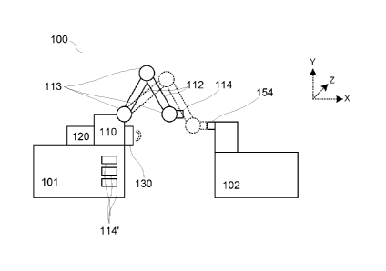
Figures la and lb show two respective diagrams of respective preferred
embodiments of
devices according to the present invention. Figures la and lb share reference
numbers for
corresponding parts.
The device 100 is thus arranged to provide a temporary connection between a
first 101 and a
second 102 object, which are movable relative to each other. The first 101 of
said objects
comprises a first connecting means 114, and the second 102 of said objects
comprises a
second connecting means 154. The said temporary connection is established by
the two
connecting means 114, 154 being brought together and connected to each other.
A connection in the sense of the invention does not only, preferably not
primarily, preferably
not at all, constitute a mooring of or between the objects, but aims at
transferring a medium
or energy from one object to the other. See below for examples.
The device 100 further comprises at least one mobile robot 110, arranged to
continuously
move the first connecting means 114 relative to the first object 101, and a
control means
Date Recue/Date Received 2021-07-29
CA 02939676 2016-08-12
WO 2015/126320 PCT/SE2015/050197
120, arranged to control the movements of the robot 110 and thus said
movements of the
first connecting means 114 relative to the first object 101.
Additionally, the device 100 comprises a sensor means 130, arranged to
continuously read
5 a relative position between the first object 101 or the first connecting
means 114 and the
second connecting means 154 while the two objects 101, 102 move relative to
each other.
According to the invention, the control means 120 is arranged to, while said
first and
second objects 101, 102 move relative to each other, continuously control the
movements
io of the robot 110 so that the first connecting means 114 is displaced, in
relation to the first
object 101 and up to the second connecting means 154, and there connects to
the second
connecting means 154, so that said temporary connection thereby is
established. Figures
la and lb both illustrate, using broken lines, the situation when the
temporary connection
has been established.
The different elements 110, 120, 130 are in communication with each other.
Thus, the first connecting means 114 is movable relative to the first object
101, via the
robot 110. In Figures la and lb, the robot 110 is illustrated with a number of
rigid seg-
ments 112 that are movable by arranged joints 113, but it will be appreciated
that other
types of robots can be used, such as traverse or crane robots, see below.
Since the sensor
means 130 is arranged to read the relative position of the second connecting
means 154
relative to the first connecting means 114, or in relation to the first object
101, and as a
result, since the robot 110 can give feedback regarding a position of the
connecting means
114 relative to the object 101, indirectly in relation to the first connecting
means 114, the
control means 120 can transmit signals to the robot 110 in order to displace
the first
connecting means 114 in a direction towards and up to the second connecting
means 154,
to a position in which the said temporary connection can be established.
In Figure lb the likewise preferred alternative is illustrated that also a
second robot 150 is
used, in combination with a control means 160 and a sensor means 170. The
robot 150,
CA 02939676 2016-08-12
WO 2015/126320 PCT/SE2015/050197
6
the control means 160, the sensor means 170, the segments 152 and the joints
153
correspond to and have the corresponding function as the robot 110, the
control means
120, the sensor means 130, the segments 112 and the joints 113, respectively.
The robot
150 is thus arranged to move the connecting means 154 relative to the object
102; the
sensor means 170 is arranged to continuously read a relative position between
the object
102 or the connecting means 154 and the connecting means 114 while the objects
101,
102 move relative to each other; and the control means 160 is arranged to
control the
movements of the robot 150 and thus the said displacement of the connecting
means 154
relative to the connecting means 114.
Thus, the robots 110, 150 cooperate in this case, in order to together cause
the connect-
ing means 114, 154 to approach each other and to assume a position relative to
each
other in which the connection can be established. The cooperation can be
achieved by the
control means 120, 160 acting independently of each other, or by the control
means 120,
160 communicating with each other, in an as such known manner, such as using
wireless
Internet, in order to coordinate the displacement operation. What is said in
the following
regarding a device with a single robot applies mutatis mutandis to a
configuration in which
two robots work together as is exemplified in figure lb.
An important aspect of the invention is that the first connecting means 114 is
moved up to
the second connecting means 154, and there connects to the second connecting
means
154, while said first and second objects 101, 102 move relative to each other.
In other
words, the objects 101, 102 are not only movable relative to each other, they
actually
move while the connecting means 114, 154 are brought together, and preferably
also
while the connection is established, either by the object 101, the object 102
or both
moving relative to a fixed coordinate system.
Such a device makes it possible for a connection to automatically be
established between
objects of different types that are movable relative to each other, which in
many such
cases can lead to significantly improved security and/or comfort for an
operator of one
101 and/or the other 102 of said objects.
CA 02939676 2016-08-12
WO 2015/126320 PCT/SE2015/050197
7
Furthermore, the use of such a device, by means of the sensor means 130, the
control
means 120 and the movable robot 110, may result in that a connection can be
established
even before the objects 101, 102 have reached a stable position relative to
each other. As
a result, a much more flexible way to establish a temporary connection between
the
objects 101, 102 is achieved, which flexibility in turn can be used to
increase the efficiency
of transmitting a medium between the objects 101, 102.
Such efficiency gains and other advantages will be more fully understood by
the subse-
quent part of the description, in which the invention will be made further
concrete by
means of a number of exemplary embodiments.
As regards the guide means 120, it may be of any suitable type, and preferably
comprises
a microprocessor, a digital memory, at least one input for measurement data or
position
.. data and at least one output for controlling the movements of a robot. A
control software
is arranged to be executed on the control means hardware and thus to perform
the said
control as such, based on a number of predefined rules and patterns. The
control device is
in contact, for digital communication of information, with other parts of the
device 100,
such as with the sensor means 130 and the robot 110.
The sensor means 130, which is arranged to sense the position of the
connecting means
154 in relation to the object 101, may likewise be of different types.
Preferred sensor
means include such sensor means that operate without contacting the connecting
means
154, such as optical sensor means, comprising one or more cameras in
combination with
an image analysis software arranged to identify certain previously known
visual markers
on the connecting means 154, such as text indicating the identity of a craft,
such as the
IMO number (International Maritime Organization) of a vessel, or known
structures that
are located at known positions relative to the connecting means 154; laser
based or
ultrasonic based detection means, arranged to scan a surface comprising the
connecting
means and/or to identify a structure of the surface and/or a distance to such
a surface; an
CA 02939676 2016-08-12
WO 2015/126320 PCT/SE2015/050197
8
infrared camera; or the like. Radar technology, long-range RFID or the like
can be used to
identify an approaching object, which can thereafter for example be identified
visually.
It is preferred that the sensor means operates in two stages, the first stage
involving the
detection, and preferably also identification, of an approaching vehicle. This
may be
performed using radar, AIS, long-range RFID or by other means, above. The
second step
involves visually identifying the location of the vessel, and especially the
position of one or
more connecting means on the vessel.
io Examples of suitable means for such visual identification include an
industrial camera,
preferably for detecting infrared light alternatively equipped with its own
light source such
as a laser light source, such as the camera IPR438ESX commercially available
from the
company Meritilin, Taiwan. Such a camera may for example be used together with
a piece
of software such as that commercially provided by Tordivel AS, Norway, under
the trade
name Scorpion Vision.
It is preferred that the objects 101, 102 are movable relative to each other,
and also that
they move relative to each other during the said movement of the means 114
relative to
the means 154, along at least two dimensions of motion, such as across a
surface, prefer-
ably along at least three dimensions of motion X, Y, Z, such as in a space. As
to the control
means 120, it is preferably arranged to control the movement by the robot 110
of the
means 114 along at least two, preferably three, dimensions of motion X, Y, Z,
and most
preferably at least along as many dimensions as the number of dimensions along
which
the objects 101, 102 move relative to each other during said movement. This
also applies
to the number of operating dimensions along which the robot can displace the
connecting
means 114.
Figures 2a, from the top, and 2b, from the side, illustrate an exemplary
embodiment of
the invention in which one 201 of the two objects is fixedly arranged and
comprises a
robot 210, while the other object 202 is movable relative to the first object.
In the present
example, one 201 of the objects is permanently installed on a quay 203, and
the other
CA 02939676 2016-08-12
WO 2015/126320 PCT/SE2015/050197
9
object 202 is permanently installed on a boat 204 or a vessel that floats on a
water surface
next to the quay. It is preferred that the connection that is established in
accordance with
the above described is a connection with the purpose of delivering, between
the objects
201, 202, electrical energy, fresh or waste water and/or powder, gaseous or
liquid sup-
plies such as methane gas, and food. For example, the electrical energy may be
supplied
to the vessel 204 via an electrical connection and electrical cables; fresh
water may be
supplied to the boat 204 via a pressurized water supply and water pipes; waste
water may
be removed from the vessel 204 via a connection which comprises an opening in
which a
hose is inserted into and sucks the waste water out from the vessel 204; or
supplies may
io be delivered to the boat 204 via a corresponding connection, but wherein
the hose which
is inserted into the opening is arranged to deliver such supplies into the
boat 204.
The first object 201 can also be fixedly mounted on a floating pier, or on a
service boat. In
these cases, hence, both objects 201, 202 are movable relative to each other
and to the
fixed coordinate system (X, Y, Z). In all these cases, the connection may be
established
despite the fact that, and while, the objects 201, 202 move relative to each
other, which
facilitates efficient delivery of the above types of substances at piers and
in harbours.
The connecting means 214 and 254, as well as the control means 220 and the
sensor
means 230, are similar to the above-described parts 114, 254, 120 and 130, as
is the fixed
coordinate system (X, Y, Z).
For example, when the device 200 is installed for use at a quay, but also in
other embodi-
ments, when the position of the second object can vary over a relatively broad
area in
relation to the first object at the time of a desired connection between the
objects, it is
preferred that at least one of the robots is fixedly mounted on a coarse
adjustment device,
by means of which the robot 210 and/or the first connecting means 214 is
displaceable in
at least one direction, preferably at least two directions, relative to the
first object 201.
The controller 220 is then arranged to control the position of the coarse
adjustment
device relative to the second object 202, and also to control the movements of
the robot
CA 02939676 2016-08-12
WO 2015/126320 PCT/SE2015/050197
210, relative to the coarse adjustment device, to thus fine tune the position
of the first
connecting means 214 relative to the second connecting means 254.
Such a coarse adjustment device enables the device 200 to be quickly adapted
to the
5 general position for the establishment of the connection, and can
thereafter establish the
connection with high efficiency and accuracy once the coarse adjustment is
completed. It
is also preferred that the fine tuning with the help of the robot 210 is
commenced before
the coarse adjustment is completed, so that the fine-tuning can be completed
with satis-
factory precision only a short time after the coarse adjustment is completed.
This is
io preferably done by the control means 220 using existing information
regarding the final
position for the coarse adjustment as a basis for an approximate calculation
in advance of
the movements called upon by the fine-tuning.
The coarse adjustment device preferably comprises a linear path 215a along
which a
carriage 215b carrying the robot 210 can be brought, by means of electric
motors and as
controlled by the control means 220, in figures 2a and 2b along the Y
direction.
In a particularly preferred embodiment, also illustrated for exemplary
purposes in figures
2a and 2b, the first object 201 is fixedly installed adjacent a boat or ship
sea-lock, where
the water surface level is variable (Z direction). In this case, preferably
the fixed system
object 201 further comprises a height adjustment means on which the robot 210
is
mounted. The height adjustment means comprises preferably a platform 215f,
supported
by an electrically driven hoist means 215e, which is controlled by the control
means 220,
and which in turn is supported by a carriage 215b of the said coarse
adjustment device.
The platform 215f then carries the robot 210, which in turn is used for the
fine-tuning.
In the illustrated example, the coarse adjustment device further comprises a
carriage
215d, which rests on the carriage 215b and is supported by an electrically
driven linear
displacement device 215c by which the carriage 215d may be linearly displaced
relative to
the carriage 215b in the X direction, under control of the control means 220.
CA 02939676 2016-08-12
WO 2015/126320 PCT/SE2015/050197
11
In other words, the robot 210 is itself displaceable in three perpendicular,
or substantially
perpendicular, directions, in the illustrated example the X-, Y- and Z-
directions. It is also
possible for the paths 215a, 215c and the hoist 215e to follow respective
curvilinear paths,
depending on the geometric conditions at the quay 203 or the location where
the connec-
tion is to be established.
It is further preferred, in the said example with a sea-lock, that the control
means 220 is
arranged to continuously control the position of the robot 210 in the vertical
direction (Z-
direction), by controlling the said height adjustment means to correspond to
the actual
io .. level of the water surface. This control is preferably conducted during
the above-
mentioned coarse adjustment phase.
It is particularly preferred that the control means 220 is arranged to, in a
first step, control
the height adjustment means to a position vertically corresponding to the
current level of
the water surface, and in a second step to control the height adjustment means
to main-
tain the controlled height position, irrespective of any ongoing water surface
level chang-
es, while the connection is being established and maintained. This may mean
for example
that a ship arrives at the robot 210, which is then coarsely adjusted to the
correct position
in the Y direction, to correspond to a current position of the connecting
means 254, as
well as in the Z-direction, depending on the current water surface level.
While the connec-
tion is being established, and also thereafter, the water level rises or
sinks, as a result of
the normal operation of the sea-lock, whereby the Z-position of the robot 210
is continu-
ously coarsely adjusted to substantially correspond to the water surface level
in each
moment. This means that the connection can be established and maintained
regardless of
the current operating status of the sea-lock, providing better opportunities
for planning
and efficiency of maintenance and service of boats and ships passing through
and being
present at the sea-lock.
In figures 2a and 2b, the local action radius 216a of the robot 210 is
illustrated in the
.. current, coarsely aligned, position of the robot 210. Also illustrated is
the robot's 210
global action radius 216b, when also taking into account the possibility of
coarse adjust-
CA 02939676 2016-08-12
WO 2015/126320 PCT/SE2015/050197
12
ment of the robot 210. It is noted that the coarse adjustment device extends
the total
action radius of the robot 210.
As mentioned, in figures 2a and 2b, the object 202 is fixedly installed on a
boat 204, which
boat 204 can be seen as a vehicle which is movable on a surface (the water
surface). In
this case, the surface itself is movable, in that the water level varies as a
result of waves,
tide, sea-lock activity and so on. The situation is different on land, where
the ground forms
a solid surface, and wherein the vessel is a land-based vehicle such as a car,
a bus, a truck,
a train or the like.
When one of the objects is permanently installed on the vehicle, it is
preferable that the
second object is a permanently installed station for, through the connection
that is estab-
lished between the objects and between the objects, supplying electrical
energy, fresh or
waste water and/or supplies, or for collecting and removing exhaust gases from
an ex-
ha ust outlet of the vehicle in question. The latter is for example useful in
parking garages,
workshops and the like, where a connecting means in the form of an exhaust
pipe of an
arriving vehicle automatically can be connected by means of a robot, to a
corresponding
connecting means in the form of a suction muff for extraction of exhaust fumes
from the
exhaust pipe for disposal. In this case, the robot which controls the position
of the suction
muff relative to the position of the exhaust pipe can for example be arranged
suspended
in a coarse adjustment device comprising a linear displacement path which runs
along the
ceiling along a roadway in the garage or workshop.
As mentioned above, in alternative embodiments, the two objects can both be
installed
on respective vehicles such as floating bridges, boats or ships, floating on a
common water
surface. As an alternative to this, one of the objects can be permanently
installed on the
ground or on a building while the other object is installed on a flying craft,
or both objects
may be installed on respective flying crafts. When the connection is
established in these
cases, the said respective flying craft is in a respective flying state, and
thus above the
ground, and the connection is a connection between the objects to deliver
electrical
energy, fresh or waste water and/or supplies. In a particularly preferred
embodiment, one
CA 02939676 2016-08-12
WO 2015/126320 PCT/SE2015/050197
13
of the objects is an electrically powered aerial vehicle, such as a so-called
drone, such as
an unmanned helicopter, the battery of which is charged by electrical power
supplied
through the connection from a charging station installed on the ground, on a
building or
on a flying vessel carrying a charging station. For example, such drones may
be used to
.. distribute water for firefighting, or different pesticides agents,
fertilizers and so on as used
in agriculture.
Figures 3a-3c illustrate a particularly preferred embodiment, in which the
objects 301, 302
can assume a parked position (figure 3c) relative to each other, in which the
objects are
io arranged so closely spaced that the robot can maintain the connection,
and wherein the
objects may also assume a different, separate position (figure 3a), in which
the objects are
at a distance from one another, preferably at such a distance that it is not
possible to
establish the connection because the incoming object's connecting means is
beyond the
reach of the robot connecting means. It is preferred that at least one of the
objects in the
.. parked position moves about a respective equilibrium position or a centre
of motion
relative to the other object, and that such equilibrium positions or centres
of motion are
fixed relative to each other or to the position of the second object in the
parked position.
Examples of equilibrium positions or centres of motion include when a vessel,
which is
moored using mooring lines, moves within its limited room for manoeuvre next
to the
immobile quay; when a helicopter hovers above a charging station arranged on
solid
ground; and when two boats are moored one to the other and move within the
limited
relative room for manoeuvre allowed by the mooring.
In a first example of such a configuration, a service boat with a connection
robot according
.. to the invention, approaches and moors to a vessel comprising a fixedly
mounted connect-
ing means for supplying fresh water. In this case, the parked position is
constituted by the
boat being stably moored at the ship, but where both the service boat and the
ship moves
around a respective centre of motion, which centres of motion are immobile in
relation to
each other. The separated state is constituted by the service boat not yet
having reached
the ship, but is located at a distance therefrom.
CA 02939676 2016-08-12
WO 2015/126320 PCT/SE2015/050197
14
In a second such example, a car arrives at a repair shop, and is connected to
an exhaust
fume collecting connecting means mounted on a robot according to the above,
whereby
the car, after the entrance into the workshop, is stationarily parked above a
working pit.
The parked position is thereby reached when the car reaches an immobile
position above
said working pit, whereby both objects therefore are immobile relative to each
other, and
the separated position is constituted by that the car not yet having come to a
standstill
above the working pit, but is arranged at a distance therefrom.
The third example is when a boat or a ship arrives at a quay at which it is to
be moored or
io lie quietly otherwise, and where a connection is established between the
boat or ship and
a permanently installed device on the quay. In such case, the parked position
is constitut-
ed by the boat or ship lying still beside the quay, whereby the boat or ship,
therefore,
revolves around a centre of motion which is immobile relative to the fixedly
installed
robot on the quay. The separated state, finally, is constituted by the boat or
ship being at
.. a distance from this parked position.
Figures 3a-3c illustrate a device 300 according to the said third example,
wherein an
object 302 according to the invention is fixedly mounted on an electrically
propelled
vehicle ferry 304. The object comprises a connecting means 354 arranged to
supply
electrical current through the connecting means 354 to a battery arranged to
provide the
propulsion means of the ferry with energy for forward operation. The object
further
comprises a wireless communication means 371 for wireless communication with a
corresponding wireless communication means 321 disposed by the quay 303 and as
part
of the second object 301. The communication means 371, 321 are conventional as
such,
and may for example be a Bluetooth connection; means in themselves not
primarily
intended for mutual communication but rather for identification, such as an
RFID connec-
tion or the like; an acoustic connection or a wireless internet connection.
380 indicates a
wireless network or a wireless communication link through which communication
can take
place, such as the Internet.
CA 02939676 2016-08-12
WO 2015/126320 PCT/SE2015/050197
The object 301 further comprises a permanently installed robot 310, a sensing
means 330
and a control means 320; and the quay 303 comprises a resilient shock absorber
305 or
the like, against which the ferry is pressed in order to lie still in the
parked position. The
directions X and Y are the same as in the other figures.
5
The objects 301, 302 are thus arranged to be brought from said separated
position to said
parked position. The control means 320 is further arranged to control the
robot 310 so
that the connection is established while the objects 301, 302 move from the
separated
position towards the parked position, and before they reach the parked
position.
Figure 3a illustrates such a separated position, in which the ferry 304, which
for example is
heading towards the quay 305 to drop off and take up new vehicles for
transport across a
watercourse, is located so that the connecting means 354 is out of the robot's
310 reach
316a for contact with the connecting means 314. Figure 3b illustrates the
situation at the
time of establishment of the connection. The ferry 304, and thus the object
302, has not
yet arrived at its parked position adjacent the quay 303, where vehicles can
be dropped
off and taken up, but is in such a position that the connecting means 314 just
reaches the
connecting means 354 so that connection is possible when the robot 310 is
displaced to
an extreme position.
By thus utilizing the robot's 310 freedom of movement in combination with the
sensing of
the sensor means 330 and the logic of the control means 320, an electric
connection can
be accomplished earlier than had been possible with prior art technology. This
difference
is in many cases essential. When it comes to an electric vehicle ferry, for
example, the last
metres of travel before the ferry arrives at the quay may take tens of
seconds, while the
total charging time ashore may involve less than 10 minutes. The additional
charging time
achieved by the invention thus represents a significant share of the total
charge time.
Correspondingly, it is further preferred that the control means 320 is
arranged to control
the robot 310 so that the connection is broken during the movement of the
objects 301,
302 from the parked position and, after the objects 301, 302 have left the
parked position,
CA 02939676 2016-08-12
WO 2015/126320 PCT/SE2015/050197
16
to a second separated position, said second separated position being similar
to that
described above and wherein the objects 301, 302 again are located at a
distance from
each other.
This can be done in several different ways, as illustrated in figures 4a-4d,
all of which, with
common reference numerals, illustrate an arm or a segment 412 of a robot 410
of an
object 401, which robot 410 controls the position of a connecting means 414
arranged to,
together with a connecting means 454 arranged on another object 402 which is
movable
relative to the first object 401 even after the connection has been
established, establish
io the temporary connection. The connector 414 is supported by a supporting
part 416 of
the robot 410, and the connecting means 454 is supported by a supporting part
456 of the
object 450.
Figure 4a illustrates the case that, after the connection is established, the
connecting
means 414 is maintained at the connecting means 454 by means of a locally
arranged
fastening means 454a, which for instance, depending on the connection type,
can be
constituted by cooperating snap-lock means or magnetic means on the respective
objects
414, 454. In this position, the control means (not shown) will not actively
control the
movements of the robot 410, instead the movements R2 of the connecting means
414 will
passively follow the movements R1 of the connecting means 454. Once the
connection is
to be broken, the object 401 and/or the object 402 causes the engagement of
the attach-
ment means 454a to be released, whereby the connecting means 414 may be
brought out
from the connection and away from the connecting means 454. For many types of
con-
nections, this is a simple and therefore preferred way.
In an alternative embodiment, the control means is instead arranged to
actively and
continuously control the movements of the robot 410 so that the part 416 of
the robot
410 which is arranged to manoeuvre or maintain the connecting means 414 is
stationary
relative to the connecting means 454.
CA 02939676 2016-08-12
WO 2015/126320 PCT/SE2015/050197
17
A first example of this is illustrated in Figure 4b, in which the control
means is arranged to
actively and continuously control the robot 410 so that the connecting means
414 is
stationary, while the connection is maintained relative to the connecting
means 454. In
other words, the movements R2 of the object 414 will actively follow the
movements R1
.. of the object 454. When the connection is to be broken, the control means
may cause the
part 416 to simply bring the connecting means 414 away from the connecting
means 454.
In this case, no fastening means is required, although it is possible to
combine the embod-
iment of figure 4a with that of figure 4b. It is preferable that the robot
maintains a certain
pressure between the connecting means 414, 454.
A second example of this is illustrated in figure 4c, wherein the part 416 is
arranged to
release the connecting means 414 after the connection has been established,
and wherein
the control means then actively and continuously controls the movements of the
robot
410 so that the movements R2 of the part 416 follow the movements R1 of the
connecting
.. means 454 relatively closely, such as at most 0.2 meters away. The actual
connection is
secured with a cable 414a or the like, which runs from the connecting means
414 and to
the object 401, and through which electricity, fresh water or the like can be
supplied.
Once the connection is to be broken, the control means may control the
position of the
part 416 relative to the means 454 so that the part 416 can be re-engaged with
the means
.. 414 and then bring the latter out from the connection and away from the
means 454. It
will then be possible to break the connection at short notice and in a
controlled manner,
since the part 416 can always be kept closely to, and synchronized with
respect to speed
with, the means 414.
Thus, the robot 410 is in this case arranged to, after the connection has been
established,
free itself from the connecting means 414 so that the connecting means 414 is
then freely
movable, not counting said active control, within at least a limited area or
volume relative
to the robot 410.
Another embodiment that also involves such freedom of movement is illustrated
in figure
4d, wherein the control means is not actively controlling the position of the
part 416 or
CA 02939676 2016-08-12
WO 2015/126320 PCT/SE2015/050197
18
means 414, but the movements R1 of the body 454 are allowed to be independent,
or at
least independent within a limited volume, by the movements of the robot 410.
Instead,
the part 416 has released the means 414, in a manner corresponding to that
described
above in connection to figure 4c, and a flexible fastening means 414b,
preferably corn-
prised in the robot 410, connects the robot 410 to the connecting means 414.
The connec-
tion is secured, as is the case in figure 4c, by means of a cable 414a or the
like. When the
connection is to be broken, this is then done by way of the fastening means
414b being
arranged to, using a pulling force, break the connection when the connected
objects 401,
402 move from each other, by being arranged to be stretched and then pulling
the means
414, 454 apart. It is preferred that a collecting means, for example
comprising a reel 414c,
is arranged to capture the means 414 and to return it into appropriate
engagement with
the part 416 in order to establish a subsequent connection. As illustrated in
figure 4e, it is
also preferred that the control means is arranged to, before the breaking of
the connec-
tion, control the robot 410 to manoeuvre the connecting means 414 into a
position in
which the angle A between the stretched fastening means 414b and a pulling
apart
direction of the connecting means 414 out of engagement with the connecting
means 454
at the time of the said break falls within a predetermined range within which
damages are
not risked for any of the connecting means 414, 454 as a result of said
applied pulling
force and said pulling apart.
Figures 4g and 4f show, in sequence, another preferred option, wherein the
control means
first (figure 4f) is arranged to bring the means 416 into a position in the
vicinity of the
object 450, and within reach of a capturing or receiving means 457 of the
object 450,
which means 457 is arranged to engage with the connecting means 414 and to
bring this
up to and into engagement with the connecting means 454. Hereby, the means 414
is first
loosened from the means 416, by the means 416 or the means 457. Thereafter,
the
control means preferably actively controls the movements R2 of the means 414
so that
the means 414 is held stationary relative to the means 457. Alternatively, a
control means
of the object 450 controls a gripping means 457a of the means 457 so that it
is advanced
to and is brought into engagement with the means 414, which thus results in a
controlled
movement of the gripping means 457a relative to the object 450.
CA 02939676 2016-08-12
WO 2015/126320 PCT/SE2015/050197
19
Then (figure 4g), the means 457 brings the first connecting means 414 up to
and into
engagement with the second connecting means 454, so that the connection is
thus
established. Once the connection is to be broken, this can occur in any of the
ways de-
scribed above.
Thus, in this embodiment it is the first robot 110 that controls and/or hands
over the
connecting means 114 to the second robot 150, see figure lb. The second robot
150 then
connects the connecting means 114, 154. Thus, for example, a custom robot
installed on a
io vehicle can by itself handle complicated connection procedures
comprising doors or the
like. Moreover, the overall working range across which the connection may be
maintained
is extended, and the first robot 110 may assist in handling the wiring/tubing
when the
distance between the robots 110, 150 becomes large.
Figures la-lb and 3a-3c illustrate a respective robot 110, 310 fixedly mounted
on a
support, which robot comprises at least two, preferably at least three parts,
the relative
angles of which can be controlled. An example of a type of robot that is
useful for this and
other types of applications of the present invention is the one sold by ABB
under the trade
name IRB 2600.
Figures 2a-2b illustrate, on the other hand, a robot 210 which includes at
least two,
preferably at least three parts, which are displaceable relative to each
other. Such a robot
preferably also includes, in addition to the displaceable sections, at least
one, preferably
at least two, preferably at least three, parts, the relative angles of which
can be controlled.
Examples of suitable robots with movable parts include the one sold under the
trade
name IRB 6620LX.
In general, it is preferred that the robots described herein have several axes
and are servo
controlled, and are preferably also of standard type.
CA 02939676 2016-08-12
WO 2015/126320 PCT/SE2015/050197
These exemplifying robots can also advantageously be used in modified form,
such as an
IRB 2600 mounted on a pair of traverse cranes and a hoist, as illustrated in
figures 2a-2b,
or an IRB 6620LX with extended arm beams and supplemented with several
gripping
means and tools for different types of connecting means.
5
In general, it is preferable to use linear traverses similar to the device
215e when larger
vessels moor at the quay with the long side towards the quay, while robots
mounted
permanently on the quay can advantageously be used when smaller boats moor
with the
bow or stern to the quay.
Figures 5a-c illustrate, for exemplifying purposes, a further preferred
embodiment, in
which an electrically propelled bus 504, on which an object 502 of the type
described
above is permanently installed, travelling along a bus route passes another
object of the
type described above in the form of a bus stop 501 equipped with a charging
station for a
battery arranged in the bus 504. The bus stop 501 is further equipped with two
cooperat-
ing robots 510 and 510', which themselves, and also their position along with
respective
rails 515a, 515b, are controlled by a control means (not shown) similar to the
above
described control means. The robots 510, 510 are provided with respective
parts 516,
516' for engaging with and supporting a connecting means 514 intended to
connect an
electric cable 514d to a connecting means 554 on the bus for the transfer of
electrical
energy to the bus 504 battery while the bus 504 is present at or near the stop
501. The
cable 514d is held taut by a per se conventional stretching means 514e.
A device 500 such as the one illustrated in figures 5a-5b comprises at least
two movable
robots 510, 511', both of which in a preferred embodiment are arranged to
cooperate
with each other, so that one of them is arranged to establish said connection
and then to
free itself from the connecting means 514, while another one is arranged to
subsequently
break the connection, preferably by again grabbing hold of the connecting
means 514 and
bringing it away from the means 554.
CA 02939676 2016-08-12
WO 2015/126320 PCT/SE2015/050197
21
When the connecting means 554 of the object thus comes within reach of the
robot 510
(figure 5a), the robot 510 brings the connecting means 514 forward, in a
manner corre-
sponding to that described above, up to the connecting means 554, and there
establishes
the connection, whereby the charging commences. The connection is preferably
estab-
lished, as above, before the bus 504, and thus the object 502, finally have
arrived at a
parked position adjacent the stop 501, for instance when the bus is about to
swing in
towards the bus stop but is within reach of the robot 510.
Thereafter, the robot 510 releases the engagement with the connecting means
514, which
io is thereafter supported by the engagement with the connecting means 554
while the bus
is moving forward towards a parked position (figure 5b) adjacent to the bus
stop 501.
Meanwhile, the battery of the bus 504 is charged via the cable 514d.
When the bus 504 is again about to leave the bus stop 501 (figure 5c), the
robot 510'
brings the part 516' forward to the connecting means 514 and engages with the
same,
breaks the engagement between the means 514 and means 554 and removes the
means
514 from the means 554. This preferably occurs after the bus 504, and thus the
object
502, has left its parked position at the bus stop 501 and is on its way out
from the bus stop
501, but while the connecting means 554 is still within reach of the robot
510'.
The robot 510' can then, for example, switch places with the robot 510, by the
robots 510,
510' sliding along the rails 515a, 515b, after which the robot 510' is
prepared to establish a
connection with a next bus whose batteries must be recharged.
It is understood that a similar system 500 also can be installed, for example,
at a red light
in a traffic intersection, so that electric vehicles can be connected and
charged during the
time they arrive, wait for a green light, and re-start driving. By means of
the invention,
vehicles in this type of situation are as a result provided with maximum
charging time
even during short stoppages.
CA 02939676 2016-08-12
WO 2015/126320 PCT/SE2015/050197
22
One of the robots 510, 510' may also, as an alternative, establish the
connection in a first
position along the rails 515a, 515b, then follow the connecting means 554,
again along the
rails 515a, 515b, when the bus 504 moves forward along the bus stop 501, and
then break
the connection at a different position along the rails 515a, 515b. This also
means that the
connection can be maintained during a maximally prolonged time.
Instead of rails 515a, 515b, for example a traverse crane or a cable transport
system can
be used.
io Another embodiment in which a wheeled vessel, which is movable on the
ground, is to be
connected to an object that is likewise located on the ground, is that the
first object is a so
called terminal tractor or other towing vehicle, and the second object is a
trailer or the
like. Terminal tractors are used to quickly and efficiently move trailers in
harbours, termi-
nals, transshipment terminals and so on. In this case, a robot is permanently
mounted on
such a terminal tractor, and arranged, in a manner similar to that described
above, to
connect and possibly also release the terminal tractor to and from a trailer
to be moved.
This therefore includes managing connecting means and tubing for a pneumatic
brake
system, as well as the connecting means and cabling for electrical systems
such as braking
systems, brake lights, tail lights, turn signals, etc. Using such a system,
the connection of
the terminal tractor to trailers can be made quickly and with good safety. In
connection to
the connection itself, such a system may also be arranged to, via said
connection, auto-
matically verify the equipment, such as the condition of the brake system.
When the driver thus drives/backs the terminal tractor to the trailer in
question, the said
robot is arranged to automatically locate connecting means on the trailer, and
then to
automatically connect hoses, cables and so on to such connecting means even
before the
tractor and trailer have been connected via the so-called "fifth wheel", that
is the coupling
or coupling disc used to connect the towing vehicle to trailer.
According to a preferred embodiment, the above described sensor means
comprises a
camera, which in collaboration with image processing software is arranged to
be able to
CA 02939676 2016-08-12
WO 2015/126320 PCT/SE2015/050197
23
recognize which type the connecting means, that the connecting means of the
robot is to
connect to, belongs to, which type is identified from a number of possible
ones for which
identifying information is stored, for example, in a database of the sensor
means. Identifi-
cation of the said type takes place by identification of visual
characteristics such as the
shape of the connecting means in question or predetermined visual markers such
as two-
dimensional patterns, alphanumeric characters, and so on.
In this case, it is preferred that the device includes a selecting means
arranged to, based
on the identified connection type of the connecting means in question, choose
one of
io several possible connecting means and use this as the connecting means
which is ad-
vanced by the robot to the identified connecting means in order to there
establish the said
connection.
In this case, therefore, the object to which the robot is to connect comprises
a set of at
least two different connecting means, preferably of standard type, and the
robot compris-
es one or more gripping means arranged to locate and engage with a selectable
one of
said plurality of connecting means.
This is illustrated schematically in figure la, wherein three different
alternative types of
connecting means 114, apart from the connecting means 114, are arranged within
reach
of the robot 110 so that the robot 110 may pick up a connecting means 114,
114' which is
of a type corresponding to the connecting means 154, depending on the type of
the latter,
as detected by the sensor means 130. It is preferred that the robot also
comprises a visual
sensor means near the connecting means 114, which follows the movements of the
connecting means 114 and thus can be brought into a position near the
connecting means
154 to facilitate the identification of the type of the said connecting means
154.
Figure 6 illustrates a further preferred embodiment, wherein a robot 610
comprises a
segment 612, a connecting means holding part 616 and a connecting means 614,
while an
approaching object 602 comprises a connecting means holding part 656 and a
connecting
means 654. Apart from the connecting means 614, the robot 610 in this case
comprises an
CA 02939676 2016-08-12
WO 2015/126320 PCT/SE2015/050197
24
activating means 617, arranged to activate the connecting means 654, for
example by
using a suction cup 617a to open a door 657 which covers the connecting means
654. The
control means is arranged to control the robot 610 to, in a first step, using
the activating
means 617, activate the connecting means 654, and, in a second step, to
establish the
connection between the means 614, 654. When the connection is subsequently
broken, it
is preferable that the activating means 617 again deactivates the connecting
means 657,
for instance by the activating means 617 holding the door 657 open while the
connection
is maintained, and thereafter closes the door 657 or allows it to be closed.
io Such activating means 617 can be designed in many different ways,
depending on the type
or types of connecting means 654 to be handled by the system according to the
invention.
For example, a lid may be screwed off, unlocked, or opened, or made available
in other
ways, such as using a push button or using digitally transmitted instructions
given over a
communication link, such as the link 380.
In a particularly preferred embodiment, the device of the invention is
arranged to estab-
lish the above-described connection only in case that the amplitude and/or
frequency of
the relative movements of the objects in relation to each other during a
certain period of
time fall within an acceptable, predefined respective range. In other words,
the control
means 120 is arranged to control the robot 110 so that it establishes the
connection not
before the objects 101, 102 are sufficiently stationary in relation to each
other for a
sufficiently long contiguous period of time.
At the same time, the controller 120 is also arranged to, even before this
condition is met,
actively and continuously control the movements of the robot 110 so that the
connecting
means 114 is stationary or substantially stationary relative to the connecting
means 154.
This leads to that an effective balance can be achieved between the desire for
long total
connection time and, on the other hand, the requirement for safety for
connections that
are to be established, for example in severe weather at sea, so that a minimum
level of
safety can be guaranteed. It is furthermore preferred that the control means
120 is
arranged to break the connection prematurely in case the amplitude and/or
frequency of
CA 02939676 2016-08-12
WO 2015/126320 PCT/SE2015/050197
the relative movement of the objects 101, 102 exceed predetermined respective
values
while the connection is maintained, or if the objects 101, 102 for some reason
move apart
further than a predetermined distance, or if the connecting means 154 is
displaced out-
side of a predetermined safety zone around the object 101, or following
specific instruc-
5 tions manually given to the device 100 by operating personnel.
It is also preferred that the information regarding the approaching object
102, such as
total weight, current course, acceleration and the like are made available to
the control
means 120, for example via a communication link such as link 380, and that the
control
io means uses such data to calculate, in advance, an appropriate timing for
establishing the
connection while maintaining safety.
In this case, the system takes into account the movements of the object as
measured by
the sensor means 130, and for example the calculated inertia, and the
precision and
15 flexibility of the robot, across different parts of its working range,
as known ahead of time.
Such estimates may for example be constituted by the connection not being
established
when the approaching object 102 is moving too quickly when the robot is
operating in a
mode in which the sensitivity to shocks is greater than a certain threshold,
which in turn
depends on the said speed.
The parameters that can be considered when possible connection timings are
pondered
will typically vary depending on several factors. For example, relatively
larger safety
marginals, in terms of speed or position uncertainty, may be required for
connection in
case multiple operations are to be performed simultaneously or in sequence,
such as
opening a door and then connecting the connecting means. Additionally,
information
regarding the current weather, such as waves, wind, ocean currents, snow, ice
or icing
may be fed to the control means, and then be used to temporarily increase the
required
safety margins in order to allow a connection to be established at risky
weather condi-
tions.
CA 02939676 2016-08-12
WO 2015/126320 PCT/SE2015/050197
26
Furthermore, it is preferred that the device 100 comprises a database
comprising data
regarding various types of movable objects 102 to be handled, and that the
sensor means
130 comprises an identification means, which in turn is arranged to
automatically identify
movable objects 102 of the types for which identifying information is present
in the
database and that are approaching the object 101. Examples include the optical
reading of
a number plate on a vehicle, an identified OR code on a ferry or a public
transport vehicle,
or non-optical remote reading of identifying information such as IMO number,
via AIS,
RFID or other suitable technique, as described above. The sensor means 130 is
in this case
arranged to determine the general position of such type-identified objects 102
after the
io said type identification has been performed. Then, the sensor means 130
is arranged to,
by means of said data from the database, determine the position of the
connecting means
154 relative to the general position of the object 102. This way, several
predetermined
types of objects 102 can be accepted by the device 100, something that for
example may
be useful for different types of boats and ships in locks and quays; for the
charging of
.. various types of electrically powered on-road vehicles; and for managing
multiple types of
connections on the same or different objects 102.
Advantageously, the database can also comprise specific data on the vessel to
be con-
nected, such as safety prescriptions and -zones, filling/emptying
capabilities, and so on,
applying to the ship in question, and that affect how, if, when and in what
order different
connections are to be established by the device 100.
In a further preferred embodiment, as illustrated in figure 3a, the device 300
further
comprises a data communication link 380 between the objects 301, 302, as well
as an
identification means comprised in the sensor means 130, which is arranged to
automati-
cally identify and determine the position of movable objects 102 of the type
covered by
the database and that are approaching the object 101, which means is similar
to the
above-described identification means. In this example, however, the sensor
means 130 is
arranged to receive data regarding the position of the connecting means 354,
and prefer-
ably also information regarding the type of connecting means 354, via the data
communi-
cation link 380. Then, the sensor means is arranged to first detect the
general position of
CA 02939676 2016-08-12
WO 2015/126320 PCT/SE2015/050197
27
the object 102, as described above, and then the position of the connecting
means 354
relative to the general position of the object 302, based on the data received
via the data
communication link 380, from the object 302 to the object 301. Alternatively,
this data is
received from a central server.
Figure 7 illustrates a method according to the invention for providing a
temporary connec-
tion between two objects that are movable relative to each other, such as
those described
above. The method uses a system 100 of the type described above. Both objects
comprise
a respective connecting means, and the temporary connection is established in
and by the
io respective connectors of the objects being brought together and
connected to each other.
As described above, a control means continuously controls the movements of a
mobile
robot, such that a first of the connecting means thereby is displaced relative
to the corre-
sponding object, and a sensor means continuously detects a relative position
between
said object or said connecting means and the other connecting means, while the
objects
move relative to each other.
In a first step, the device is activated, which means that the sensor device
is set into a
position in which an approaching object is to be identified. The activation
may for example
be initiated by the existence of the approaching object as identified by radar
technology;
by visual identification; via radio link, such as via AIS (Automatic
Identification System);
through so-called Long Range RFID, laser or ultrasound; by the crew of the
approaching
object via a communication link; at a specified time; or otherwise.
In a second step, the approaching object is identified, which may comprise
identification
of the type, number and relative position of the connecting means; possibly
required
activating means; and requested services for which connections are to be
established.
In a third step, the robot is prepared. This may comprise type selection of
one or more
connecting means; one or more cabling- and/or hose systems for connection; one
or more
activating means to be used; and planning of and possibly also performing
coarse adjust-
ment of the position of the robot.
CA 02939676 2016-08-12
WO 2015/126320 PCT/SE2015/050197
28
In a fourth step, the connecting means of the approaching object is or are
identified, using
local sensing such as through visual identification. This location then
progresses continu-
ously at least until the connection is established, and the sensed position is
used in the
subsequent control.
In a fifth step, the control means thereafter continuously controls the
position of the
connecting means of the robot, while the objects are moving relative to each
other, so
that it is displaced relative to the object on which the robot is installed
and up to the
io connecting means of the approaching object.
In a sixth step, the temporary connection is established by the connecting
means being
connected to each other.
In a seventh step, which preferably begins substantially immediately after the
sixth step,
and preferably before the objects have reached the above described parked
position, a
medium, such as fresh water, electricity or the like, is transferred between
the objects. It
is preferred that the sensor means visually checks for malfunction during the
transfer,
such as for leaks, and stops the transfer in case such malfunctions are
detected. It is
preferable that the transfer is always terminated before the connection is
broken. When
electricity is transmitted, the transmission can be terminated at a late
stage, such as
maximally 0.1 seconds, preferably maximally 0.01 seconds, before the
disengagement
begins. When liquids, powdery substances or gases are transferred, there is a
pressure in
the hoses and inertia in the transferred medium, and in the device itself
(such as in
pumps), so that the transfer needs to be stopped at least 1 second, more
preferably at
least about 5 seconds, but preferably not more than 10 seconds, before the
connection is
broken.
In an eighth step, once the transfer is complete, the connection is broken. It
is preferable
that the object on which the robot is installed determines when the transfer
is to be
completed, for security reasons.
CA 02939676 2016-08-12
WO 2015/126320 PCT/SE2015/050197
29
In a ninth step, the robot is then reset for a subsequent connection to
another or again
the same object.
It will be appreciated that all that has been described above regarding a
device according
to the invention is also applicable to a method according to the invention,
and vice versa.
Figure 8 illustrates a preferred system 800 for use when achieving a
connection between
an object 801 permanently installed on the ground 803, comprising a robot 810,
and one
io object 802 installed on a flying vessel 804. The robot 810 includes a
connecting means
814, and the object 802 comprises a corresponding connecting means 854, which
operate
in a manner that corresponds to the one described above for other embodiments.
According to this embodiment, the flying vessel 804, which is preferably
unmanned,
further preferably comprises a lifting means 859, such as a rotor, for
exerting a lifting
force on the vessel 804, which thus can hover over the ground 803 and the
object 801.
Furthermore, the connection is a connection for loading or unloading of
matter, such as
liquid, powder or granular material, to or from the vessel 804. In such
loading or unload-
ing, the weight of the vessel 804 is affected, why its control device (not
shown) for height
control must compensate for such a change if the vessel 804 is to maintain its
hovering
position while the connection is maintained. This in turn means that the
control device
must be relatively advanced in order to avoid the fluctuations that otherwise
easily occur
at such weight changes.
According to this embodiment, in the object 801 there is comprised a counter
force device
818, connected to and controlled by the control means of the object 801. A
connecting
means 818a of the counter force device 818 is arranged to be connected to a
correspond-
ing connecting means 858 of the vessel 804. The connecting means 858 may take
the form
of a loop or a hook, and the connecting means 818a can be connected by means
of the
robot 810 in a manner similar to the connection of the means 814. A wire 818b
extends
CA 02939676 2016-08-12
WO 2015/126320 PCT/SE2015/050197
between the means 818a and a tensioning device 818c, which is arranged to keep
the line
taut 818b at a certain tension.
According to a preferred embodiment, first the means 814 is connected, then
the means
5 818a is connected, although it is possible to proceed in the opposite
order. When the
means 818a is connected to the means 858, so that the tensioning device 818c,
which is
firmly anchored to the ground 803, maintains a tension between the vessel 804
and the
ground 803, the lifting means 859 can lift the vessel 804 against an anvil in
the form of
said tensioning force.
For loading and/or unloading of material, the object 801 is then arranged to,
through
control of the tensioning device 818c by the control means of the object 801,
to compen-
sate via weight changes of the vessel 804 imparted via the loading/unloading,
with the
corresponding changes in the said tensioning force, so that the force that the
lifting means
859 must impart to the vessel 804 in order to maintain a specific hovering
height of the
vessel 804 is maintained substantially constant, even when the weight of the
vessel 804
changes due to said loading/unloading. In a preferred embodiment, the control
means of
the object 801 detects a weight added to or removed from the vessel 804. In
another
preferred embodiment, the counter force device 818 comprises a tensioning
force sensor,
arranged to sense said tension force in the wire 818b, which force sensor is
connected to
and arranged to feed back to the tensioning device 818c, which in turn is
arranged to hold
the sensed tensioning force constant along the line 818b.
This entails that the control function of the vessel 804 can be made much
simpler without
the risk of said undesirable fluctuations to occur, which is particularly
preferred for un-
manned vehicles such as electrically powered drones.
It is preferred that the counter force device 818 for reasons of security
comprises a torque
lock, so that its engagement with the vessel 804 is broken if the tensioning
force along the
line 818b exceeds a predetermined limit value. The torque lock is preferably
arranged in
the connecting means 818a, so that the engagement with the connecting means
858
CA 02939676 2016-08-12
WO 2015/126320 PCT/SE2015/050197
31
releases at such high tensioning forces. It is noted that such counter force
device 818 does
not cause the object 801 to be primarily intended for mooring of the vessel
804, but it is
primarily intended to load/unload said matter while the vessel 804 is provided
a re-
sistance against which it can lift.
Above, a number of embodiments have been described. However, it is apparent to
the
person skilled in the art that many modifications may be made to these
embodiments
without departing from the basic idea of the invention.
Thus, the principles described in relation to certain embodiments can be
applied in the
context of many other embodiments, for instance that the communication-based
identifi-
cation according to figure 3a can be used in combination with a charging
station for
electric vehicles as shown in figures 5a-5c; or that the various options for
maintaining a
connection described in connection to figures 4a-4e can be freely combined
with various
embodiments disclosed herein, as applicable. In general, where applicable, all
the embod-
iments described herein can be freely combined.
The hoist device 215e may also be used to adjust the height of the robot 210
in relation
not only to water surface but also to the various heights of boats or ships
which are to be
connected.
Moreover, the robots described herein may also, apart from several
individualized con-
necting means 114, 114', have several different activating means 617 which are
individual-
ly adapted for activating different types of connecting means 654, the types
of which are
automatically detected by use of the above-described sensor means. Such
activating
means 617 may also comprise multiple cooperating gripping means, etc., in
order to
perform parallel or sequential activation measures, depending on the type of
the connect-
ing means.
The communication link 380 may also be used for carrying out the ordering of
the various
services for the automatic delivery by the object 301, as the replenishment of
fresh water
CA 02939676 2016-08-12
WO 2015/126320 PCT/SE2015/050197
32
or the provision of shore power, as the craft 302 wishes, before the approach
of the
object in question. This is useful for example in ports and sea-locks.
In addition to vessels floating on water and rolling on the ground, the
principles of the
invention can also be applied to objects that travel below water, such as
underwater
vessels, and in space, such as space shuttles and satellites.
Thus, the invention is not limited to the embodiments described herein, but
can be varied
across the scope of the enclosed claims.