Note: Descriptions are shown in the official language in which they were submitted.
CA 02939854 2016-08-15
- 1
Isothermal tubular catalytic reactor
DESCRIPTION
Field of application
'5 The invention relates to an isothermal catalytic reactor containing a
tubular heat
exchanger.
=
Prior art
An isothermal catalytic reactor is defined as a reactor containing a catalytic
bed
and a heat exchanger immersed in the bed and designed to supply heat or
remove heat= in order to maintain the temperature of the catalyst within a
predefined range.
The invention relates in particular to reactors of the aforementioned type in
which the heat exchanger is a tubular exchanger. Said reactors, for the sake
of
brevity, are also called isothermal tubular reactors.
Isothermal tubular catalytic reactors may be distinguished depending on
positioning ofthe catalyst which may be in the tube side, i.e. inside the
tubes, or
in the shell side, i.e. around said tubes.
Reactors with tubes filled with catalyst are constructionally simple and offer
the
advantage that they have a large exchange area in relation to the quantity of
catalyst. However, they also have several drawbacks: the quantity of catalyst
they may contain is relatively small, being limited by the volume inside the
tubes; they have high pressure losses in the tube side; they suffer from the
different expansion of the tubes and the catalyst during the heat cycles (for
example in the transients); the difference in expansion and the high pressure
losses may cause a rapid deterioration of the catalyst; the catalyst filling
and
CA 02939854 2016-08-15
=
- 2 -
emptying operations are laborious; any lack of uniformity during filling of
the
catalyst produces a non-uniform flow among the various tubes with negative
consequences for the reactor performances. Another drawback of these
reactors consists in the cost of the tube plates, especially if, as usually
occurs,
one or both the sides (tube side and/or shell side) are subject to a
significant
pressure.
Shell-side catalyst reactors partly overcome these drawbacks, for example they
may contain large volumes of catalyst. However, they are also not
satisfactory.
Shell-side catalyst reactors equipped with a conventional tube plate have the
1.0 disadvantage of being difficult to access for filling and emptying of
the catalyst.
In an attempt to solve this problem, reactors have been proposed where the
tube plate is replaced by headers with a complex design (for example in the
form of an involute of a circle), which improve within certain limits the
accessibility to the catalyst, but cannot withstand high differences in
pressure
between the shell side and the tube side. Another drawback of these reactors
is
that they operate with an axial flow and, for this reason, they have pressure
losses in the shell side, via the catalyst, which are in any case high.
Another known type of shell-side catalyst tubular reactor comprises a central
gas supply tube, with a perforated side wall, and a tube bundle arranged
annularly around said tube, thus resulting in a substantially radial outward
flow
path. This reactor has low pressure losses in the catalyst side and may
withstand significant pressure differences between the shell side and the tube
side. However, it also has a number of drawbacks: it requires a complicated
system of headers for supplying the tubes and collecting the outgoing fluid
and
has a conversion efficiency which is not entirely satisfactory.
Summary of the invention
The invention is concerned with the problem of overcoming the drawbacks of
the known configurations of isothermal tubular catalytic reactors mentioned
CA 02939854 2016-08-15
- 3 -
above. =
The idea forming the basis of the invention is to replace the tube plates with
a
suitably shaped distributor and header. Moreover, the reactor is fed with an
inward (or centripetal) radial flow. For this purpose, the reactor comprises a
distributor and a header for the shell side gases, arranged so as to ensure an
essentially radial or axial radial inward flow across the catalytic bed.
In accordance with the above, the problem is solved with an isothermal
catalytic
reactor according to the accompanying Claim 1. Preferred embodiments are
described in the dependent claims.
The supplying and collection of the heat exchange fluid via, respectively, a
distributor and a header has the great advantage of simplifying the
constructional design of the reactor. The tubing for the heat exchange fluid
is
significantly simplified if compared with reactors of the prior art; moreover,
the
header and the distributor form structural parts which support the tubes and
consequently the tube plates are not necessary.
Another advantage of the invention is the easy access to the tube bundle and
the catalytic bed, mainly for the catalyst filling and emptying operations.
The Applicant has found that surprisingly, the inward radial flow, allows to
improve the Conversion efficiency.
In the prior art an outward centrifugal flow is used because in a radial flow
reactor the speed of the gas is higher close to the axis of the reactor (the
through-flow surface area being smaller) and because it is considered to be
advantageous to have a high gas speed, and therefore a high convective heat-
exchange coefficient, at the catalytic bed inlet, where the gases (fresh
reagents)
are most reactive. For example, in the case of an exothermic reaction, the
production of heat is maximum at the bed inlet and for this reason in the
prior
art hitherto it has been considered advantageous to have a high speed of the
CA 02939854 2016-08-15
- 4 -
gases in the same zone in order to avoid the undesirable local overheating of
the catalyst (so-called "hot spots").
The Applicant has found, however, that the centrifugal flow condition
penalizes
the conversion in the peripheral zone of the reactor and consequently the
overall conversion efficiency is low. The centripetal (inward) flow which
forms an
aspect of the present invention solves this problem.
Preferably, the straight tubes are connected to the distributor and the header
by
means of suitably shaped short end connectors. Advantageously, all the tubes
in the bundle have their ends connected directly to said distributor and to
said
header respectively.
In a first embodiment, at least one of the header and the distributor
comprises a
body in the form of a spherical portion or ellipsoidal portion. This
embodiment
has the advantage of a simple constructional design and furthermore the
spherical or ellipsoidal body may be realized with dimensions so as to allow a
workman to entry for the welding operations.
In a second embodiment, at least one of the header and the distributor
comprises a plurality of straight or curved cylindrical elements which are
closed
at both ends and distributed along at least two coaxial circumferences (i.e.
two
diameters). Said elements may be regarded as tube sections. This embodiment
has the advantage of an easy construction and allows the access to the tube
welds by removal of the closing end-plates of one or more elements. This may
be performed in order to carry out repair operations of the welds between
tubes
and the distributor or header in order to isolate damaged and irreparable
tubes,
for example by welding of caps. The removal of the end-plates is facilitated
owing to the distribution of the elements along different circumferences.
In a third embodiment, at least one of the header and the distributor
comprises
a toroidal body.
=
CA 02939854 2016-08-15
-
The aforementioned variants may be combined for the construction of the
distributor and header, respectively. The distributor and the header may have
the same form (for example both toroidal) or two different forms.
In a particularly preferred embodiment, in a vertical reactor, the top body is
5 formed with tubes sections alternating on different planes; the bottom
body is
constructed in the form of a spherical portion or ellipsoidal portion.
Preferably, the reactor comprises anti-vibration supporting and mounting
baffles
for the tubes, which are arranged on planes perpendicular to the axis of the
tubes and the reactor. In a vertical reactor, for example, said baffles are
arranged on horizontal planes.
In a preferred embodiment, the baffles comprise elements for supporting the
tubes. Said supporting elements advantageously consist of rod-baffles as
described for example in US 5058664 and US 5642778.
Preferably a reactor according to the invention comprises a series of baffles
in
which adjacent baffles support the tubes in different directions and the
baffles
are repeated with a predefined periodicity. More preferably the baffles
comprise
supporting elements for the tubes (for example rods) which are parallel to
directrices of the tubes and in which two adjacent supporting elements of the
tubes are spaced at a pitch which is a multiple of the pitch of the tubes and
is
more than twice the pitch of the tubes (i.e. at least three times the pitch).
It
should be noted that this is a difference compared to the conventional rod-
baffle
technique in which the pitch between the rods is twice the tube pitch.
The term "tube pitch", as is known, is understood as meaning the distance
between the centres of adjacent tubes. The directrices of the tubes are' lines
joining together the centres of said tubes, in a plane perpendicular to the
axis of
the tubes.
CA 02939854 2016-08-15
- 6 -
The tubes are advantageously arranged with a triangular or square pitch. The
arrangement of the tubes with a triangular pitch may be preferred since it
allows
a greater density of heat exchange area in relation to the catalyst volume.
The rods supporting the tubes with a larger pitch have the advantage of
leaving
more free space and facilitating filling and emptying of the catalyst, as well
as
settling of the catalyst at the initial start-up. In fact, compared to the
known rod-
baffle systems, the tubes are less constrained, but there is the significant
advantage of. having a bundle structure which is much more open for the
operations involving filling/emptying of the catalyst and for settling
thereof.
Preferably, the reactor is vertical. Advantageously, the reactor according to
the
invention is used for ammonia or methanol synthesis or for the so-called
"shift-
reaction" which, as is known, converts carbon monoxide (CO) and water into
carbon dioxide (002) and hydrogen (H2). A reactor according to the invention
may be used .to provide shift reactors operating in accordance with the known
processes which comprise among other things: sour shift, high-temperature
shift, and medium or low temperature shift.
The distributor and the header have advantageously at least one manhole, so
as to allow the access to the inside for the tube welding or maintenance
operations. This allows, for example, the damaged pipes to be closed and
isolated or the welds to be repaired, if necessary. In some embodiments, the
distributor and the header have a plurality of manholes which are distributed
so
as to allow the access to all the tubes. Preferably, at least one of the
distributor
and the header has/have a size such as to allow a workman to enter inside. The
welding and maintenance operations which were described above are thus
possible.
The inward flow may be obtained with an external wall, which is at least
partly
perforated, for containing the catalytic bed. In an alternative embodiment,
the
external containing wall of the bed may consist of a plurality of perforated
CA 02939854 2016-08-15
- 7 -
screens of the "scallop" type, which are known per se (for example in US
5,366,704).
The advantages of the invention will emerge even more clearly with the aid of
the detailed description below relating to a number of preferred embodiments.
Description of the figures
Fig. 1 is a schematic longitudinally sectioned view of an isothermal reactor
according to a first embodiment of the invention;
Fig. 2 is a schematic longitudinally sectioned view of an isothermal reactor
according to a second embodiment of the invention;
Fig. 3 is a schematic longitudinally sectioned view of an isothermal reactor
according to a third embodiment of the invention;
Fig. 4 is a cross-section through the reactor according to Fig. 3;
Fig. 5 is a diagram showing a tube bundle with square pitch and supporting
rods
according to the prior art;
Fig. 6 is a diagram showing a tube bundle with square pitch and an
arrangement of the supporting rods according to an embodiment of the
invention;
Fig, 7 is a diagram similar to Fig. 3 for tubes with a triangular pitch.
Detailed description
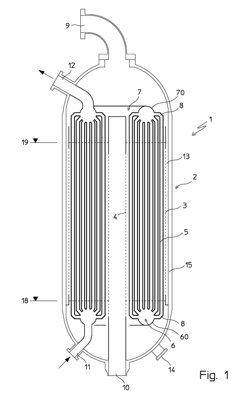
Figure 1 shows a vertical reactor 1 comprising a catalytic bed 2 and a tubular
heat exchanger immersed in said catalytic bed.
The catalytic. bed 2 is contained in a substantially annular space between a
cylindrical wall 3 and a central tube 4 coaxial with said wall 3. Both the
CA 02939854 2016-08-15
- 8 -
cylindrical wall 3 and the central tube 4 have at least part of the surface
perforated so as to allow the passage of the reagents and gaseous products.
The catalytic bed is supported by a basket (not shown) according to the art
known per se. The lines 18 and 19 indicate the volume filled with catalyst
during
conditions of normal use; below the line 18 there is usually inert material.
The tubular heat exchanger comprises essentially a straight tube bundle 5. The
tubes 5 are housed inside the annular space between the wall 3 and the central
tube 4.
The ends of the tubes are connected to two bodies 6 and 7 which act as a
distributor and a header for a heat exchange fluid. Each tube 5 is connected
to
the distributor 6 and the header 7 by means of suitably shaped end connectors
8. It should be noted that the tubular exchanger thus formed is without tube
plates. The distributor 6 and the header 7 in fact structurally support the
tubes
5, in addition to supplying and collecting the heat exchange fluid.
The main inlets and outlets of the reactor 1 comprise: a reagent inlet 9, an
outlet
10 for the reaction products; an inlet 11 and outlet 12 for the heat exchange
fluid. The reactor is also provided with at least one opening 14 for emptying
("drop-out") of the catalyst.
The wall 3 and the central tube 4 form respectively a distributor and a header
for the shell-side gases, which ensure an inward radial flow across the
catalytic
bed. In greater detail, the reagents entering via the inlet 9 flow into the
space 13
around the perforated wall 3 (between the wall 3 and the outer shell 15) and
cross the catalytic bed 2 with a substantially radial flow; inside the bed 2
the
desired chemical conversion takes place and the reaction products are
collected inside the central tube 4 which is in turn in communication with the
outlet 10.
The heat exchange fluid may supply heat or remove heat depending on the type
CA 02939854 2016-08-15
- 9 -
of reaction, i.e. endothermic or exothermic, and may undergo a phase change.
Fig, 1 for example refers to a reactor configuration for exothermic reaction
(for
example ammonia or methanol synthesis) in which the reaction heat is used to
produce steam. The fluid supplied to the inlet 11 is water which evaporates at
least partially inside the tubes 5.
Fig. 1 shows an embodiment in which the distributor 6 and the header 7 are
formed by toroidal bodies 60, 70.
Fig. 2 shows an embodiment in which one between the distributor and the
header, in the example the distributor 6, is formed by an ellipsoidal body 61.
Figs. 3, 4 show an example in which one between the distributor and the
header, in the example the header 7, is formed by a plurality of straight or
curved cylindrical elements 71 which are closed at both ends by end-plates 72.
Said cylindrical elements 71 are distributed alternately along two concentric
circumferences with radius r1 and r2 (Fig. 4) in order to maximise the use of
the space available, in particular of the cross-section of the shell of the
reactor
1.
The elements 71 have preferably a length of not more than 1 meter so that it
is
possible to reach the welds of the central tubes also without entering inside
them, after removal of one or both the end-plates 72. This constitutes an
advantage in.terms of dimensions (diameter) of the headers and in case the
welding operations require preheating of the materials where access by the
workman would be impossible.
The embodiments shown in Fig.1, Fig. 2 and Figs. 3 and 4 may be combined
with each other for the distributor 6 and the header 7, respectively.
As mentioned above, the tube bundle 5 is without tube plates, since the ends
of
the tubes are connected solely to the distributor 6 and header 7. In order to
CA 02939854 2016-08-15
- 10 -
ensure the stability of the tubes and in particular prevent vibrations, the
reactor
1 advantagedusly comprises a plurality of baffles for supporting the tubes,
distributed along the tube bundle at suitable intervals.
A preferred embodiment of said baffles is shown schematically in Fig. 6. The
baffles are formed by supporting elements such as rods 16 parallel to the
directrices 17 of the tubes. Said directrices 17 are lines joining together
the
centres of said tubes. The ends of the rods 16 may be fixed to a suitable
support frame or housing.
Advantageously, the rods 16 are spaced with a greater pitch than the rod-
baffles of the prior art which is shown, for comparison purposes, in Fig. 5.
According the prior art the rod-baffles have a distance which is twice the
pitch of
the tubes. The figure shows the conventional embodiment with pitch p between
tubes 5 and pitch 2p between the rods 16.
Fig. 6 shows'instead the bars with expanded pitch according to the invention,
for example with a pitch 3p. This arrangement of the rods at a greater
distance
has proved to be advantageous because it allows the tubes to be conveniently
supported, but at the same time it increases the free space in the bed 2 for
filling/emptying of the catalyst and for settling it.
The periodicity of the baffles is therefore equal to six baffles, namely
groups of
six baffle's with different orientation of the rods are arranged alternately
along
the reactor axis, and the sequence of six baffles is repeated periodically, if
necessary, until occupying the length of the entire-tube bundle.
Fig. 7 refers to tubes with a triangular pitch. The rods 16 are arranged along
directrices inclined of 00, 120 , 240 and form a rhomboid-like grid. The
periodicity of the baffles is equal to six. The rods 16 are spaced by a pitch
3p
and with a periodicity of six baffles indicated by the letters A-F. More
specifically, the first baffle comprises the rods A, the second baffle
comprises
=
CA 02939854 2016-08-15
- 11 -
the rods B, and so on, until the sixth baffle which comprises the rods F. In
the
figure it can be seen that the pitch between two rods of a baffle (for example
between two rods A) is three times the pitch of the tubes.
=