Note: Descriptions are shown in the official language in which they were submitted.
CA 02940072 2016-08-18
WO 2015/124180 PCT/EP2014/053240
1
Power cable termination device for gas-insulated switchgear
Technical field
The technology disclosed herein relates generally to the field of electrical
power cable
terminations, and in particular to high voltage direct current gas-insulated
switchgear
cable terminations.
Background
High Voltage Direct Current (HVDC) technology can be expected to play key part
in
future electrical grids. As the HVDC technology is maturing and the number of
installed DC links increases, the need and demand for improved DC switchgears
is
likely to arise. A gas-insulated switchgear (GIS) has much reduced physical
dimensions compared to more traditional open-air switchgear facilities and is
likely
to attract interest as a potential candidate for such improved DC switchgears,
in
particular as the GIS also has increased safety compared to the traditional
switchgear
facilities.
In order to connect a power cable to a GIS system a GIS cable termination is
needed.
For alternating current (AC) such terminations are available in a wide range
of
voltage levels. In contrast, for DC no such high voltage GIS cable
terminations are
available. The constrained dimensions of a GIS system make the realization of
a
robust GIS cable termination difficult, in particular in view of electrical
phenomena
unique for DC. For example, in comparison with cable terminations for AC
applications, cable terminations for DC applications encounter more difficult
electric
fields and these cable terminations thus has to be designed in view of being
able to
cope with DC fields. In addition, there are general difficulties in increasing
the
transmission power for DC cable systems, e.g. requiring the DC solutions to be
able to
handle thermal issues resulting from higher currents leading to higher
temperatures.
The higher voltages also entail exposing the cable terminations to higher
electric
fields, which dramatically increases the risk of material breakdown.
Insulation and mechanical performances are also important when designing cable
terminations and the electric field has to be controlled carefully on various
critical
locations.
2
Currently available DC cable terminations are free-standing in air and either
comprises solid/rubber materials at lower voltages, or fluid-filled/porcelain
insulators at increased voltages. Free-standing DC terminations require a
large
footprint due to long flashover distances in air.
Figure i is provided to further describe the difficulties involved when
developing GIS
cable termination devices for HVDC applications. Figure 1 is highly simplified
illustration, provided to illustrate the mentioned difficult electric fields.
The GIS
system, typically having a grounded housing, could be made much smaller than
the
io traditional switchgear system. In the figure 1, the leftmost part
illustrates
equipotential lines for the electric field created in a GIS chamber and the
rightmost
part illustrates equipotential lines for the electric field created in a
traditional
termination device. Looking first at the rightmost part; in the traditional
termination
device, there is an electric potential difference between the upper part (high
voltage)
of the termination device and the lower part (grounded), hence the illustrated
equipotential lines. In contrast, the housing of the GIS chamber is grounded,
i.e. no
electric potential difference, hence the illustrated equipotential lines for
this case
(refer to the leftmost part of the figure 1). The difficult electric fields
referred to
earlier thus comprise e.g. the difficulties in that the equipotential lines
are being kept
more or less parallel and close together, and the electric field thus being
much higher
than for the traditional terminal device, wherein the equipotential lines
separates, i.e.
the electric field decreases. When designing a cable termination device for
GIS, this
has to be handled, e.g. in view of avoiding increases in electric field in the
insulating
media (e.g. gas) causing breakdown.
There are thus several difficulties or problems involved when developing HVDC
GIS
cable terminations. Firstly there are electrical difficulties, e.g. the above
issue
described in relation to figure 1. Further, at the termination of a power
cable outer
screen (also denoted semicon edge) high electric fields are typically seen at
different
locations, e.g. in the solid materials, along interfaces between different
materials and
components, in locations where three components or layers interfaces each
other
(such locations also known as triple points) and in the insulating material
surrounding the conductor of the power cable, and there is also an increased
CA 2940072 2018-01-10
3
electrical field in insulating media, such as e.g. oil or gas, within the
cable
termination.
Furthermore, in DC applications, charge build-up at these interfaces between
different materials and components is a serious problem and the electric field
has to
be carefully controlled, particularly in various critical locations, such as
the above
mentioned locations.
Secondly there are thermal difficulties. The constrained geometry of the GIS
cable
termination may enhance local heating, which in turn may lead to thermal
breakdown of the power cable.
Thirdly there are mechanical difficulties. A mechanical connection between the
GIS
system and the GIS cable termination must be able to provide good electrical
contact
at various operation temperatures. Further, it must be solid enough to
withstand
handling and provide mechanical support to sensitive parts. Further still, the
termination must be adequately pressure sealed between different compartments
and
also to atmospheric pressure.
Summary of Invention
An object of the present disclosure is to solve or at least alleviate at least
one of the
above mentioned problems.
According to an aspect of the present invention, there is provided a power
cable termination
device for a high voltage direct current gas-insulated switchgear. The power
cable
termination device comprises an outer housing made of an electrically
conducting
material. The outer housing is fixedly connectable at first end thereof to the
high-
voltage direct current gas-insulated switchgear. The power cable termination
device
further comprises a terminal portion of a power cable the power cable
comprising an
electrical conductor, an electrically insulating layer circumferentially
surrounding the
electrical conductor, and a conductive shield circumferentially surrounding
the
insulating layer and the electrical conductor, wherein the conductive shield
is
CA 2940072 2018-01-10
3a
stripped off along a first part of the power cable; an electric field grading
system
comprising a resistive field grading material layer arranged circumferentially
around
the power cable such as to extend axially at least along a part of the
electrically
insulating layer and such as to cover the edge of the conductive shield where
the
conductive shield is terminated, the resistive field grading material layer
being in
electrical contact therewith. The power cable termination device further
comprises a
CA 2940072 2018-01-10
CA 02940072 2016-08-18
WO 2015/124180 PCT/EP2014/053240
4
connection device connectable to the gas-insulated switchgear and arranged to
provide mechanical support and electrical contact with the gas-insulated
switchgear.
The provided power cable termination allows for a HVDC cable to terminate
directly
inside a DC GIS system. By providing an electrical field grading system
adapted to
handle DC specific phenomena occurring in such GIS systems, electrical
difficulties
related to the providing of HV DC GIS cable terminations are overcome. The
power
cable termination is able to handle DC specific requirements, while still
meeting a
general desire of reduced size.
In an embodiment, the electric field grading system comprises an electric
field
control member arranged circumferentially surrounding the resistive field
grading
material layer at least along a part thereof, the electric field control
member being
arranged to control electrical field along the length of the power cable.
In a variation of the above embodiment, the electric field control member
comprises
a resistive field grading material.
In a variation of the above embodiment, the resistive field grading material
of the
electric field control member and the resistive field grading material of
resistive field
grading material layer is a non-linear resistive field grading material. The
resistive
field grading material layer and the electric field control member may be
manufactured as a single device, providing a cost-efficient solution and
avoiding an
electrical interface between the resistive field grading material layer and
the electric
field control member. The resistive field grading material of the resistive
field grading
material layer and the electric field control member, respectively, may be
chosen to
have same electrical properties, i.e. comprise of same field grading material.
In other
embodiments, the resistive field grading material of the resistive field
grading
material layer and the electric field control member, respectively, may be
chosen to
have different electrical properties.
In an embodiment, the power cable termination device comprises an inner shell
made of an electrically insulating material and fastened at a first end
thereof to the
connection device and at a second end thereof to a power cable receiving part
of the
outer housing. The inner shell provides mechanical support during installation
and
5
operation and also enables the use of different insulating media to be used,
i.e. a first
media closest to the power cable and another outside of the inner shell.
In a variation of the above embodiment, the inner shell is fastened at the
first end
thereof to the connection device via a first metal plate, and wherein the
inner shell is
fastened at the second end thereof to the outer housing via a second metal
plate. Such
embodiment achieves a cost reduction in that the same inner shell may be used
for
various applications.
In a variation of the above embodiment, the first metal plate and the second
metal
plate comprise a number of holes, through which an insulating medium can pass.
to This embodiment provides an increased circulation of the insulating
medium,
enabling an improved cooling of the power cable.
In an embodiment, the inner shell comprises a number of holes. A further still
improved circulation of the insulating medium is thereby enabled.
In an embodiment, the resistive field grading material layer is made of a non-
linear
resistive field grading material. The non-linear resistive field grading
material adapts
to the changing stresses created in the HVDC GIS and is dynamic in that the
conductivity increases at locations in which the electric field becomes high,
i.e. the
conductivity is a function of the electric field. Thereby DC specific
electrical
difficulties are handled.
In an embodiment, the electric field grading system comprises a conducting
electrode
fastened to a second end of the outer housing circumferentially surrounding
the
power cable and arranged a distance from the resistive field grading material
layer.
The conducting electrode provides geometric field control and a field-
enhancement
created at the edge where the conductive shield is cut off are avoided or at
least
mitigated.
In an embodiment, the housing comprises grounding means for being grounded in
use. This is the typical use case.
According to another aspect of the present invention, there is provided a high-
voltage direct current gas-insulated switchgear system comprising high-voltage
direct current gas-insulated switchgear and a power cable termination as
above.
CA 2940072 2018-01-10
,
5a
According to another aspect of the present invention, there is provided a
power cable
termination device for a high voltage direct current gas-insulated switchgear,
the
power cable termination device comprising:
an outer housing made of an electrically conducting material, the outer
housing being fixedly connectable at a first end thereof to the high-voltage
direct
current gas-insulated switchgear,
a terminal portion of a power cable, the power cable comprising an electrical
conductor, an electrically insulating layer circumferentially surrounding the
electrical
conductor, and a conductive shield circumferentially surrounding the
insulating layer
and the electrical conductor, wherein the conductive shield is stripped off
along a first
part of the power cable,
an electric field grading system comprising a resistive field grading material
layer, which is made of a non-linear resistive field grading material,
arranged
circumferentially around the power cable such as to extend axially at least
along a part
of the electrically insulating layer and such as to cover the edge of the
conductive
shield where the conductive shield is terminated, the resistive field grading
material
layer being in electrical contact therewith, and
a connection device connectable to the gas-insulated switchgear and arranged
to provide mechanical support and electrical contact with the gas-insulated
switchgear,
wherein the outer housing is filled with an insulating medium in the form of a
gas.
According to another aspect of the present invention, there is provided a
power cable
termination device for a high voltage direct current gas-insulated switchgear,
the
power cable termination device comprising:
an outer housing made of an electrically conducting material, the outer
housing being fixedly connectable at a first end thereof to the high-voltage
direct
current gas-insulated switchgear,
a terminal portion of a power cable, the power cable having an electrical
conductor, an electrically insulating layer circumferentially surrounding the
electrical
conductor, and a conductive shield circumferentially surrounding the
insulating layer
CA 2940072 2018-01-10
5b
and the electrical conductor, wherein the conductive shield is stripped off
along a first
part of the power cable,
an electric field grading system having a resistive field grading material
layer,
which is made of a non-linear resistive field grading material, arranged
circumferentially around the power cable such as to extend axially at least
along a part
of the electrically insulating layer and such as to cover the edge of the
conductive
shield where the conductive shield is terminated, the resistive field grading
material
layer being in electrical contact therewith,
a connection device connectable to the gas-insulated switchgear and arranged
to provide mechanical support and electrical contact with the gas-insulated
switchgear, and
an inner shell made of an electrically insulating material and fastened at a
first
end thereof to the connection device and at a second end thereof to a power
cable
receiving part of the outer housing.
According to another aspect of the present invention, there is provided a
power cable
termination device for a high voltage direct current gas-insulated switchgear,
the
power cable termination device comprising:
an outer housing made of an electrically conducting material, the outer
housing being fixedly connectable at a first end thereof to the high-voltage
direct
current gas-insulated switchgear,
a terminal portion of a power cable, the power cable comprising an electrical
conductor, an electrically insulating layer circumferentially surrounding the
electrical
conductor, and a conductive shield circumferentially surrounding the
insulating layer
and the electrical conductor, wherein the conductive shield is stripped off
along a first
part of the power cable.
an electric field grading system comprising a resistive field grading material
layer, which is made of a non-linear resistive field grading material,
arranged
circumferentially around the power cable such as to extend axially at least
along a part
of the electrically insulating layer and such as to cover the edge of the
conductive
shield where the conductive shield is terminated, the resistive field grading
material
layer being in electrical contact therewith, and
CA 2940072 2018-01-10
5c
a connection device connectable to the gas-insulated switchgear and arranged
to provide mechanical support and electrical contact with the gas-insulated
switchgear,
wherein the electric field grading system comprises a conducting electrode
fastened to a second end of the outer housing circumferentially surrounding
the
power cable and arranged a distance from the resistive field grading material
layer.
According to another aspect of the present invention, there is provided a high-
voltage
direct current gas-insulated switchgear system comprising a high-voltage
direct
current gas-insulated switchgear and a power cable termination device
including:
an outer housing made of an electrically conducting material, the outer
housing being fixedly connectable at a first end thereof to the high-voltage
direct
current gas-insulated switchgear,
a terminal portion of a power cable, the power cable comprising an electrical
conductor, an electrically insulating layer circumferentially surrounding the
electrical
conductor, and a conductive shield circumferentially surrounding the
insulating layer
and the electrical conductor, wherein the conductive shield is stripped off
along a first
part of the power cable,
an electric field grading system comprising a resistive field grading material
.. layer, which made of a non-linear resistive field grading material,
arranged
circumferentially around the power cable such as to extend axially at least
along a part
of the electrically insulating layer and such as to cover the edge of the
conductive
shield where the conductive shield is terminated, the resistive field grading
material
layer being in electrical contact therewith, and
a connection device connectable to the gas-insulated switchgear and arranged
to provide mechanical support and electrical contact with the gas-insulated
switchgear,
wherein the outer housing is filled with an insulating medium in the form of a
gas.
According to another aspect of the present invention, there is provided a
power cable
termination device for a high voltage direct current gas-insulated switchgear,
the
power cable termination device comprising:
CA 2940072 2018-11-14
5d
an outer housing made of an electrically conducting material, the outer
housing being fixedly connectable at a first end thereof to the high-voltage
direct
current gas-insulated switchgear;
a terminal portion of a power cable, the power cable comprising an electrical
conductor, an electrically insulating layer circumferentially surrounding the
electrical
conductor, and a conductive shield circumferentially surrounding the
insulating layer
and the electrical conductor;
an electric field grading system comprising a resistive field grading material
layer, arranged circumferentially around the power cable such as to extend
axially at
least along a part of the electrically insulating layer and, the resistive
field grading
material layer being in electrical contact therewith; and
a connection device connectable to the gas-insulated switchgear and arranged
to provide mechanical support and electrical contact with the gas-insulated
switchgear,
wherein the conductive shield is stripped off along a first part of the power
cable, the resistive field grading material layer being made of a non-linear
resistive
field grading material and arranged circumferentially around the power cable
such as
to cover an edge of the conductive shield where the conductive shield is
terminated,
wherein the power cable termination device further comprises an inner shell
made of
an electrically insulating material and fastened at a first end thereof to the
connection
device and at a second end thereof to a power cable receiving part of the
outer
housing, wherein the inner shell is fastened at the first end thereof to the
connection
device via a first metal plate, and wherein the inner shell is fastened at the
second end
thereof to the outer housing via a second metal plate.
Further features and advantages of the present disclosure will become clear
upon
reading the following description and the accompanying drawings.
CA 2940072 2018-11-14
,
6
Brief description of the drawings
Figure 1 illustrates the electric field in a GIS chamber and a traditional
termination
device.
Figure 2 illustrates a cable termination in accordance with an embodiment of
the
present disclosure.
Figure 3 illustrates a cable termination in accordance with an embodiment of
the
present disclosure.
Figure 4 illustrates a cable termination in accordance with an embodiment of
the
present disclosure.
Figure 5 illustrates a cable termination in accordance with an embodiment of
the
present disclosure.
Figure 6 illustrates a cable termination in accordance with an embodiment of
the
present disclosure.
Figure 7 illustrates a cable termination in accordance with an embodiment of
the
present disclosure.
Figures 8A and 8B illustrate in different views a power cable termination.
Figure 9 illustrates a stress cone.
Detailed description
In the following description, for purposes of explanation and not limitation,
specific
zo details are set forth such as particular materials, interfaces,
techniques, etc. in order
to provide a thorough understanding. In other instances, detailed descriptions
of
well-known devices, circuits, and methods are omitted so as not to obscure the
description with unnecessary detail. Same reference numerals refer to same or
similar elements throughout the description.
Briefly, the present disclosure provides in various aspects a HVDC cable
termination
design for GIS.
CA 2940072 2018-01-10
CA 02940072 2016-08-18
WO 2015/124180 PCT/EP2014/053240
7
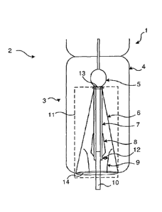
Figure 2 illustrates a cable termination in accordance with an embodiment of
the
present disclosure. A power cable to is to be connected to a gas-insulated
switchgear
1. The power cable to may be a cable such as the power cable described with
reference
to figures 8A and 8B. In figure 2, part of such gas-insulated switchgear (GIS)
us
.. illustrated. The GIS 1 may be a conventional switchgear facility comprising
for
example switches, busbars, transformers etc. (not illustrated).
A GIS termination chamber 3 (also denoted a power cable termination device 3
herein) is connectable to the GIS 1. The GIS termination chamber 3 comprises a
housing, in the following denoted outer shell 4, which is fixed to the GIS 1.
The outer
to .. shell 4 provides mechanical support for an electric field grading system
11 and also
separation from an atmosphere outside the outer shell 4. The outer shell 4
comprises
an electrically conductive housing, e.g. being made of an electrically
conducting
material. The outer shell 4 may comprise means for being grounded in use,
which is
the typical use case.
.. A GIS system 2, as the term is used in the present disclosure, comprises
the GIS 1 and
the GIS termination chamber 3.
The GIS termination chamber 3 comprises, within the outer shell 4, the
electric field
grading system it, a connection device 5 for connecting the electric field
grading
system 11 to the GIS 1 and a termination part of a power cable to. The
connection
device 5 may be an electrically shielded mechanical connection providing
electrical
contact and mechanical support. The connection device 5 should be designed in
view
of the being able to handle the electric field as described in relation to
figure 1. The
connection device 5 may for example be provided with field control devices
that are
designed so as to be able to handle such electric fields.
.. The connection device 5 may designed in view of rendering an installation
easier, in
particular when the electric field grading system it has been assembled ex-
situ and is
thereafter installed into the GIS termination chamber 3. Examples of such
design
aspect comprise the connection device 5 being e.g. a female connector to be
attached
to a corresponding male connector arranged at the GIS 2, or the other way
around,
.. i.e. the connection device being a male connector while the corresponding
female
connector arranged at the GIS 1. The use of a guide pin or the like may
further
facilitate the installation. Providing the connection device 5 with contact
springs for
CA 02940072 2016-08-18
WO 2015/124180 PCT/EP2014/053240
8
electrical connection between such male and female connectors enable a secure
electrical contact by the flexibility of springs; the flexibility compensating
for
differences in volume of the components caused by temperature changes.
The connection device 5 overcomes at least some of the earlier mentioned
mechanical
difficulties by providing good electrical contact at various operation
temperatures. In
an embodiment, at least a first (upper) part of the connection device 5 is
made of a
material with high electrical and thermal conductivity, e.g. a metal, with a
rather
large surface area. The first part being made of metal and having a large
surface area
towards the surrounding cooling medium, e.g. gas, enables such cooling.
It is noted that the connection device 5 may include further components, e.g.
fitting
sleeves, sealing sleeves etc.
Turning briefly to figures 8A and 8B, illustrating a power cable, and in
particular the
termination thereof, which will be described next. Figure 8A illustrates a
power cable
10, and figure 8B is a cross-section view along line A-A of figure 8A and it
is noted
that the relative thicknesses of the various layers may differ from an actual
power
cable. As illustrated in figure 8B, the power cable 10 comprises at least an
inner
electrical conductor 101, e.g. made of copper and comprising e.g. a number of
stranded conductors, an electrically insulating layer 103 circumferentially
surrounding the electrical conductor 101, and a conductive shield 104 (also
denoted
outer semicon), which circumferentially surrounds the electrically insulating
layer
103 and the electrical conductor 101. The conductive shield 104 may be
connected to
ground and arranged to equalize dielectric stress on the insulating layer 103.
The
power cable 10 also comprises an electrically insulating outer jacket 105. As
indicated
in the figure 8B, there may be further layers as well. For instance, there is
typically an
inner screen 102 between the electrical conductor 101 and the electrically
insulating
layer 103, i.e. such inner screen 102 (also denoted inner semicon)
circumferentially
surrounds the electrical conductor 101, and is circumferentially surrounded by
the
electrically insulating layer 103. As a particular example of insulation layer
material,
cross-linked polyethylene (XLPE) can be mentioned. Still other layers may also
be
present, e.g. a layer of metal armoring.
When electrically connecting the power cable 10 to the switchgear, or more
generally
to other electric equipment, the power cable 10 is cut off (terminated) and
all layers
CA 02940072 2016-08-18
WO 2015/124180 PCT/EP2014/053240
9
are stripped off in order to expose the conductor 101, from the cut off end
and along a
first length. Along this first length, the termination end of the power cable
10 thus
comprises only the exposed conductor 101. Thereby the conductor 101 may be
connected to electric equipment, which in the present disclosure may comprise
a
receiving end of the gas-insulated switchgear 1. Further, the power cable 10
is partly
stripped off along a second length thereof (following the first length of
exposed
conductor 101), in particular down to the electrically insulating layer 103.
This partial
stripping along the second length results in a disruption of the geometry of
the power
cable in, that is, a geometry change at a section between the end of the
second length
of exposed electrically insulating layer 103 and the conductive shield 104
(outer
semicon). In this geometry disruption, i.e. at the (outer) semicon edge, there
will be a
substantial stress concentration if not taken care of, in particular high
electric field
and electric field stress. At the termination of the conductive shield 104
(the outer
semicon), i.e. where the conductive shield 104 ends and a circumferential edge
(also
denoted semicon edge) is formed, there is a particularly high electric field
and electric
stress. To alleviate such electric fields and field stress, a field grading
material (FGM)
layer 7 is arranged to circumferentially surround the semicon edge of the
power cable
10, i.e. to surround the edge of the conductive shield 104. This efficiently
controls the
electric field distribution and reduces the electric field stress. In the
figure 8A, the
.. FGM layer 7 is illustrated as covering the edge (semicon edge) between the
part of the
power cable 10 where the conductive shield 104 has been stripped off to the
part of
the power cable 10 which is still shielded, i.e. where the conductive shield
104 is
present. Although illustrated as ending close to the disrupted conductive
shield 104
(semicon edge), the FGM layer 7 may typically be arranged to cover the
electrically
insulating layer 103 along its entire axial length.
Reverting to figure 2, in this embodiment the electric field grading system 11
is
mounted within an inner shell 6. The electrical field grading system 11 is in
particular
arranged to handle electrical difficulties arising for HVDC GIS cable
terminations,
and comprises at least a resistive field grading layer, in particular a field
grading
material (FGM) layer 7 (compare figure 8A). The FGM is preferably a non-linear
resistive FGM that changes its resistance dependent on the electric field. The
present
disclosure thus provides a solution for handling electrical difficulties
arising when
providing a cable termination for a HVDC GIS. The non-linear resistive FGM
adapts
CA 02940072 2016-08-18
WO 2015/124180 PCT/EP2014/053240
to the changing stresses created in the DC application (in particular the HVDC
GIS
application), and can be seen as a dynamic electric stress grading system. The
resistive non-linear field grading material may also respond dynamically to
voltage
impulse shapes by adapting the conductivity in a non-linear way to the
electric field
5 stress experienced. A field control member 8, described more in detail
later, may be
provided, which may handle such impulses (i.e. fast and high impulses where
the
FGM response may not suffice), while the FGM layer 7 may be provided to handle
lower and slower impulse voltages. The non-linear resistive material is
dynamic in
that the conductivity increases at locations in which the electric field
becomes high,
10 i.e. the conductivity is a function of the electric field.
As mentioned earlier, the FGM layer 7 is arranged to cover the semicon edge
(compare FGM layer 7 covering the edge of the conductive shield 104 of figure
8A).
That is, the FGM layer 7 is arranged around the conductive shield (compare
reference
numeral 104 of figure 8B) of the power cable lo and in electric contact with
the
conductive shield 104. The FGM layer 7 thereby connects high voltage on the
top
connection to ground, the conductive shield 104 being grounded. It is noted
that in
some embodiments, the FGM layer 7 is arranged around the conductive shield
along
a certain axial length thereof, but not all the way to the top connection. The
FGM
layer 7 may be adapted in view of the particular application at hand by
varying its
thickness along the length thereof and/or by adapting the FGM to have a
desired
electric conductivity to meet the expected electrical field stresses of the
particular
application. The FGM may be characterized in different ways. The conductivity
of the
non-linear FGM depends on the electric field and varies greatly, in particular
to a
much larger extent than other materials. The FGM has a field-dependent
conductivity
that may increases strongly from a low conductivity value to a high
conductivity
value, i.e. changes from being highly insulating (high resistance) to being
highly
conductive (low resistance). As a particular, non-limiting example the FGM may
have
a conductivity in the region of io-16 or 10-14 Siemens per meter (S/m) in case
of being
exposed to a low electric field, and change to have a conductivity in the
region of 10-3
S/m or 0.1 S/m in case of being exposed to a high electric field. The FGM may
for
example comprise e.g. SiC and/or ZnO and/or carbon black filled polymers, and
the
characteristics of the FGM may be designed to comprise a certain conductivity.
The
FGM may also be designed to have a permittivity (also denoted dielectric
constant)
CA 02940072 2016-08-18
WO 2015/124180 PCT/EP2014/053240
11
set in view of obtaining some capacitive field grading, e.g. by choosing
filler material
and concentration of the chosen filler material accordingly.
The electrical field grading system 11 may further comprise an electric field
control
member 8, also denoted stress cone. The stress cone 8 is arranged surrounding
the
FGM layer 7, as illustrated schematically in e.g. figure 2. The stress cone 8
is
illustrated more in detail in figure 9, showing the stress cone 8 in a side
view partly in
section. The stress cone 8 is arranged to provide geometrical, resistive
and/or
capacitive field control, and comprises e.g. insulating or stress-grading
rubber
combined with conducting or semiconducting rubber. The conducting or
semiconducting rubber part of the stress cone, indicated at reference numeral
8b,
may have the shape of a cylinder at a first end thereof and be arranged around
the
power cable 10 along this end, and in particular surrounding the FGM layer 7.
The
semiconducting rubber part 8b may at a second end thereof deviate from the
cylinder
form, and instead follow the surface of the insulating rubber part.The
insulating
rubber part 8a of the stress cone 8, which is indicated at reference numeral
8a may
for example have an essentially cone-shaped form, the form being adapted for
the
application at hand.
The electrical field grading system 11 may further comprise a metallic or
conducting
electrode 9 placed a certain distance away from the FGM layer 7. The
conducting
electrode 9 may be fastened to the outer housing, and in particular to the
power cable
receiving end (in the figures, illustrated as the lower end). The conducting
electrode 9
may be arranged to circumferentially surround the power cable and arranged a
distance from the resistive field grading material layer 7. It is noted that
the
conducting electrode may be fastened elsewhere within the outer housing, such
as
e.g. fastened to the power cable or fastened to the (vertical) walls of the
outer
housing. In embodiments comprising both the stress cone 8 and the conducting
electrode 9, there is a distance between these devices as well, i.e. the
conducting
electrode 9 is arranged also a distance away from the stress cone 8.
The electrode 9 is denoted screening electrode and provides geometric field
control
and by placing the screening electrode 9 a distance (e.g. a few centimeters,
as a
particular example about 5-10 cm may be mentioned) away from the FGM layer 7,
a
field-enhancement at the triple point is avoided; the most critical triple
points being
CA 02940072 2016-08-18
WO 2015/124180 PCT/EP2014/053240
12
created at the semicon edge: FGM layer 7/ part of the power cable with
conductive
shield/part of power cable without conductive shield (i.e. cable insulation
layer) and
at FGM layer 7/ semi-conducting rubber of the stress cone 8 /insulating
material of
the stress cone 8. It is noted that there are additional triple points as
well. The gap
between the FGM layer 7 and the screening electrode is indicated at reference
numeral 12 in figure 2.
The electrical field grading system 11, comprising the above mentioned FGM
layer 7,
and optionally the stress cone 8 and/or the conducting electrode 9, is
designed to
overcome one or more of the earlier indicated electrical difficulties involved
when
developing HVDC GIS cable terminations. The high electrical fields are reduced
to
great extent by the FGM layer 7, which may be adapted in view of the
application at
hand, for example by adapting the thickness thereof. The FGM layer 7 provides
resistive field grading of the electrical field, and the electrical properties
of the FGM
may be chosen so that the electrical field becomes distributed within the
material and
spread over a larger region, whereby the electric stress is greatly reduced. A
non-
linear FGM exhibits a non-linear electrical resistance that decreases with an
increasing electric field. Typically, the closer the semicon edge, the higher
the electric
field is in the FGM layer 7. By using non-linear FGM layer 7, the voltage drop
along
the FGM layer 7 will be more uniformly distributed in the axial direction
since the
electrical resistance in the FGM layer 7 will decrease with increasing
electric field.
The high electrical fields at the semicon edge, seen in the solid materials,
along
interfaces between different materials and components, in locations where
three
components or layers interfaces each other (such locations also known as
triple
points) and in the insulating material surrounding the conductor of the power
cable,
are thereby handled.
Still with reference to figure 2, the GIS termination chamber 3 further
comprises, in
various embodiments, the earlier mentioned inner shell 6. The inner shell 6
is, when
installed and in use, in direct contact with high voltage and ground, and it
is therefore
made of an electrically insulating material, e.g. composite isolant. The inner
shell 6 is
preferably a composite insulator owing to the low weight thereof, but it is
noted that
other materials may be used, for example porcelain. The inner shell 6 is
arranged to
provide mechanical support during installation and operation. In particular,
the
electric field grading system 11 may, as mentioned earlier, be assembled ex-
situ and
CA 02940072 2016-08-18
WO 2015/124180 PCT/EP2014/053240
13
thereafter be installed into the GIS termination chamber 3, and the inner
shell 6
provides mechanical support during such installation and thereby also
facilitates the
installation.
The inner shell 6 further serves as a pressure barrier between the electrical
field
grading system ii and the outer shell 4. The inner shell 6 thereby enables the
use of
different insulating media within the inner shell 6 and in the volume between
the
outside of the inner shell 6 and inside the outer shell 4, and also at
different
pressures. The inner shell 6 may be designed in view of handling such pressure
differences, by e.g. adapting the thickness of the inner shell 6 to handle
such pressure
differences.
The respective volumes (or chambers) created by the outer shell 4 and the
inner shell
6 may be hermetically sealed from each other, as well as from the GIS 1, and
the
insulating medium within the inner shell 6 and the insulating medium in the
above
mentioned volume may thus be chosen independently. For practical purposes, the
outer shell 4 may be filled with the same insulation medium as the GIS 1, and
SF6
(Sulfur hexafluoride) gas is preferably used owing to its high insulation
strength, low
weight and easy handling. Although depending on the application at hand, the
insulation medium of the inner shell 6 (i.e. within the volume mentioned
above) may
be different than the insulation medium outside the inner shell 6. The GIS
termination chamber is, according to various embodiments of the present
disclosure,
advantageous in that it may thereby easily be adapted for use with oil or with
gas. The
insulation medium of the inner shell 6 may for example be SF6 or oil. Oil has
good
thermal properties and is able to transfer heat to a higher degree than SF6.
The inner shell 6 is also arranged to center and keep the power cable lo
stretched.
The inner shell 6 may have a cone-shaped form, in particular having the shape
of a
cut-off cone with a first diameter at a first end (in the figure 2, its
uppermost end),
the first end being fastened to the connection device 5, i.e. mechanically
connected
thereto, and a second diameter at a second end (in the figure 2, its lower
end), the
second end of the inner shell 6 e.g. being connected to the outer shell 4 at
an entrance
part for the power cable 10. The first diameter may thus be smaller than the
second
diameter. The inner shell 6 may be fastened at the first end thereof (in the
figure 2, its
upper end) to the connection device 5 and at an opposite end, i.e. the second
end
CA 02940072 2016-08-18
WO 2015/124180 PCT/EP2014/053240
14
thereof (in the figure 2, its lower end) to the outer shell 4, in particular
to a power
cable receiving part, i.e. the part where the power cable enters the outer
shell 4.
However, in another embodiment, the inner shell 6 is arranged on metal plates,
in
particular fastened at its first end to a first metal plate (in the figure,
upper end),
indicated at reference numeral 13, and at its second end to a second metal
plate (in
the figure, lower end), indicated at reference numeral 14. The first (upper)
metal plate
13 is then fastened to the connection device 5, and the second (lower) metal
plate 14
is fastened to the part of the outer shell 4 wherein the power cable 10 enters
the outer
shell 4. Such embodiment enables the use of same inner shell 6 for different
.. embodiments, as will be described later, requiring only the metal plates
13, 14 to be
adapted to the different embodiments. Although the inner shell 6 is described
and
illustrated as having a cone-shaped form, other forms are also possible, e.g.
a cylinder
shaped inner shell. It is also noted that the inner shell 6, when having the
shape of a
cut-off cone, could be arranged in the opposite way to the one described
above. That
is, the second diameter could be smaller than the first diameter.
In a further aspect, the inner shell 6 may be adapted to handle thermal issues
as well
as electrical issues by designing the inner shell accordingly. In particular,
angles of
the inner shell when having the shape of a cone or cut-off cone may be varied
so as to
avoid "hotspots" (i.e. volumes/areas within increased temperature), the angles
referring to the angles between the walls of the inner shell and a vertical
line. Thus,
the radiuses (/diameter) of the upper first part and the lower second part of
the inner
shell may be increased or decreased in view of improving thermal convection so
that
the end of the power cable in is cooled to a larger extent and "hotspots" are
avoided.
This choosing of diameter corresponds to increasing or decreasing the angle
between
the power cable 10 and the inner shell 6, wherein an acute angle typically
entails an
enhanced risk of hotspots being created.
In another aspect, the design of the inner shell 6 may be adapted in view of
electric
breakdown. In particular, the inner shell 6 provides two interfaces, where
different
media meet: the interface between the gas and the outside of the inner shell
6, and
the interface between the inside of the inner shell 6 and the gas. There is a
risk of
interfacial breakdown at both these interfaces, which breakdown risk may be
reduced
by adapting the mentioned angle and/or shape of the inner shell so as to
minimize
the part of the electric field that causes this type of breakdown.
15
Figure 3 illustrates an embodiment of the present disclosure. In this
embodiment, the
inner shell 6 is hermetically sealed and filled with oil. Oil cools the power
cable 10
more efficiently than SF6, and since the power cable 10 may be heated
substantially
when providing high currents, this embodiment is advantageous in applications
in
which temperature control is important. The housing 4 may also comprise
grounding
means 20 for being grounded in use. Although not shown in Figures 2 and 4 to 7
for
simplicity, each of the housings 4 therein may comprise grounding means 20 to
provide grounding.
Figure 4 illustrates an embodiment of the present disclosure. In this
embodiment, the
inner shell 6 is filled with SF6 or another gas. Gas may be allowed to
circulate
between the space within the inner shell 6 and the space outside the inner
shell 6 (i.e.
space between the inner shell 6 and the outer shell 4). Such gas circulation
may be
accomplished by designing the inner shell 6 with holes. In another embodiment,
the
inner shell 6 has no holes, and the gas is instead circulated by connecting
the inner
shell 6 and the outer shell 4 to each other by the earlier mentioned upper
metal plate
13 and a lower metal plate 14, which are provided with holes. The gas then
flows into
the space within the inner shell 6 through the holes of the lower metal plate
14 and
exits the same space through the holes of the upper metal plate 13. The arrows
in
figure 4 indicate a gas flow according to the latter embodiment. The gas
within the
inner shell 6 closest to the power cable 10 is heated (by increased
temperature of the
power cable 1.0 at high currents) to a larger extent than the gas in the space
outside
the inner shell 6. The circulation of the gas thereby provides a better
cooling of the
power cable to by circulating the warmer gas within the inner shell 6 to the
larger
space outside the inner shell, which also has gas having lower temperature,
which low
temperature gas is thus circulated to within the inner shell 6.
One or more of the earlier indicated thermal difficulties involved when
developing
HVDC GIS cable terminations is overcome by the above embodiments. In
particular,
enhanced local heating, which in turn may lead to thermal breakdown of the
power
cable, may be avoided.
CA 2940072 2018-01-10
15a
Figure 5 illustrates an embodiment of the present disclosure. In this
embodiment, the
stress cone 8 is made of stress-grading material, and in particular the
insulating
rubber part of the stress cone 8a (refers to earlier description of the stress
cone 8 and
figure 9). The stress-grading material may for example be non-linear resistive
FGM.
The FGM layer 7 and the stress cone 8 may thus both comprise non-linear
resistive
FGM. The respective FGM may have same or different electrical properties, e.g.
CA 2940072 2018-01-10
CA 02940072 2016-08-18
WO 2015/124180 PCT/EP2014/053240
16
having same or different dielectric constants. For the FGM layer 7, arranged
closer to
the power cable 10 than the stress cone 8, a material having higher electrical
conductivity (lower resistivity) may be chosen than the FGM of the stress cone
8. The
FGM layer 7 and the stress cone 8 may be manufactured as an integrated body
made
of FGM. One electric interface may thereby be omitted, i.e. such stress cone 8
avoids
a triple point to be formed in an electrically sensitive part of the electric
field grading
system ii. One or more of the earlier indicated electrical difficulties
involved when
developing HVDC GIS cable terminations is thus overcome also by such
embodiment.
In particular, by using same material for the stress cone 8 and the FGM layer
7,
difficulties relating to charge build-up are avoided. That is, the use of same
material
in effect eliminates one electrical interface between components
conventionally being
of different material and thus having different material properties, i.e. the
interface
between the stress cone 8 and the FGM layer 7, avoids corresponding high
electrical
fields.
Figure 6 illustrates an embodiment of the present disclosure. In this
embodiment, the
screening electrode 9 (refer e.g. to figure 2) is omitted. Depending on the
requirements of the GIS termination chamber 3 and material characteristic of
the
FGM layer 7, the screening electrode 9 may be omitted from any of the
described
embodiments.
The embodiments described thus far have been illustrated as comprising the
inner
shell 6, which in turn comprises the electric field grading system. The
installation of
the electric field grading system ii within the inner shell 6 has advantages
such as the
inner shell 6 providing mechanical support and protection of the electric
field grading
system 11.
Figure 7 illustrates an embodiment of the present disclosure. In this
embodiment, the
inner shell 6 is omitted. The electric stress grading system ii used in this
embodiment may be designed in accordance with any of the described
embodiments,
i.e. comprising at least the FGM layer 7, and optionally also one or both of
the stress
cone 8 and the conducting electrode 9. Such embodiments may provide still
improved thermal performance. Typically, a cable system, including accessories
(electric field grading system etc.), is designed to operate close to the
limit of any
available cooling. Local hotspots caused by heated gas or oil may thus trigger
an
CA 02940072 2016-08-18
WO 2015/124180
PCT/EP2014/053240
17
electric breakdown. Ideally, the accessories should be designed more
conservatively
than the power cable 10 in order to obtain optimal power transmission, since
the
power cable 10 is most often designed to operate close to its thermal limits.
By
omitting the inner shell 6, the smaller gas volume inside the inner shell 6 is
removed
and a further improved convective cooling of the power cable 10 is enabled by
this
embodiment. The cable termination part is, in this embodiment, located within
a
larger volume, which permits a larger gas volume to circulate more freely and
the
convective cooling of the power cable 10 is improved further.
Furthermore, the embodiment of figure 7 also eliminates two interfaces, in
particular
the interface between the gas and the outside of the inner shell 6, and the
interface
between the inside of the inner shell 6 and the gas. There is a risk of
interfacial
breakdown at both these interfaces, which risk is thus eliminated by the
present
embodiment. This embodiment provides a cost-efficient solution; the cost of
the
inner shell 6, e.g. made of composite isolant, is avoided, and the reduced
complexity
provides further cost savings by enabling an easier installation and also
weight
reduction.
There are several DC specific unique phenomenon, for example polarization
phenomenon, the charge build-up at electrical interfaces of the cable
termination,
electrical charges moving within the DC field, gas moving and thus moving
electrical
charges. The various embodiments overcome such difficulties relating to the DC
specific phenomenon involved when developing HVDC GIS cable terminations:
electrical, thermal as well as mechanical difficulties.
The various features of the embodiments described may be combined in different
ways, also in ways not explicitly mentioned herein. A power cable termination
device
3 for a high-voltage direct current gas-insulated switchgear 1 is thus
provided. The
power cable termination device 3 comprises an outer housing 4 made of an
electrically conducting material. The outer housing 4 is fixedly connectable
at a first
end thereof to a gas-insulated switchgear system 2 of the high-voltage direct
current
gas-insulated switchgear 1.
The power cable termination device 3 comprises a terminal portion of a power
cable
10. The power cable 10 comprises an electrical conductor 101, an electrically
insulating layer 103 circumferentially surrounding the electrical conductor
101, and a
CA 02940072 2016-08-18
WO 2015/124180 PCT/EP2014/053240
18
conductive shield 104 circumferentially surrounding the insulating layer 103
and the
electrical conductor 101, wherein the conductive shield 104 is stripped off
along a first
part of the power cable 10.
The power cable termination device 3 comprises an electric field grading
system 11
.. comprising a resistive field grading material layer 7 arranged
circumferentially
around the power cable 10 such as to extend axially at least along a part of
the
electrically insulating layer 103 and such as to cover at least part of the
first part of
the power cable lo and to cover the edge of the conductive shield 104 where
the
conductive shield 104 is terminated, the resistive field grading material
layer 7 being
in electrical contact therewith.
The power cable termination device 3 comprises a connection device 5
connectable to
the gas-insulated switchgear system 2 and arranged to provide mechanical
support
and electrical contact with the gas-insulated switchgear system 2.
The present disclosure also encompasses a high-voltage direct current gas-
insulated
switchgear system 2 comprising the high- voltage direct current gas-insulated
switchgear 1 and a power cable termination device 3 as has described in
various
embodiments.
The invention has mainly been described herein with reference to various
embodiments. However, as is appreciated by a person skilled in the art, other
embodiments than the particular ones disclosed herein are equally possible
within
the scope of the invention, as defined by the appended patent claims.