Note: Descriptions are shown in the official language in which they were submitted.
CA 02940248 2016-08-19
WO 2015/127401
PCT/US2015/017164
SYSTEM AND METHOD FOR THERAPEUTIC MANAGEMENT OF UNPRODUCTIVE
COUGH
RELATED APPLICATION DATA
The present application claims priority to U.S.
Provisional Application Serial No. 61/943,210, filed
February 21, 2014. The foregoing application is hereby
incorporated by reference into the present application in
its entirety.
FIELD OF THE INVENTION
The present invention relates generally to chronic
cough and, in particular, to an implantable configuration
for providing warming of cervical vagus nerves for the
treatment of chronic cough.
BACKGROUND
The cough reflex is one of several defensive reflexes
that serve to protect the airways from the potentially
damaging effects of inhaled particulate matter,
aeroallergens, pathogens, aspirate and accumulated
secretions. In some airways diseases, cough may become
excessive and non-productive, and is potentially harmful to
the airway mucosa.
As described in the review entitled Epidemiology of
Cough by Alyn Morrice in 2002, (Chung, K., W. JG, et al.,
1
CA 02940248 2016-08-19
WO 2015/127401
PCT/US2015/017164
Eds. (2003). Cough: Causes, Mechanisms and Therapy. Malden,
Mass, Blackwell Publishing Lid.; incorporated by reference
herein in its entirety) cough is a universal experience
common to us all. It is also the commonest symptom for
which medical advice is sought. For the purpose of
classification cough may be divided into defined, acute,
self- limiting episodes and chronic persistent cough. This
distinction is clinically useful since the aetiology of the
two syndromes is very different. An arbitrary cut-off of 8
weeks is taken to separate acute from chronic cough.
The three common causes of chronic cough.
All of the reported series from tertiary referral
centres identify the same three common causes of cough.
This diagnostic triad underlies the vast majority of
chronic cough seen within the population. The problem of
the high morbidity from chronic cough is the failure of
doctors, both generalists and specialists, to recognize
that cough as an isolated symptom may be generated from any
of three anatomical areas.
Cough-predominant asthma
The term cough-predominant asthma has been introduced
to illustrate that cough may be one facet of an asthma
syndrome which is variously represented in individual
patients. In classic asthma where bronchoconstriction, and
conversely bronchodilator response, can be demonstrated
cough may be an additional and important feature. However,
cough as an isolated symptom without bronchoconstriction or
breathlessness, but with the characteristic pathological
features of asthmatic airway inflammation, is the other end
of the spectrum. This so-called cough variant asthma is
2
CA 02940248 2016-08-19
WO 2015/127401
PCT/US2015/017164
merely one end of a continuum. The term cough-predominant
asthma may be preferred since this terminology includes
patients in whom the major problem is cough but who also
illustrate some or all of the other features of classic
asthma.
Between a quarter and a third of patients presenting
to a tertiary referral center with chronic cough will be
suffering from cough-predominant asthma. This rate of
detection probably does not reflect the prevalence of cough-
predominant asthma since many patients, particularly those
who have features of classic asthma, are diagnosed and
treated in the community. Indeed it is unusual for patients
with chronic cough to be seen in tertiary clinics who have
not had an unsuccessful trial of inhaled medication. The
reasons for failure of therapy, even when the underlying
diagnosis is of cough-predominant asthma, are all those
usually associated with poor asthma control: compliance,
poor inhaler technique, inappropriate choice of device,
etc. In addition there are other features of cough-
predominant asthma, which unless recognized, lead to
failure of therapy. Clearly the usual diagnostic measures
of reversibility testing or home peak How monitoring are
frequently unhelpful. Even methacholine challenge may not
identify patients who respond adequately to corticosteroid
therapy since those with eosinophilic bronchitis are not
hypersensitive. Whilst sputum examination in expert hands
clearly has a role the methodological difficulties obviate
its routine use. Ultimately, the diagnosis and therefore
prevalence of cough-predominant asthma rests on the use of
a therapeutic trial of antiasthma medication. Here again
the differences between cough-predominant asthma and
3
CA 02940248 2016-08-19
WO 2015/127401
PCT/US2015/017164
classic asthma may lead to confusion. Since bronchospasm
may only be a minor feature or even absent, add-on therapy
with long-acting 13-agonists rarely proves successful and
leukotriene antagonists may be the preferred add-on
therapy. The response to leukotriene antagonists may
illustrate the hypothesized role of lipoxygenase products
in the direct modulation of the putative VR1 cough
receptor. Ultimately, diagnosis of cough- predominant
asthma may rely on the demonstration of a response to
parenteral steroids.
The oesophagus and cough
A considerable portion of patients presenting with
chronic cough have a disorder of the oesophagus. It is
poorly recognized by many physicians, yet cough as the sole
presentation of gastro-oesophageal reflux has been well
described. In addition to reflux it is becoming increasingly
clear that a number of oesophageal disorders, broadly
classified as dysmotility and including abnormal peristalsis
and abnormal lower oesophageal sphincter tone, may give
rise to cough. That acid reflux alone is not the cause of
cough in oesophageal disease explains the partial response
seen in many patients with even high doses of proton pump
inhibitors. As with other causes of cough, diagnosis may be
difficult because there can be few clues from the history.
However, whilst there is some disagreement, in individual
patients there may be a strong association with other
symptoms, particularly heartburn. More unusual
characteristics such as an association with hoarseness,
choking sensation and postnasal symptoms are increasingly
recognized as being part of a reflux phenomenon by ENT
specialists. Indeed, a striking reduction of cough during
4
CA 02940248 2016-08-19
WO 2015/127401
PCT/US2015/017164
sleep, which initially may be thought to count against a
diagnosis of oesophageal cough, may indicate an oesophageal
origin. Lower oesophageal sphincter pressure increases
physiologically in recumbency preventing reflux in the early
stages of the disease. The clues to the diagnosis of cough
of oesophageal origin may be obtained by looking for
associations between food, eating and cough.
Rhinitis and postnasal drip
There is marked geographical variation in the
incidence of rhinitis and postnasal drip in the reported
series of patients presenting to cough clinics. Patients in
the Americas present with symptoms of postnasal drip in up
to 50% of cases, whereas rhinitis is reported in
approximately 10% in most European experience. The
difference for this may be in part societal in that
patients from North America are far more likely to describe
upper respiratory tract symptoms as postnasal drip. In
addition, the diagnosis of postnasal drip or rhinitis is
frequently accepted because of a response to 'specific
therapy' with broad-spectrum, centrally acting
antihistamines and systemic decongestants. Such therapy may
act in upper airway disease and in asthma. Centrally acting
antihistamines may work either on the central pathways of
the cough or through a sedating mechanism unrelated to the
anatomical site of cough generation.
Until such problems in the definition of postnasal drip
and its subsequent specific diagnosis are resolved, rhinitis
or rhinosinusitis is probably the preferred term describing
this syndrome.
Cough in cancer patients
CA 02940248 2016-08-19
WO 2015/127401
PCT/US2015/017164
As reviewed by Ahmedazai and Ahmed (Chung, JG et al.
2003) in the cancer patient, who is usually already
burdened by several physical and psychological symptoms,
cough can become a major source of distress. The cancers
that are most commonly associated with cough are, those
arising from the airways, lungs, pleura and other
mediastinal structures. However, cancers from many other
primary sites can metastasize to the thorax and produce the
same symptoms.
At presentation, cough is one of the commonest
symptoms of lung cancer. Cumulative experience of 650
patients entering the UK Medical Research Centre's
multicentre lung cancer trials shows that, overall, cough
was the fourth commonest symptom reported at presentation.
The actual frequency of cough was 80% in small cell lung
cancer (SCLC) and in 70% of non-small cell lung cancer
(NSCLC).
Unfortunately, cough is a common consequence of many
of the treatments which are used against cancer itself.
Studies of long-term survivors of cancer have reported
cough as one of the symptoms which both children and adults
suffer long after the disease has been treated. The
Childhood Cancer Survivor Study which investigated 12390
ex-patients in the USA 5 years or more after their illness
found that, compared with siblings, survivors had
significantly increased relative risk of chronic cough as
well as recurrent pneumonia, lung fibrosis, pleurisy and
exercise-induced breathlessness. The propensity for these
anticancer therapies to cause pulmonary damage has been
known for a long time, although cyclophosphamide-induced
lung damage is relatively rare.
6
CA 02940248 2016-08-19
WO 2015/127401
PCT/US2015/017164
The role of the vagus nerve in the cough reflex
The vagi are the 10th cranial nerves. They are major
nerve trunks comprising of both afferent (sensory) and
efferent (motor) neurons. Right and left vagus nerves
descend from the cranial vault through the jugular
foramina, penetrating the carotid sheath between the
internal and external carotid arteries, then passing
posterolateral to the common carotid artery. The cell
bodies of visceral afferent fibers of the vagus nerve are
located bilaterally in the inferior ganglion of the vagus
nerve (nodose ganglia). The right vagus nerve gives rise to
the right recurrent laryngeal nerve, which hooks around the
right subclavian artery and ascends into the neck between
the trachea and esophagus. The right vagus then crosses
anteriorly to the right subclavian artery and runs
posterior to the superior vena cava and descends posterior
to the right main bronchus and contributes to cardiac,
pulmonary, and esophageal plexuses. It forms the posterior
vagal trunk at the lower part of the esophagus and enters
the diaphragm through the esophageal hiatus.
The left vagus nerve enters the thorax between left
common carotid artery and left subclavian artery and
descends on the aortic arch. It gives rise to the left
recurrent laryngeal nerve, which hooks around the aortic
arch to the left of the ligamentum arteriosum and ascends
between the trachea and esophagus. The left vagus further
gives off thoracic cardiac branches, breaks up into
pulmonary plexus, continues into the esophageal plexus, and
enters the abdomen as the anterior vagal trunk in the
esophageal hiatus of the diaphragm.
7
CA 02940248 2016-08-19
WO 2015/127401
PCT/US2015/017164
The vagus nerve supplies motor parasympathetic fibers
to all the organs except the suprarenal (adrenal) glands,
from the neck down to the second segment of the transverse
colon.
Whether normal or pathological, cough is a reflex
response to increased sensory input from the airways.
Sensors within the airways detect irritants, mucus
accumulation or inappropriate stretching within the lungs
and initiate signals delivered to the brain via sensory
(afferent) neurons. These pulmonary afferent neurons are
predominantly either C-fibers or A-gamma fibers and travel
within the recurrent laryngeal nerve that join the vagi.
The anatomy of the vagus and the physiology of the
cough reflex make the ability to control sensory traffic an
obvious target for the control of chronic non-productive
cough.
Effect of warming on neuronal activity
Since the19th century it has been known that changing
the temperature of nerves impairs their ability to conduct
impulses. Based on biochemical principles it is obvious
that cooling of tissues should attenuate any biological
system and this is indeed true for nerves. However, as
early as 1894 it was demonstrated that warming of the
nerves could also inhibit transmission (Howell, W. (1894).
"The Effect of Stimulation and of Changes in Temperature
upon the Irritability and Conductivity of Nerve-fibres." J
Physiol 16(3-4): 298-318; incorporated by reference herein
in its entirety). Later Eve (Eve, F. (1900). "The effect of
temperature on the functional activity of the upper
cervical ganglion." J Physiol 26(1-2): 119-124;
8
CA 02940248 2016-08-19
WO 2015/127401
PCT/US2015/017164
incorporated by reference herein in its entirety) showed
that if the cervical ganglion of the rabbit was not held at
its upper limit (50 degrees C) for too long its activity
would recover upon cooling. Over the 20th century a number
of other researchers showed that heat could inhibit nerve
conduction leading to Letcher and Godring (Letcher, F. and
S. Goldring (1968). "The effect of radiofrequency current
and heat on peripheral nerve action potential in the cat."
J Neurosurg. 29(1): 42-47; incorporated by reference
herein in its entirety) to conclude that " The studies
suggest the possibility of using heat to modify nerves (in
chronic animals for physiologic studies, and in certain
pain problems) so that they have no fibers that transmit
pain". However they make no mention of any recovery of the
function and the re-establishment of pain sensation upon
cooling of those nerves to their original body temperature.
However 4 years earlier Brodkey and colleagues (Brodkey,
J., Y. Miyazaki, et al. (1964). "Reversible heat lesions
with radiofrequency current. A method of stereotactic
localization." J Neurosurg 21(49-53); incorporated by
reference herein in its entirety) had shown that carefully
controlled radiofrequency current could produce
localized small increments in temperature about the
tip of the stereotactic electrode in the brain of the
cat. In this way, localized temporary blocks of
nervous activity could be obtained confirming the final
position of an electrode before a permanent lesion is
made in the brain. That these small increments in heat
produce temporary blocks only, and lead to no permanent
destruction of nervous tissue and complete reversible
nature was novel. However, they make no mention of this
effect in peripheral nerves and conclude that this is a
9
CA 02940248 2016-08-19
WO 2015/127401
PCT/US2015/017164
valuable tool for precise location of an electrode before
making a permanent brain lesion. In 1973 Rasminsky
(Rasminsky, M. (1973). "The effects of temperature on
conduction in demyelinated single nerve fibers." Arch
Neurol 28(5): 287-292; incorporated by reference herein in
its entirety) described reversible conduction block of
demyelinated rat ventral root fibers. He concluded from his
observations that the increased susceptibility of
demyelinated nerve fibers to heat accounted for the
increased susceptibility to heat of patients suffering from
multiple sclerosis. In a series of studies on the sciatic
nerve branches and the spinal nerve roots of rats Eliasson
et al. (Eliasson, S., W. Monafo, et al. (1986).
"Differential effects of in vitro heating on rat sciatic
nerve branches and spinal nerve roots." Exp Neurol 93: 57-
66; incorporated by reference herein in its entirety)
showed that there was selectivity for the inhibitory
effects of heat on nerves. They demonstrated that sensory
fibers were more heat-sensitive than motor fibers. The
concept of a differential temperature sensitivity in
motor vs. sensory fibers was not new, although it had
been studied previously only with respect to lowering
temperature and not to elevating it. This observation
provides a basis for this invention that by the application
of a controlled amount of heat to the vagi selective and
temporary blockade of sensory neurons could be attained.
This selective / reversible block could be used to restrict
the afferent traffic to the brain to control cough to such
extent needed by the patient as to be able to elicit
productive cough to eliminate mucus etc. from the airways
when necessary but be able to block non-productive cough.
CA 02940248 2016-08-19
WO 2015/127401
PCT/US2015/017164
Teaching against this idea are two articles published
by Lee and his colleagues. In 2005, (Ruan, T., Q. Gu, et
al. (2005). "Hyperthermia increases sensitivity of
pulmonary C-fibre afferents in rats." The Journal of
Physiology 565(1): 295-308; incorporated by reference
herein in its entirety) published that increasing
itrathoracic temperature in an anesthetized rat increased
the sensitivity of C-fiber afferents. They summarized their
findings thus: "This study was carried out to investigate
whether an increase in tissue temperature alters the
excitability of vagal pulmonary C-fibres. Single-unit
afferent activities of 88 C-fibres were recorded in
anaesthetized and artificially ventilated rats when the
intrathoracic temperature (T(it)) was maintained at three
different levels by isolated perfusion of the thoracic
chamber with saline: control (C: approximately 36 degrees
C), medium (M: approximately 38.5 degrees C) and high (H:
approximately 41 degrees C), each for 3 min with 30 min
recovery. Our results showed: (1) The baseline fibre
activity (FA) of pulmonary C-fibres did not change
significantly at M, but increased drastically (>5-fold) at
H. (2) The C-fibre response to right-atrial injection of
capsaicin (0.5 microg kg(-1)) was markedly elevated at H
(deltaFA = 5.94 +/- 1.65 impulses s(-1) at C and 13.13 +/-
2.98 impulses s(-1) at H; P < 0.05), but not at M. Similar
increases in the C-fibre responses to other chemical
stimulants (e.g. adenosine, etc.) were found at H; all the
enhanced responses returned to control in 30 min. (3) The
C-fibre response to lung inflation was also significantly
potentiated at H. In sharp contrast, there was no
detectable change in either the baseline activity or the
responses to lung inflation and deflation in 10 rapidly
11
CA 02940248 2016-08-19
WO 2015/127401
PCT/US2015/017164
adapting pulmonary receptors and 10 slowly adapting
pulmonary receptors at either M or H. (4) The enhanced C-
fibre sensitivity was not altered by pretreatment with
indomethacin or capsazepine, a selective antagonist of the
transient receptor potential vanilloid type 1 (TRPV1)
receptor, but was significantly attenuated by ruthenium red
that is known to be an effective blocker of all TRPV
channels. (5) The response of pulmonary C-fibres to a
progressive increase in T(it) in a ramp pattern further
showed that baseline FA started to increase when T(it)
exceeded 39.2 degrees C. In conclusion, a pronounced
increase in the baseline activity and excitability of
pulmonary C-fibres is induced by intrathoracic
hyperthermia, and this enhanced sensitivity probably
involves activation of temperature-sensitive ion
channel(s), presumably one or more of the TRPV receptors,
expressed on the C-fibre endings." These finding strongly
suggest that any significant increase in body temperature
up to 41oC would increase the airway sensitivity and
enhance the cough reflex.
One year later Lee and his colleagues (Ni, D., Q. Gu,
et al. (2006). "Thermal sensitivity of isolated vagal
pulmonary sensory neurons: role of transient receptor
potential vanilloid receptors." Am J Physiol Regul Integr
Comp Physiol 29(3): R541-550; incorporated by reference
herein in its entirety) followed up on their earlier
findings and used patch-clamp electrophysiology techniques
to show that increasing the temperature of isolated vagal
pulmonary sensory neurons increased their sensitivity. They
reported that "On the basis of these results, we conclude
that increasing temperature within the normal physiological
12
CA 02940248 2016-08-19
WO 2015/127401
PCT/US2015/017164
range can exert a direct stimulatory effect on pulmonary
sensory neurons, and this effect is mediated through the
activation of TRPV1, as well as other subtypes of TRPV
channels." However, in both studies, Lee and colleagues
did not raise the temperature of their preparations beyond
41 degrees C. Still higher temperatures may be needed to
inhibit these neurons, however, this is not addressed by
the authors.
Both of these studies would lead one to conclude that,
whereas previous publications may describe an inhibitory
effect of increased temperature, when it comes to the
pulmonary afferents that transmit information from the
airways to the brain, that increasing temperature would do
the opposite and lead to increased sensitivity and probably
result in lower thresholds for the cough reflex.
Heating of nerve axons can also give rise to permanent
destruction of the nerve. This has been the basis of
various therapeutic approaches, for example the ablation of
renal nerves for the treatment of hypertension
(Investigators, S. H.-., M. Esler, et al. (2010). "Renal
sympathetic denervation in patients with treatment-
resistant hypertension (The Symplicity HTN-2 Trial): a
randomised controlled trial." Lancet 376(9756): 1903-1909.;
Esler, M. D., H. Krum, et al. (2012). "Renal Sympathetic
Denervation for Treatment of Drug-Resistant Hypertension:
One-Year Results From the Symplicity HTN-2 Randomized,
Controlled Trial." Circulation 126(25): 2976-2982.; Bohm,
M., D. Linz, et al. (2013). "Renal sympathetic denervation:
applications in hypertension and beyond." Nature Reviews
Cardiology 10: 465-76; each of which is incorporated by
reference herein in its entirety). The reversibility of the
13
CA 02940248 2016-08-19
WO 2015/127401
PCT/US2015/017164
heating effect on nerves depends greatly on the temperature
that the nerves are heated to. It was demonstrated that in
the dog phrenic nerve permanent nerve injury occurred at
temperatures of 51 6 degrees C (median 49 degrees C,
range: 45-65 degrees C), which was significantly higher
than the temperature at which transient inhibition of the
nerve occurred (47 3 degrees C) (Bunch, T. J., G. K.
Bruce, et al. (2005). "Mechanisms of Phrenic Nerve Injury
During Radiofrequency Ablation at the Pulmonary Vein
Orifice." Journal of Cardiovascular Electrophysiology
16(12): 1318-1325; incorporated by reference herein in its
entirety). These data would suggest that there is a
significant margin of safety between the temperatures
needed for transient nerve inhibition and permanent
ablation and an approximately 14 degrees C (37 - 51 degrees
C) working range within which to optimize the transient
inhibition of vagal afferent nerve fibers for the treatment
of cough.
The observations described above open up the
possibility of using heat in a number of ways to inhibit
the cough reflex. Firstly, heat can be applied to the vagus
nerves in the neck. This would have to be enough heat to
transiently inhibit nerve transmission but not enough to
cause permanent ablation. Using the data from Burch et al
(Bunch, Bruce et al. 2005) these temperatures would be in
the region of 47 3oC. Similarly, the same type of
transient nerve block using heat in the region of 47 3oC
could be applied to the recurrent laryngeal nerves between
where they exit the bronchus and where they join the vagus
in the chest. Alternatively, the same amount heat (47 3
degrees C) could be applied directly to the trachea so as
14
CA 02940248 2016-08-19
WO 2015/127401
PCT/US2015/017164
to temporarily inhibit the afferent nerve endings within
the trachea thus inhibiting the cough reflex. Since the
afferent nerves in the trachea run from the cranial end
towards the carina, and eventually form the recurrent
laryngeal nerves, the heat should be applied to the cranial
end of the trachea, preferentially to the first 7-10
tracheal rings, as this is where most of the afferent nerve
endings are situated (Baluk, P. and G. Gabella (1991).
"Afferent nerve endings in the tracheal muscle of guinea-
pigs and rats." Anat Embryol 183: 81-87; incorporated by
reference herein in its entirety) and application of heat
at this end of the trachea should not interfere with
sensory neurons that arise closer to the carina thus
allowing the subject to have intact afferent innervation to
part of the trachea. Alternatively, a greater amount of
heat sufficient to permanently ablate the afferent nerves
but not damage the tracheal tissue could be applied to the
trachea, in particular to the cranial end of the trachea
and especially the first 7-10 tracheal rings. The level of
heat necessary for this application would have to be higher
than that needed for temporary inhibition and in the region
of the parameters described by Bunch et al, of 51 6
degrees C (median 49 degrees C, range: 45-65 degrees C)
(Bunch, Bruce et al. 2005). This heat could be applied
using various devices and methodologies including direct
heat from a heat source such as a cuff, heating plate or
probe applied to the outside or the lumen of the trachea
for such time necessary to cause the permanent ablation of
the cough response when that region of the trachea is
stimulated. Heat could also be applied to the trachea using
other methodologies such as radiofrequency or ultrasound.
These methodologies could be "tuned" to apply either enough
CA 02940248 2016-08-19
WO 2015/127401
PCT/US2015/017164
heat so as to bring about either temporary inhibition of
the afferent nerves resulting in prevention of cough, in
the region of 47 3 degrees C, or higher levels of heat so
as to cause permanent ablation of the nerves, in the region
of 51 6 degrees C. These methodologies would be similar
in nature and outcome as far as nerve ablation as those
previously described for renal nerve ablation for the
treatment of hypertension (Investigators, Esler et al.
2010; Esler, Krum et al. 2012; Bohm, Linz et al. 2013).
There is a need for better systems and methods for
treating cough. Various configurations are described
herein, wherein heat may be utilized to control the
pulmonary afferents to inhibit cough.
16
CA 02940248 2016-08-19
WO 2015/127401
PCT/US2015/017164
BRIEF DESCRIPTION OF THE DRAWINGS
Figure 1 illustrates various aspects of a process
wherein a chronic cough patient may be treated using
thermodynamic neuromodulation.
Figure 2 illustrates various aspects of a system for
treating a patient using thermodynamic neuromodulation.
Figures 3-8B illustrate various aspects of components
which may be utilized in systems for treating patients
using thermodynamic neuromodulation.
Figures 9A-9B illustrate various aspects of systems
for treating patients using thermodynamic neuromodulation.
Figures 10-18B illustrate various aspects of
components which may be utilized in systems for treating
patients using thermodynamic neuromodulation.
Figures 19A-19B illustrate various aspects of a system
for treating a patient using thermodynamic neuromodulation.
Figure 20 illustrates a chart reading featuring
experimental confirmation data pertinent to a cough study.
17
CA 02940248 2016-08-19
WO 2015/127401
PCT/US2015/017164
SUMMARY
Hypersensitivity of the tissues or inappropriate
responses to non-noxious stimuli within the trachea and
bronchi result in excessive afferent traffic from the upper
airways leads to a non-productive chronic cough.
One embodiment provides cuffs surgically placed around
the vagus nerves that comprise of heating elements that
could be a wire of known resistance that when a current is
passed through it generates heat. The heating elements
within the cuffs may be connected via wire to a "control
module". The "control module" may comprise a battery,
circuitry for controlling the current supplied to the cuffs
and a switch to activate the control module. The switch may
be activated by a second "key unit" configured to transmit
a signal through the skin to the "control module".
Integrated into the cuff may be a means of measuring the
temperature within the cuff which may comprise a
thermocouple. This thermocouple may provide feedback to the
"control unit" to maintain a set temperature. When the
patient wishes to inhibit cough, in one embodiment they may
place the "key unit" against the skin over the area of the
implanted "control module", thus activating the "control
module". The temperatures used for the inhibition of cough
may be between 40 degrees C and 50 degrees C, and
preferably between 43 degrees C and 48 degrees C. The final
temperature settings may vary between individuals depending
on the sensitivity of the nerves to heat and the placement
of the cuffs during surgery.
18
CA 02940248 2016-08-19
WO 2015/127401
PCT/US2015/017164
In another embodiment a cuff arrangement may be
complemented with a "control module" comprising circuitry
to control the current to the one or more cuffs, and a
means for receiving electrical power from an outside source
by means of an antenna. The "key unit" that is outside of
the body may house a battery, an antenna, and a means of
transmitting power to the control module. When the patient
wishes to inhibit cough they may place the "Key unit"
against the skin over the area of the implanted "control
module", thus activating the "control module".
Another embodiment is directed to a system for
managing unproductive cough in a patient, comprising: an
applicator comprising a resistive heating element and being
configured to be positioned adjacent a portion of a
targeted nerve tissue for treatment; a power source
configured to provide electrical current to the resistive
heating element; and a current controller operatively
coupled to the power source and configured to raise the
temperature of the portion of the targeted nerve tissue to
inhibit nerve conduction. The targeted nerve tissue may
comprise at least one vagal afferent nerve. The resistive
heating element may be configured to be positioned
immediately adjacent to the at least one vagal afferent
nerve. The resistive heating element may be configured to
at least partially surround the at least one vagal afferent
nerve. The applicator further may comprise a temperature
sensor operatively coupled to the current controller. The
temperature sensor may be configured to produce an
electrical signal representative of a nearby temperature
and deliver the electrical signal to the current
controller, the current controller being configured to vary
19
CA 02940248 2016-08-19
WO 2015/127401
PCT/US2015/017164
the electrical current provided to the resistive heating
element based at least in part upon the electrical signal
from the temperature sensor. The current controller may be
configured to maintain the temperature of the targeted
nerve tissue portion within a desired range for a period of
time. The temperature sensor may comprise a sensor
selected from the group consisting of: a bimetallic sensor
or switch, a fluid expansion sensor or switch, a
thermocouple, a thermistor, a Resistance Temperature
Detector, and an infrared pyrometer. The desired range may
be between about 38 degrees Celsius and about 46 degrees
Celsius. The desired range may be within 2 degrees
Celsuis of a nominal temperature within a range of about 38
degrees Celsius and about 46 degrees Celsius. The
applicator further may comprise an electrical activity
sensor operatively coupled to the current controller and
configured to produce an electrical signal representative
of electrical activity of at least one nerve. The
controller may be configured to interpret the signal from
the electrical activity sensor and vary the current to the
resistive heating element at least in part relative to the
electrical signal representative of electrical activity of
the at least one nerve. The controller may be configured
to maintain a level of activity of the targeted nerve
tissue portion within a desired range for a period of time.
The controller may be operatively coupled to a temperature
sensor and is configured to also maintain a temperature of
the targeted nerve tissue portion within a desired range
for a period of time. The current controller may be
further configured to deliver the electrical current in a
pulsatile fashion. The pulsatile fashion may comprise
current pulses delivered have a time duration between about
CA 02940248 2016-08-19
WO 2015/127401
PCT/US2015/017164
1 millisecond and about 100 seconds. The pulsatile fashion
may comprise a current pulse duty cycle of between about
99% and 0.1%. The current controller further may be
configured to be controlled for an output characteristic
selected from the group consisting of: current amplitude,
pulse duration, duty cycle, and overall energy delivered.
The current controller may be configured to be responsive
to at least one patient input. The current controller may
be configured such that the at least one patient input
triggers a delivery of current to the resistive heating
element. The applicator may be placed to at least 60%
circumferentially surround a vagal afferent nerve or vagal
afferent nerve bundle.
Another embodiment is directed to a method for
managing unproductive cough in a patient, comprising:
providing an applicator comprising a resistive heating
element and being configured to be positioned adjacent a
portion of a targeted nerve tissue for treatment; providing
a power source configured to provide electrical current to
the resistive heating element; providing a current
controller operatively coupled to the power source and
configured to raise the temperature of the portion of the
targeted nerve tissue to inhibit nerve conduction; and
modulating the temperature of the portion of the targeted
nerve tissue to inhibit nerve conduction. The targeted
nerve tissue may comprise at least one vagal afferent
nerve. The resistive heating element may be configured to
be positioned immediately adjacent to the at least one
vagal afferent nerve. The resistive heating element may be
configured to at least partially surround the at least one
vagal afferent nerve. The applicator further may comprise
21
CA 02940248 2016-08-19
WO 2015/127401
PCT/US2015/017164
a temperature sensor operatively coupled to the current
controller. The temperature sensor may be configured to
produce an electrical signal representative of a nearby
temperature and deliver the electrical signal to the
current controller, the current controller being configured
to vary the electrical current provided to the resistive
heating element based at least in part upon the electrical
signal from the temperature sensor. The method further may
comprise utilizing the current controller to maintain the
temperature of the targeted nerve tissue portion within a
desired range for a period of time. The temperature sensor
may comprise a sensor selected from the group consisting
of: a bimetallic sensor or switch, a fluid expansion
sensor or switch, a thermocouple, a thermistor, a
Resistance Temperature Detector, and an infrared pyrometer.
The desired range may be between about 38 degrees Celsius
and about 46 degrees Celsius. The desired range may be
within 2 degrees Celsuis of a nominal temperature within a
range of about 38 degrees Celsius and about 46 degrees
Celsius. The applicator further may comprise an electrical
activity sensor operatively coupled to the current
controller and configured to produce an electrical signal
representative of electrical activity of at least one
nerve. The controller may be configured to interpret the
signal from the electrical activity sensor and vary the
current to the resistive heating element at least in part
relative to the electrical signal representative of
electrical activity of the at least one nerve. The method
further may comprise utilizing the current controller to
maintain a level of activity of the targeted nerve tissue
portion within a desired range for a period of time. The
controller may be operatively coupled to a temperature
22
CA 02940248 2016-08-19
WO 2015/127401
PCT/US2015/017164
sensor, the method further comprising utilizing the current
controller to also maintain a temperature of the targeted
nerve tissue portion within a desired range for a period of
time. The current controller may be further configured to
deliver the electrical current in a pulsatile fashion. The
pulsatile fashion may comprise current pulses delivered
have a time duration between about 1 millisecond and about
100 seconds. The pulsatile fashion may comprise a current
pulse duty cycle of between about 99% and 0.1%. The
current controller further may be configured to be
controlled for an output characteristic selected from the
group consisting of: current amplitude, pulse duration,
duty cycle, and overall energy delivered. The current
controller may be configured to be responsive to at least
one patient input. The current controller may be
configured such that the at least one patient input
triggers a delivery of current to the resistive heating
element. The applicator may be placed to at least 60%
circumferentially surround a vagal afferent nerve or vagal
afferent nerve bundle.
23
CA 02940248 2016-08-19
WO 2015/127401
PCT/US2015/017164
DETAILED DESCRIPTION
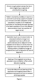
Referring to Figure 1, in one embodiment, a chronic
cough patient may sense that he or she is beginning an
episode of unproductive cough. The patient may voluntarily
provide an input to a controller, such as by a push of a
button on a remote controller subsystem which is
operatively coupled to an implantable controller, to
transiently increase the heat of at least a portion of his
or her afferent nervous system, such as a portion of a
vagus nerve. The controller (such as a microcontroller or
processor) may be configured to deliver energy to an
applicator (such as a cuff or coil positioned around or
adjacent to the targeted nerve tissue) to mildly heat the
targeted nerve tissue and maintain the heating within a
predefined range of temperatures (such as between about 42
and about 45 degrees F). Heating of the targeted nerve
tissue provides a neuroinhibition effect which reduces
coughing in the patient. After a predetermined period of
time or amount of power applied, such as by way of non-
limiting example, 10-100 sec and 100 to 2000 mW, the
controller may be configured to discontinue or decrease the
heating of the targeted tissue.
Referring to Figure 2, a suitable heat delivery system
comprises one or more applicators (A) configured to provide
heat output to the targeted tissue structures. The heat
may be generated within the applicator (A) structure
itself. The one or more delivery segments (DS) serve to
transport, or guide, electricity to the applicator (A). In
an embodiment wherein the heat is generated within the
applicator (A), the delivery segment (DS) may simply
24
CA 02940248 2016-08-19
WO 2015/127401
PCT/US2015/017164
comprise an electrical connector to provide power to the
heat source and/or other components which may be located
distal to, or remote from, the housing (H). The one or
more housings (H) preferably are configured to serve power
to the heat source and operate other electronic circuitry,
including, for example, telemetry, communication, control
and charging subsystems. External programmer and/or
controller (P/C) devices may be configured to be
operatively coupled to the housing (H) from outside of the
patient via a communications link (CL), which may be
configured to facilitate wireless communication or
telemetry, such as via transcutaneous inductive coil
configurations, between the programmer and/or controller
(P/C) devices and the housing (H). The programmer and/or
controller (P/C) devices may comprise input/output (I/O)
hardware and software, memory, programming interfaces, and
the like, and may be at least partially operated by a
microcontroller or processor (CPU), which may be housed
within a personal computing system which may be a stand-
alone system, or be configured to be operatively coupled to
other computing or storage systems. In a further
embodiment, the applicator may contain a temperature
sensor, such as a resistance temperature detector (RTD),
thermocouple, or thermistor, etc. to provide feedback to
the processor in the housing to assure that the tissue
temperature is controlled, as is discussed in further
detail herein.
The Applicator A may consist of a polymer tube that
effectively surrounds the target tissue, such as a nerve.
This tube may further be configured to be surrounded by a
flexible resistive heating element, which may be, in turn
surrounded by another layer of polymer that may serve as an
CA 02940248 2016-08-19
WO 2015/127401
PCT/US2015/017164
insulating layer to reduce the rate of dissipation of the
heat to the surrounding tissue.
The Applicator may be made to fit the target tissue
snugly in order to more directly and efficiently deliver
heat. By way of non-limiting example, a nerve cuff may be
configured to provide an inner diameter that surrounds the
Vagus nerve of a patient, and is between 80-150% of the
effective diameter of the target nerve.
Figure 3 depicts an embodiment of the present
invention, wherein the Target Tissue 1 is surrounded by a
Applicator A that forms a heater cuff Applicator 2. The
Cuff forms a tube with inner diameter as close as possible
to the diameter of the nerve without being substantially
smaller. The cuff should circumferentially enclose the
nerve as completely as possible. The cuff should either be
flexible enough to open and allow placement over the nerve,
such as if it were made of all elastic polymers with only
thin layers of relatively flexible metals or be configured
to utilize braided cables composed of thin wire for the
heating element(s), or have some means of opening to place
on nerve, such as with a hinge or a small segment of
flexible material. Cuff 2 comprises Inner Layer 2a which
is preferably thin, flexible and heat conductive.
A few possible materials for the inner layer are
Silicone, Urethane, Polyimide. Specific examples of such
low durometer, unrestricted grade implantable materials are
MED-4714 or MED4-4420 from NuSil, which have a Shore A
durometer of about 16, while that of natural latex is
nominally about 25. They also have a thermal conductivity
of about 0.82Wm-1K-1, and a thermal diffusivity, a,of about
0.22mm2s-1. This is about 50% greater than that of most
26
CA 02940248 2016-08-19
WO 2015/127401
PCT/US2015/017164
tissues, which has a thermal diffusivity approximately
equal to that of water, a=0.14mm2s-2. Surrounding the inner
layer may be a Heating Element 3. Heating Element 3 may be
configured to be as thin and flexible as possible while
maintaining its mechanical and heat production integrity.
It could either be flexible or segmented to allow placement
on the nerve. At least two electrical connections, shown
as Heater Wire 6, may be utilized to power Heating Element
3. If variations in heating pattern are desired, Heating
Element 3 may be separated into segments which may be
controlled independently. Such segments of Heating Element
3 maybe wired independently or with a common ground (return
lead). Heating Element 3 may be made of anything that
would convert electricity to heat, the simplest of these
materials being resistive metals. Example materials for the
heating element are nichrome, kanthal, cupronickel, and
Inconel. These metals have the benefit of being relatively
flexible. Alternately, a Heating Element may be configured
to utilize braided cables composed of thin wires of the
abovementioned metals. Alternately, a Heating Element may
be produced using a polymer doped with electrically
conductive powder or particulates resulting in a flexible
conductor, such as Metal Rubber, which is produced by
NanoSonics, Inc. Alternately, a polymer-coated metallic
resistive heating Element, such as Silicone Rubber Heaters,
Polymer Thick Film Heaters, UltraFlex and Kapton Heaters,
available from therm Heating Elements, LLC may be
utilized. These heaters are capable of producing between
0.2 - 10W/cm2, and range in thickness from 25m - 1.6mm.
Alternately, smaller segments of more rigid ceramic heating
elements can be used, such as, but not limited to,
27
CA 02940248 2016-08-19
WO 2015/127401
PCT/US2015/017164
molybdenum disulfide, barium titanate and lead titanate.
These segments may be electrically connected to each other
or to the power source individually with highly conductive
wire. Alternately, a single or array of Peltier elements
may be used to heat the target tissue. A Peltier device
may be configured to move heat from one side to the other
when an electrical current is applied, and are capable of
10-15% Carnot efficiencies. This may be used to draw heat
from the outside layer of the cuff to the inside of the
cuff. This may also be used in reverse to cool the nerve.
Alternately, a Peltier device may also be used in
conjunction with a heating element to effectively
neutralize any heating or cooling that would be applied to
the surrounding tissue.
Some heating elements will change in resistance as
their temperature changes. If this change is predictable
and large enough to be measured effectively this change can
be used as feedback in a closed loop control. If the
resistance change is not sufficient or predictable then a
temperature sensor, such as Temperature Sensor 5 may be
configured to monitor the temperature of or adjacent to
Target Tissue. Examples of possible temperature sensors are
thermocouples, thermistors, and thermopiles. Temperature
Sensor 5 would preferably be placed as close to the nerve
as possible. Alternately, the system may be configured to
monitor temperature in multiple locations within the cuff
to be sure that the temperature is consistent over the area
to be heated. Alternatively multiple sensors and
independent heating elements can be used to provide a
desired temperature profile in different areas of the
nerve. Temperature sensors may also be placed in the outer
layers of the cuff to monitor the temperature of the tissue
28
CA 02940248 2016-08-19
WO 2015/127401
PCT/US2015/017164
outside the cuff. Each temperature sensor may be connected
to the control unit via two electrically insulated
conductive wires, such as Temperature Sensor Wires 7, or in
an arrangement with a common return wire. Examples of
temperature sensors that may be used include but are not
limited to a bimetallic sensor or switch, a fluid expansion
sensor or switch, a thermocouple, a thermistor, a
Resistance Temperature Detector, and an infrared pyrometer.
These may be deployed independently, or in combination.
Multiple sensors may be employed, either redundantly, or in
combination.
In configurations where bimetallic or fluid expansion
switches are used, they may be integrated in to an
interlock circuit that carries the therapeutic current, or
as binary sensors that indicate that the sensed temperature
is above, below, or within the desired range. Dual switch
sensors may be deployed in "normally-open" and "normally-
closed" pairs, either in series or in parallel, to provide
for a sensing range, the overlap of them forming the sensor
deadband within which the current is allowed to flow to the
resistive heater in the applicator.
In the case of the pyrometer, an optical fiber may be
used to conduct the sensed light from the tissue to a
detector within the housing of the controller (not shown
for simplicity). Such a fiber would need to be
transmissive in and around the lOpm wavelength region, as
that corresponds to the blackbody radiation at the
temperatures of interest. Chalcochinide glasses and hollow
waveguides are well suited to this application. Similarly,
the detector must be responsive in the same spectral range
noted above. In an alternate configuration, the detector
29
CA 02940248 2016-08-19
WO 2015/127401
PCT/US2015/017164
may be placed within Applicator (cuff) and the resultant
electrical signals transmitted to the controller.
The Heating Element 3 and Temperature Sensor 7 may be
configured to be at least partially encapsulated by
Insulation 4 in order to electrically isolate them from
tissue and to shield them from direct exposure to body
fluids or ingrowth. This material may also serve to hold or
reflect the heat back into the nerve so the surrounding
tissue is heated as little as possible. Preferably the
outer insulating layer of the cuff would have a low thermal
conductivity but be as thin as flexible as possible, as was
described elsewhere herein. Delivery Segment 10 is
equivalent to that described elsewhere herein and in the
referenced material as Delivery Segment DS, or Delivery
Segments DSx. Likewise, Cuff cuff is equivalent to
Applicator A.
Another embodiment may include a single or multiple
Electroneurographic (ENG) nerve recoding electrode(s),
shown as elements 8 and 9 in Figure 3, in the Applicator
(cuff) to sense and/or measure nerve electrical activity
and to sense and/or measure any changes in nerve behavior
as a result of the heating. This signal may be used as
feedback for the controller. ENG recording is well
documented in Methods for neural ensemble recordings by M.
Nicolelis (2008, CRC Press, vol. 2), and Implanted Neural
Interfaces: Biochallenges and Engineered Solutions, by W.
Grille, et al (2009, doi: 10.1146/annurev-bioeng-061008-
124927), and Selective Recording of the Canine Hypoglossal
Nerve Using a Multicontact Flat Interface Nerve Electrode,
by P. Yoo, et al. (2005, doi: 10.1109/TBME.2005.851482),
and Neural Prostheses for Restoration of Sensory and Motor
Function, edited by J. Chapin, et al (2001, ISBN:978-0-
CA 02940248 2016-08-19
WO 2015/127401
PCT/US2015/017164
8493-2225-9),which are incorporated herein in their
entirety.
In an alternate embodiment, ENG measurements may be
made during periods when the heating element is inactive to
eliminate it as a source of noise, such as may be the case
for alternating current configurations. The delay between
such heating and ENG measurement may be substantially
instantaneous, and measurements be recorded for as long as
9ms, 35ms, and 78ms after the cessation of energy to the
heater and substantially not affect the aggregate tissue
temperature of lmm, 2mm, and 3mm diameter target
structures, respectively. This can be appreciated by
considering that the e-2 thermal relaxation time, Tr, of a
cylinder is approximately equal to d2/16a, where d is the
diameter and a is the tissue thermal diffusivity as
described above. An ENG electrode may also be made from
the conductive polymers, such as Metal Rubber, albeit with
a nominally greater conductivity than that of the Heating
Elements described herein.
The Applicator may be detachably attached to a control
and power module within Housing H via a Delivery Segment DS
and connector C. This Delivery Segment may be configured
to be as flexible as possible while providing sufficient
protection for the wires. The wires may be covered in an
insulating protective sleeve. Example materials for
constructing the sleeve material are silicone and urethane.
In one embodiment the cuff lead may be fabricated to have
undulations U to allow for maximum flexibility and to
isolate the distal end of the nerve cuff from any movement
along the length of the cuff lead, as described elsewhere
herein.
31
CA 02940248 2016-08-19
WO 2015/127401
PCT/US2015/017164
As described herein, applicators suitable for use with
the present invention may be configured in a variety of
ways. Referring to Figures 4A-4C, a helical applicator
with a spring-like geometry is depicted. Such a
configuration may be configured to readily bend with,
and/or conform to, a targeted tissue structure (N), such as
a nerve, nerve bundle, vessel, or other structure to which
it is temporarily or permanently coupled. Such a
configuration may be coupled to such targeted tissue
structure (N) by "screwing" the structure onto the target,
or onto one or more tissue structures which surround or are
coupled to the target. As shown in the embodiment of
Figure 4A, an electrical cable may be connected to, or be a
contiguous part of, a delivery segment (DS), and separable
from the applicator (A) in that it may be connected to the
applicator via connector (C). Alternately, it may be
affixed to the applicator portion without a connector and
not removable. Both of these embodiments are also
described with respect to the surgical procedure described
herein. Connector (C) may be configured to serve as a
slip-fit sleeve into which both the distal end of Delivery
Segment (DS) and the proximal end of the applicator are
inserted. The term electrical cable is used herein to
describe an electrical wire, or plurality of wires that may
be used to convey electrical power and/or signals to and
from the applicator and/or housing.
Figure 5 shows an exemplary embodiment, wherein
Connector C may comprise a single flexible component made
of a polymer material to allow it to fit snugly over the
substantially round cross-sectional Delivery Segment DS1,
and Applicator A. These may be electrical leads such as
32
CA 02940248 2016-08-19
WO 2015/127401
PCT/US2015/017164
electric cables and/or wires, and similar mating structures
on the applicator, and/or delivery segment, and/or housing
to create a substantially water-tight seal, shown as SEAL1
& SEAL2, that substantially prevents cells, tissues,
fluids, and/or other biological materials from entering the
Electrical Interface 0-INT.
A Delivery Segment (DS) may also be configured to
include Undulations (U) in order to accommodate possible
motion and/or stretching/constricting of the target
tissues, or the tissues surrounding the target tissues, and
minimize the mechanical load (or "strain") transmitted to
the applicator from the delivery segment and vice versa..
Undulations (U) may be pulled straight during tissue
extension and/or stretching. Alternately, Undulations (U)
may be integral to the applicators itself, or it may be a
part of the Delivery Segments (DS) supplying the applicator
(A). The Undulations (U) may be configured of a succession
of waves, or bends in the waveguide, or be coils, or other
such shapes. Figure 6A-6D illustrate a few of these
different configurations in which Undulations U are
configured to create a strain relief section of Delivery
Segment DS prior to its connection to Applicator A via
Connector C. Figure 6A illustrates a Serpentine section of
Undulations U for creating a strain relief section within
Delivery Segment DS and/or Applicator A. Figure 6B
illustrates a helical section of Undulations U for creating
a strain relief section within Delivery Segment DS and/or
Applicator A. Figure 6C illustrates a Spiral section of
Undulations U for creating a strain relief section within
Delivery Segment DS and/or Applicator A. Figure 6D
illustrates a Bowtie section of Undulations U for creating
33
CA 02940248 2016-08-19
WO 2015/127401
PCT/US2015/017164
a strain relief section within Delivery Segment DS and/or
Applicator A. Target Tissue resides within Applicator in
these exemplary embodiments, but other configurations, as
have been described elsewhere herein, are also within the
scope of the present invention.
Figure 7 shows an alternate embodiment, wherein
Applicator A may be configured such that it is oriented at
an angle relative the Delivery Segment DS, and not normal
to it as was illustrated in the earlier exemplary
embodiments. Such an angle might be required, for example,
in order to accommodate anatomical limitations, such as the
target tissue residing in a crevice or pocket, as may the
case for certain peripheral nerves.
Alternately, DS containing Undulations (U) may be
enclosed in a protective sheath or jacket to allow DS to
stretch and contract without encountering tissue directly.
A rectangular slab applicator may be configured to be
like that of the aforementioned helical-type, or it can
have a permanent Delivery Segment (DS) attached/inlaid.
For example, a slab may be formed such that is a limiting
case of a helical-type applicator, such as is described
elsewhere herein, for explanatory purposes, and to make the
statement that the attributes and certain details of the
aforementioned helical-type applicators are suitable for
this slab-like as well and need not be repeated.
In the embodiment depicted in Figures 8A-8B,
Applicator (A) is fed by Delivery Segment (DS) and the
effectively half-pitch helix is closed along the depicted
edge (E), with closure holes (CH) provided, but not
required, to surround target tissue N.
34
CA 02940248 2016-08-19
WO 2015/127401
PCT/US2015/017164
It should also be understood that the helical-type
applicator described herein may also be utilized as a
straight applicator, such as may be used to provide heat
along a linear structure like a nerve, etc.
The embodiment of Figures 17A-17B, is similar to those
of Figures 3 and 8A-8B, with the additions of a hinge and a
locking feature. Hinge [HINGE] is shown in the open
position as applicator A is placed about target N.
Referring to Figure 17C, the hinge [HINGE] may be
constructed from a pin [PIN] attached to one side of the
cuff [CUFF A] that is rotatably coupled to a split tube
[TUBE] attached to the other side of the cuff [CUFF B].
Alternately, referring to Figure 17D, the
configuration may comprise a living hinge, or a small
flexible section [HINGE] of the cuff between two more rigid
sections [CUFF A] and [CUFF B]. Figures 17A-17B also show
the device in place and secured about target N utilizing
Locking Mechanism [LOCK]. Locking Mechanism [LOCK] may be
any geometry that resists opening once the cuff is closed
around the nerve. This can be a hook like geometry that
relies on a small amount of flexibility in the cuff
structure to bend out of shape while closing or opening as
shown in Figures 17A-17B. Alternately it could require the
operator to move a secondary piece of material that would
prevent the opening of the cuff when not desired.
The embodiment of Figures 18A-18B is similar to that
of Figures 17A-17B, with the addition of a construction
with flexibility that is adequate to apply over the nerve
being used in lieu of the hinge mechanism.
As described herein, an Applicator is placed at, or
adjacent, or nearby a neural target. In certain
embodiments, a cuff is used to engage the target. A cuff
CA 02940248 2016-08-19
WO 2015/127401
PCT/US2015/017164
need not completely surround a nerve. It may surround as
little as 60% and still create a reliable fit in most
instances.
Changes to the output of the heat source may be made
to, for example, the output power, exposure duration,
exposure interval, duty cycle, pulsing scheme, temperature,
energy delivered, etc. It is to be understood that the
term "constant" does not simply imply that there is no
change in the signal or its level, but maintaining its
level within an allowed tolerance. Such a tolerance may be
of the order of 20% on average. However, patient and
other idiosyncrasies may also be need to be accounted and
the tolerance band adjusted on a per patient basis where a
primary and/or secondary therapeutic outcome and/or effect
is monitored to ascertain acceptable tolerance band limits.
As mentioned elsewhere herein, a control band of 2 C may
be sufficient to produce reliable therapy.
Figure 19A illustrates an example of a gross
anatomical location of an implantation / installation
configuration wherein a controller housing (H) is implanted
in the chest, and is operatively coupled (via the delivery
segment DS) to an applicator (A) positioned to stimulate at
least one branch of Vagus Nerve 20. The close-up view of
Figure 19B shows more detail of the exemplary embodiment of
Applicator A and its fixation to Vagus Nerve 20.
Alternately, Applicator A may be deployed at a more distal
nerve branch for the purposes of therapeutic selectivity,
and to ameliorate possible side-effects of collateral
heating of other vagal nerves, both efferent and afferent.
The electrical connections for devices such as these
where the heat source is either embedded within, on, or
36
CA 02940248 2016-08-19
WO 2015/127401
PCT/US2015/017164
located nearby to the applicator, may be integrated into
the applicators described herein. As described earlier
herein, materials like the product sold by NanoSonics, Inc.
under the tradename Metal RubberTM and/or mclO's extensible
inorganic flexible circuit platform may be used to
fabricate an electrical circuit on or within an applicator,
or, alternately, as thermal conduction material.
Alternately, the product sold by DuPont, Inc., under the
tradename PYRALUXO, or other such flexible and electrically
insulating material, like polyimide, may be used to form a
flexible circuit; including one with a copper-clad laminate
for connections. PYRALUX0 in sheet form allows for such a
circuit to be rolled. More flexibility may be afforded by
cutting the circuit material into a shape that contains
only the electrodes and a small surrounding area of
polyimide.
Such circuits then may be encapsulated for electrical
isolation using a conformal coating. A variety of such
conformal insulation coatings are available, including by
way of non-limiting example, parlene (Poly-Para-Xylylene)
and parlene-C (parylene with the addition of one chlorine
group per repeat unit), both of which are chemically and
biologically inert. Silicones and polyurethanes may also
be used, and may be made to comprise the applicator body,
or substrate, itself. The coating material can be applied
by various methods, including brushing, spraying and
dipping. Parylene-C is a bio-accepted coating for stents,
defibrillators, pacemakers and other devices permanently
implanted into the body.
In a particular embodiment, biocompatible and bio-
inert coatings may be used to reduce foreign body
responses, such as that may result in cell growth over or
37
CA 02940248 2016-08-19
WO 2015/127401
PCT/US2015/017164
around an applicator and change the electrical properties
of the system. These coatings may also be made to adhere to
the electrodes and to the interface between the array and
the hermetic packaging that forms the applicator.
By way of non-limiting example, both parylene-C and
poly(ethylene glycol) (PEG, described herein) have been
shown to be biocompatible and may be used as encapsulating
materials for an applicator. Bioinert materials non-
specifically downregulate, or otherwise ameliorate,
biological responses. An example of such a bioinert
material for use in an embodiment of the present invention
is phosphoryl choline, the hydrophilic head group of
phospholipids (lecithin and sphingomyelin), which
predominate in the outer envelope of mammalian cell
membranes. Another such example is Polyethylene oxide
polymers (PEG), which provide some of the properties of
natural mucous membrane surfaces. PEG polymers are highly
hydrophilic, mobile, long chain molecules, which may trap a
large hydration shell. They may enhance resistance to
protein and cell spoliation, and may be applied onto a
variety of material surfaces, such as PDMS, or other such
polymers. An alternate embodiment of a biocompatible and
bioinert material combination for use in practicing the
present invention is phosphoryl choline (PC) copolymer,
which may be coated on a PDMS substrate. Alternately, a
metallic coating, such as gold or platinum, as were
described earlier, may also be used. Such metallic
coatings may be further configured to provide for a
bioinert outer layer formed of self-assembled monolayers
(SAMs) of, for example, D-mannitol-terminated alkanethiols.
Such a SAM may be produced by soaking the intended device
to be coated in 2 mM alkanethiol solution (in ethanol)
38
CA 02940248 2016-08-19
WO 2015/127401
PCT/US2015/017164
overnight at room temperature to allow the SAMs to form
upon it. The device may then be taken out and washed with
absolute ethanol and dried with nitrogen to clean it.
Referring to Figures 9A and 9B, two implantation
configurations featuring housings (H), placed in different
anatomic locations from applicators (A), and operatively
coupled thereto by delivery segments (DS) are depicted.
Referring to Figure 10, a block diagram is depicted
illustrating various components of an example implantable
housing H. In this example, implantable stimulator
includes processor CPU, memory MEM, power supply PS,
telemetry module TM, antenna ANT, and the driving circuitry
DC for a stimulation generator. As used herein, stimulation
refers to heating. The Housing H is coupled to one
Delivery Segments DSx, although it need not be. It may be
a multi-channel device in the sense that it may be
configured to include multiple electrical paths (e.g.,
multiple heat sources and/or electrical leads) that may
deliver different thermal outputs, some of which may have
different local target temperatures and/or thermal loads.
More or less delivery segments may be used in different
implementations, such as, but not limited to, one, two,
five or more electrical leads and associated heat sources
may be provided. The delivery segments may be detachable
from the housing, or be fixed.
Memory (MEM) may store instructions for execution by
Processor CPU, temperature sensor data processed by sensing
circuitry SC, and obtained from sensors both within the
housing, such as battery level, discharge rate, etc., and
those deployed outside of the Housing (H), possibly in
Applicator A, such as temperature sensors, and/or other
39
CA 02940248 2016-08-19
WO 2015/127401
PCT/US2015/017164
information regarding therapy for the patient. Processor
(CPU) may control Driving Circuitry DC to deliver power to
the heat source (not shown) according to a selected one or
more of a plurality of programs or program groups stored in
Memory (MEM). Memory (MEM) may include any electronic data
storage media, such as random access memory (RAM), read-
only memory (ROM), electronically-erasable programmable ROM
(EEPROM), flash memory, etc. Memory (MEM) may store program
instructions that, when executed by Processor (CPU), cause
Processor (CPU) to perform various functions ascribed to
Processor (CPU) and its subsystems, such as dictate pulsing
parameters for the heat source.
Electrical connections may be through Housing H via an
Electrical Feedthrough EFT, such as, by way of non-limiting
example, The SYGNUSO Implantable Contact System from Bal-
SEAL.
In accordance with the techniques described in this
disclosure, information stored in Memory (MEM) may include
information regarding therapy that the patient had
previously received. Storing such information may be useful
for subsequent treatments such that, for example, a
clinician may retrieve the stored information to determine
the therapy applied to the patient during his/her last
visit, in accordance with this disclosure. Processor CPU
may include one or more microprocessors, digital signal
processors (DSPs), application-specific integrated circuits
(ASICs), field-programmable gate arrays (FPGAs), or other
digital logic circuitry. Processor CPU controls operation
of implantable stimulator, e.g., controls stimulation
generator to deliver thermal therapy according to a
selected program or group of programs retrieved from memory
(MEM). For example, processor (CPU) may control Driving
CA 02940248 2016-08-19
WO 2015/127401
PCT/US2015/017164
Circuitry DC to deliver electrical signals, e.g., as
stimulation pulses, with intensities, pulse durations (if
applicable), and rates specified by one or more stimulation
programs. Processor (CPU) may also control Driving
Circuitry (DC) to selectively deliver the stimulation via
subsets of Delivery Segments (DSx), and with stimulation
specified by one or more programs. Different delivery
segments (DSx) may be directed to different target tissue
sites, as was previously described.
Telemetry module (TM) may include, by way of non-
limiting example, a radio frequency (RF) transceiver to
permit bi-directional communication between implantable
stimulator and each of a clinician programmer module and/or
a patient programmer module (generically a clinician or
patient programmer, or "C/P"). A more generic form is
described above in reference to Figure 2 as the
input/output (I/O) aspect of a controller configuration
(P/C). Telemetry module (TM) may include an Antenna (ANT),
of any of a variety of forms. For example, Antenna (ANT)
may be formed by a conductive coil or wire embedded in a
housing associated with medical device. Alternatively,
antenna (ANT) may be mounted on a circuit board carrying
other components of implantable stimulator or take the form
of a circuit trace on the circuit board. In this way,
telemetry module (TM) may permit communication with a
programmer (C/P). Given the energy demands and modest
data-rate requirements, the Telemetry system may be
configured to use inductive coupling to provide both
telemetry communications and power for recharging, although
a separate recharging circuit (RC) is shown in Figure 10
for explanatory purposes. An alternate configuration is
shown in Figure 11.
41
CA 02940248 2016-08-19
WO 2015/127401
PCT/US2015/017164
Referring to Figure 11, a telemetry carrier frequency
of 175kHz aligns with a common ISM band and may use on-off
keying at 4.4kbps to stay well within regulatory limits.
Alternate telemetry modalities are discussed elsewhere
herein. The uplink may be an H-bridge driver across a
resonant tuned coil. The telemetry capacitor, Cl, may be
placed in parallel with a larger recharge capacitor, C2, to
provide a tuning range of 50-130 kHz for optimizing the RF-
power recharge frequency. Due to the large dynamic range of
the tank voltage, the implementation of the switch, Si,
employs a nMOS and pMOS transistor connected in series to
avoid any parasitic leakage. When the switch is OFF, the
gate of pMOS transistor is connected to battery voltage,
VBattery, and the gate of nMOS is at ground. When the switch
is ON, the pMOS gate is at negative battery voltage, -
VBattery, and the nMOS gate is controlled by charge pump
output voltage. The ON resistance of the switch is designed
to be less than 5) to maintain a proper tank quality
factor. A voltage limiter, implemented with a large nMOS
transistor, may be incorporated in the circuit to set the
full wave rectifier output slightly higher than battery
voltage. The output of the rectifier may then charge a
rechargeable battery through a regulator.
Figure 12 relates to an embodiment of the Driving
Circuitry DC, and may be made to a separate integrated
circuit (or "IC"), or application specific integrated
circuit (or "ASIC"), or a combination of them.
The control of the output may be managed locally by a
state-machine, as shown in this non-limiting example, with
parameters passed from the microprocessor. Most of the
design constraints are imposed by the output drive DAC.
42
CA 02940248 2016-08-19
WO 2015/127401
PCT/US2015/017164
First, a stable current is required to reference for the
system. A constant current of 100 nA, generated and
trimmed on chip, is used to drive the reference current
generator, which consists of an R-2Rbased DAC to generate
an 8-bit reference current with a maximum value of 5 pA.
The reference current may then amplified in the current
output stage with the ratio of Ro and Rref, designed as a
maximum value of 40, for example. An on-chip sense-
resistor-based architecture may be used for the current
output stage to eliminate the need to keep output
transistors in saturation, reducing voltage headroom
requirements to improve power efficiency. The architecture
may use thin-film resistors (TFRs) in the output driver
mirroring to enhance matching. To achieve accurate
mirroring, the nodes X and Y may be forced to be the same
by the negative feedback of the amplifier, which results in
the same voltage drop on Ro and Rref. Therefore, the ratio of
output current, Io, and the reference current, 'ref, may be
made equal to the ratio of and Rref and Ro.
The capacitor, C, retains the voltage acquired in the
precharge phase. When the voltage at Node Y is exactly
equal to the earlier voltage at Node X, the stored voltage
on C biases the gate of P2 properly so that it balances
'bias = If, for example, the voltage across Ro is lower than
the original Rref voltage, the gate of P2 is pulled up,
allowing 'bias to pull down on the gate on P1, resulting in
more current to Ro. In the design of this embodiment, charge
injection may be minimized by using a large holding
capacitor of 10pF. The performance may be eventually
limited by resistor matching, leakage, and finite amplifier
gain. With 512 current output stages, the heater drive IC
may drive two outputs for separate heaters (as shown in
43
CA 02940248 2016-08-19
WO 2015/127401
PCT/US2015/017164
Figure 12) with separate sources, each delivering a maximum
current of 51.2mA.
Alternatively, if the maximum back-bias on the thermal
generating element can withstand the drop of the other
element, then the devices can be driven in opposite phases
(one as sinks, one as sources) and the maximum current
exceeds 100mA. The stimulation rate can be tuned from about
0.01Hz to about 1kHz and the pulse or burst duration(s) can
be tuned from about 100s to about 1ms. However, the actual
limitation in the stimulation output pulse-train
characteristic is ultimately set by the energy transfer of
the charge pump, and this generally should be considered
when configuring the therapeutic protocol. Similarly, it
may be made to monitor the amount of energy delivered in a
pulse by controlling one or more of the variable described
above, i.e. the current amplitude, pulse duration, pulse
interval, and the treatment duty cycle.
External programming devices for patient and/or
physician can be used to alter the settings and performance
of the implanted housing. Similarly, the implanted
apparatus may communicate with the external device to
transfer information regarding system status and feedback
information. This may be configured to be a PC-based
system, or a stand-alone system. In either case, the
system generally should communicate with the housing via
the telemetry circuits of Telemetry Module (TM) and Antenna
(ANT). Both patient and physician may utilize
controller/programmers (C/P) to tailor stimulation
parameters such as duration of treatment, voltage or
amplitude, pulse duration, pulse frequency, burst length,
and burst rate, as is appropriate.
44
CA 02940248 2016-08-19
WO 2015/127401
PCT/US2015/017164
Once the communications link (CL) is established, data
transfer between the MMN programmer/controller and the
housing may begin. Examples of such data are:
1. From housing to controller/programmer:
a. Patient usage
b. Battery lifetime
c. Feedback data
i. Device diagnostics (such as target and/or internal
temperature)
2. From controller/programmer to housing:
a. Updated temperature and/or output power level
settings based upon device diagnostics
b. Alterations to pulsing scheme
c. Reconfiguration of embedded circuitry
i. such as field programmable gate array (FPGA),
application specific integrated circuit (ASIC), or
other integrated or embedded circuitry
By way of non-limiting examples, near field
communications, either low power and/or low frequency may
be employed for telemetry. In 2009 (and then updated in
2011), the US FCC dedicated a portion of the EM Frequency
spectrum for the wireless biotelemetry in implantable
systems, known as The Medical Device Radiocommunications
Service (known as "MedRadio" and also known as Medical
Implant Communication Service or "MICS"). Devices
employing such telemetry may be known as "medical
micropower networks" or "MMN" services. The currently
reserved spectra are in the 401 - 406, 413 - 419, 426 -
CA 02940248 2016-08-19
WO 2015/127401
PCT/US2015/017164
432, 438 - 444, and 451 - 457 MHz ranges, and provide for
certain authorized spectral bands.
Interestingly, these frequency bands are used for
other purposes on a primary basis such as Federal
government and private land mobile radios, Federal
government radars, and remote broadcast of radio stations.
It has recently been shown that higher frequency ranges are
also applicable and efficient for telemetry and wireless
power transfer in implantable medical devices. MICS
chipsets are available from MicroSemi, Inc., such as the
Zarlink ZL70321 mixed-band, low-power radio.
An MMN may be made not to interfere or be interfered
with by external fields by means of a magnetic switch in
the implant itself. Such a switch may be only activated
when the MMN programmer/controller is in close proximity to
the implant. This also provides for improved electrical
efficiency due to the restriction of emission only when
triggered by the magnetic switch. Giant Magnetorestrictive
(GMR) devices are available with activation field strengths
of between 5 and 150 Gauss. This is typically referred to
as the magnetic operate point. There is intrinsic
hysteresis in GMR devices, and they also exhibit a magnetic
release point range that is typically about one-half of the
operate point field strength. Thus, a design utilizing a
magnetic field that is close to the operate point will
suffer from sensitivities to the distance between the
housing and the MMN programmer/controller, unless the field
is shaped to accommodate this. Alternately, one may
increase the field strength of the MMN
programmer/controller to provide for reduced sensitivity to
position/distance between it and the implant. In a further
embodiment, the MMN may be made to require a frequency of
46
CA 02940248 2016-08-19
WO 2015/127401
PCT/US2015/017164
the magnetic field to improve the safety profile and
electrical efficiency of the device, making it less
susceptible to errant magnetic exposure. This can be
accomplished by providing a tuned electrical circuit (such
as an L-C or R-C circuit) at the output of the switch.
Alternately, another type of magnetic device may be
employed as a switch. By way of non-limiting example, a
MEMS device may be used. A cantilevered MEMS switch may be
constructed such that one member of the MEMS may be made to
physically contact another aspect of the MEMS by virtue of
its magnetic susceptibility, similar to a miniaturized
magnetic reed switch. The suspended cantilever may be made
to be magnetically susceptible by depositing a
ferromagnetic material (such as, but not limited to Ni, Fe,
Co, NiFe, and NdFeB) atop the end of the supported
cantilever member. Such a device may also be tuned by
virtue of the cantilever length such that it only makes
contact when the oscillations of the cantilever are driven
by an oscillating magnetic field at frequencies beyond the
natural resonance of the cantilever.
Figure 13 illustrates an embodiment, where an external
charging device is mounted onto clothing for simplified use
by a patient, comprising a Mounting Device MOUNTING DEVICE,
which may be selected from the group consisting of, but not
limited to: a vest, a sling, a strap, a shirt, and a pant.
Mounting Device MOUNTING DEVICE further comprising a
Wireless Power Transmission Emission Element EMIT, such as,
but not limited to, a magnetic coil, or electrical current
carrying plate, that is located substantially nearby an
implanted power receiving module, such as is represented by
the illustrative example of Housing H, which is configured
47
CA 02940248 2016-08-19
WO 2015/127401
PCT/US2015/017164
to be operatively coupled to Delivery Segment(s) DS.
Within Housing H, may be a power supply, and controller,
such that the controller activates the heat source by
controlling current thereto. Alternately, the power
receiving module may be located at the applicator (not
shown).
Alternately, a system may be configured to utilize one
or more wireless power transfer inductors/receivers that
are implanted within the body of a patient that are
configured to supply power to the implantable power supply.
There are a variety of different modalities of
inductive coupling and wireless power transfer. For
example, there is non-radiative resonant coupling, such as
is available from Witricity, or the more conventional
inductive (near-field) coupling seen in many consumer
devices. All are considered within the scope of the
present invention. The proposed inductive receiver may be
implanted into a patient for a long period of time. Thus,
the mechanical flexibility of the inductors may need to be
similar to that of human skin or tissue. Polyimide that is
known to be biocompatible was used for a flexible
substrate.
By way of non-limiting example, a planar spiral
inductor may be fabricated using flexible printed circuit
board (FPCB) technologies into a flexible implantable
device. There are many kinds of a planar inductor coils
including, but not limited to; hoop, spiral, meander, and
closed configurations. In order to concentrate a magnetic
flux and field between two inductors, the permeability of
the core material is the most important parameter. As
permeability increases, more magnetic flux and field are
concentrated between two inductors. Ferrite has high
48
CA 02940248 2016-08-19
WO 2015/127401
PCT/US2015/017164
permeability, but is not compatible with microfabrication
technologies, such as evaporation and electroplating.
However, electrodeposition techniques may be employed for
many alloys that have a high permeability. In particular,
Ni (81%) and Fe (19%) composition films combine maximum
permeability, minimum coercive force, minimum anisotropy
field, and maximum mechanical hardness. An exemplary
inductor fabricated using such NiFe material may be
configured to include 200pm width trace line width, 100pm
width trace line space, and have 40 turns, for a resultant
self-inductance of about 25pH in a device comprising a
flexible 24mm square that may be implanted within the
tissue of a patient. The power rate is directly
proportional to the self-inductance.
The radio-frequency protection guidelines (RFPG) in
many countries such as Japan and the USA recommend the
limits of current for contact hazard due to an ungrounded
metallic object under the electromagnetic field in the
frequency range from 10 kHz to 15 MHz. Power transmission
generally requires a carrier frequency no higher than tens
of MHz for effective penetration into the subcutaneous
tissue.
In certain embodiments of the present invention, an
implanted power supply may take the form of, or otherwise
incorporate, a rechargeable micro-battery, and/or
capacitor, and/or super-capacitor to store sufficient
electrical energy to operate the heat source and/or other
circuitry within or associated with the implant when used
along with an external wireless power transfer device.
Exemplary microbatteries, such as the Rechargeable NiMH
button cells available from VARTA, are within the scope of
49
CA 02940248 2016-08-19
WO 2015/127401
PCT/US2015/017164
the present invention. Supercapacitors are also known as
electrochemical capacitors.
Figures 14A and 14B show an alternate embodiment of
the present invention, where a Trocar and Cannula may be
used to deploy an at least partially implantable system for
thermal mediation of the vagus nerve for the control of
cough. Trocar TROCAR may be used to create a tunnel
through tissue between surgical access points that may
correspond to the approximate intended deployment locations
of elements of the present invention, such as applicators
and housings. Cannula CANNULA may be inserted into the
tissue of the patient along with, or after the insertion of
the trocar. The trocar may be removed following insertion
and placement of the cannula to provide an open lumen for
the introduction of system elements. The open lumen of
cannula CANNULA may then provide a means to locate delivery
segment DS along the route between a housing and an
applicator. The ends of delivery segment DS may be covered
by end caps ENDC. End caps ENDC may be further configured
to comprise radio-opaque markings ROPM to enhance the
visibility of the device under fluoroscopic imaging and/or
guidance. End Caps ENDC may provide a watertight seal to
ensure that the electrical contacts of the Delivery Segment
DS, or other system component being implanted, are not
degraded. The cannula may be removed subsequent to the
implantation of delivery segment DS. Subsequently,
delivery segment DS may be connected to an applicator that
is disposed to the target tissue and/or a housing, as have
been described elsewhere herein. In a further embodiment,
the End Caps ENDC, or the Delivery Segment DS itself may be
configured to also include a temporary Tissue Fixation
elements AFx, such as, but not limited to; hook, tines, and
CA 02940248 2016-08-19
WO 2015/127401
PCT/US2015/017164
barbs, that allow the implanted device to reside securely
in its location while awaiting further manipulation and
connection to the remainder of the system.
Figure 15 illustrates an alternate embodiment, similar
to that of Figures 14A&B, further configured to utilize a
barbed Tissue Fixation Element AF that is affixed to End
Cap ENDC. Tissue Fixation Element AF may be a barbed, such
that it will remain substantially in place after insertion
along with Cannula CANNULA, shown in this example as a
hypodermic needle with sharp End SHARP being the leading
end of the device as it is inserted into a tissue of a
patient. The barbed feature(s) of Tissue Fixation Element
AF insert into tissue, substantially disallowing Delivery
Segment DS to be removed. In a still further embodiment,
Tissue Fixation Element AF may be made responsive to an
actuator, such as a trigger mechanism (not shown) such that
it is only in the configuration to affirmatively remain
substantially in place after insertion when activated, thus
providing for the ability to be relocated more easily
during the initial implantation, and utilized in
conjunction with a forward motion of Delivery Segment DS to
free the end from the tissue it has captured. Delivery
Segment DS may be substantially inside the hollow central
lumen of Cannula CANNULA, or substantially slightly forward
of it, as is shown in the illustrative embodiment. As used
herein, cannula also refers to an elongate member, or
delivery conduit. The elongate delivery conduit may be a
cannula. The elongate delivery conduit may be a catheter.
The catheter may be a steerable catheter. The steerable
catheter may be a robotically steerable catheter,
configured to have electromechanical elements induce
51
CA 02940248 2016-08-19
WO 2015/127401
PCT/US2015/017164
steering into the elongate delivery conduit in response to
commands made by an operator with an electronic master
input device that is operatively coupled to the
electromechanical elements. The surgical method of
implantation further may comprise removing the elongate
delivery conduit, leaving the delivery segment in place
between the first anatomical location and the second
anatomical location.
Figure 16 shows an alternate exemplary embodiment of a
system for the treatment of cough via thermal inhibition of
the vagus nerve, comprising elements, such as has been
described herein. Applicator A, a rolled slab-type
applicator that is 12mm wide and 15mm long when unrolled,
such as has been described herein is deployed about the
Target Tissue N, which contains Afferent Nerve(s) 52, of
Lung 42. Applicator A further comprises Sensor SEN1, such
as has been described herein. Electrical energy is
delivered to Applicator A via Delivery Segments DS to
produce heat within Applicator A. Connector C is
configured to operatively couple electrical energy from
Delivery Segments DS to Applicator A, such as has been
described herein. Electrical Lead(s) 88 resident within
Delivery Segments DS may be connected to the Controller
CONT of Housing H via an Electrical Feedthrough EFT, such
as, by way of non-limiting example, The SYGNUSO Implantable
Contact System from Bal-SEAL. Delivery Segments DS further
comprise Undulations U, such as has been described herein.
Delivery Segments DS are further configured to comprise
Signal Wires SW between Sensor SEN1 and the Controller CONT
of Housing H. Delivery Segments DS are operatively coupled
to Housing H via Connector C, such as has been described
herein The Controller CONT shown within Housing H is a
52
CA 02940248 2016-08-19
WO 2015/127401
PCT/US2015/017164
simplification, for clarity, of that described herein.
Sensor(s) SEN1 may be a thermocouple, RID, or other such
thermal sensor as has been described herein. External
clinician programmer module and/or a patient programmer
module C/P may communicate with Controller CONT via
Telemetry module TM via Antenna ANT via Communications Link
CL, such as has been described herein. Power Supply PS,
not shown for clarity, may be wirelessly recharged using
External Charger EC, such as has been described herein.
Furthermore, External Charger EC may be configured to
reside within a Mounting Device MOUNTING DEVICE, such as
has been described herein. Mounting Device MOUNTING DEVICE
may be a vest, as is especially well configured for this
exemplary embodiment. External Charger EC, as well as
External clinician programmer module and/or a patient
programmer module C/P and Mounting Device MOUNTING DEVICE
may be located within the extracorporeal space ESP, while
the rest of the system is implanted and may be located
within the intracorporeal space ISP, such as has been
described herein. External clinician programmer module
and/or a patient programmer module C/P may be configured,
in conjunction with Controller CONT to provide treatment in
response to a user input, such as a button press. As such,
the system may be made to begin treatment on demand, or as
deemed needed by a user.
Although not explicitly identified as such, there have
been published studies aimed at assessing the potential
damage of electrocautery in neurosurgery that effectively
describe the Arrhenius molecular damage model, a known
standard chemical kinetics relation, wherein the damage may
be quantified using a single parameter, Q, a function of
53
CA 02940248 2016-08-19
WO 2015/127401
PCT/US2015/017164
both temperature, T, and time, t, which ranges on the
entire positive real axis and is calculated from an
Arrhenius integral:
C(0)Ea
= in F-1 = 1T Ae [[ RT(t)]1
dt
GTO o
where A is a frequency factor [5-1], T the total heating
time (s), Ea an activation energy barrier [J mole 1], R the
universal gas constant, 8.3143 [J mole-1 K-1], and T the
absolute temperature [K]. The frequency factor, A, and
energy barrier, Eõ are related to the activation enthalpy
and entropy, delta-H* and delta-S*, of the particular
reaction of interest. The characteristic behavior of this
kinetic model is that below a threshold temperature the
rate of damage accumulation is negligible, and it increases
precipitously when this value is exceeded. This behavior is
to be expected from the exponential temperature dependence
of the function. However, it is only linearly time-
dependent. Thus, the temperatures employed in hyperthermia
of neural tissue may need to be well controlled in order to
avoid iatrogenesis due to relatively high rates of damage.
For retinal tissue (akin to peripheral nerves) values for A
and Ea are 1099 s-1 and 6x10⁵ J mole-1, respectively.
Temperatures of about 43 C may be used to inhibit
nerve function in living animals, as we have demonstrated.
This has been shown to be a safe temperature for long
exposure durations, and was not observed by the above-
mentioned studies to cause significant functional and/or
morphological changes. Neural target temperatures ranging
from 39 C to 48 C provide varying efficacy and safety, and
are within the scope of the present invention. Likewise,
54
CA 02940248 2016-08-19
WO 2015/127401
PCT/US2015/017164
controlling those temperatures to within 2 C via means and
methods described elsewhere herein is also within the scope
of the present invention. The complete time-temperature
history, as described above with regard to the Arrhenius
model, is predictive of the amount of damage engendered to
molecular constituent of the tissue, both target tissue and
the surrounding environment. As such, it may be used in an
algorithm for therapeutic dosage.
Published studies by Z. Vujaskovic, et al in Effects
of intraoperative hyperthermia on canine sciatic nerve:
histopathologic and morphometric studies (Int J
Hyperthermia. 1994;10(6):845-55), J. Wondergem, et al in
Effects of Local Hyperthermia on the Motor Function of the
Rat Sciatic Nerve (doi:10.1080/09553008814552561), and J
Carlander, et al in Heat Production, Nerve Function, and
Morphology following Nerve Close Dissection with Surgical
Instruments (doi:10.1007/s00268-012-1471-x) discuss the
Arrhenius-like behavior and the temperature limitations of
electrocautery, each is incorporated in their entirety by
reference.
The
Experimental Confirmation:
A guinea pig was anesthetized with katamine and
xylazine (IM) and laid supine. The ventral neck was shaved
and cleaned. An incision was made in the neck and the
trachea carefully isolated. An incision was made in the
trachea near the carina, and a cannula (breathing tube)
inserted into the trachea. The breathing tube was connected
via a T-connector to a pressure transduced to measure
pressure changes within the breathing tube that
CA 02940248 2016-08-19
WO 2015/127401
PCT/US2015/017164
corresponded to breathing and coughing. The end of the
breathing tube was placed in a chamber filled with
humidified 37 degree C air. The section of the trachea
rostral of the cannula was opened and superfused with 37
degree C Krebs Henseleit buffer. To elicit cough, 100L
aliquots of citric acid was placed on the superfused
trachea. The cough responses were recorded as both changes
in respiratory pressure and visually as exaggerated
abdominal contractions.
Both vagi were carefully dissected clear of adjacent
tissues, including the carotid arteries. Cuffs were placed
around the vagi and the heating elements within the cuffs
were connected to a power supply. Embedded in the cuffs
were thermocouples to record the temperatures within the
cuffs. By varying the current supplied by the power supply
to the cuffs fine control of the temperature within the
cuffs could be accomplished.
As seen in Figure 20, increasing the temperature from
41 degrees C to 44 degrees C showed a diminished cough
response to citric acid applied to the surface of the
trachea. At 44 degrees C the response is completely
inhibited. When the temperature was allowed to return to 37
degrees C the response to citric acid was fully restored.
Thus showing that increasing the temperature of the vagus
nerves to 44 degrees C can inhibit the cough reflex and
that this effect is completely reversible when the
temperature of the nerve returns to normal body
temperature.
Various exemplary embodiments of the invention are
described herein. Reference is made to these examples in a
56
CA 02940248 2016-08-19
WO 2015/127401
PCT/US2015/017164
non-limiting sense. They are provided to illustrate more
broadly applicable aspects of the invention. Various
changes may be made to the invention described and
equivalents may be substituted without departing from the
true spirit and scope of the invention. In addition, many
modifications may be made to adapt a particular situation,
material, composition of matter, process, process act(s) or
step(s) to the objective(s), spirit or scope of the present
invention. Further, as will be appreciated by those with
skill in the art that each of the individual variations
described and illustrated herein has discrete components
and features which may be readily separated from or
combined with the features of any of the other several
embodiments without departing from the scope or spirit of
the present inventions. All such modifications are intended
to be within the scope of claims associated with this
disclosure.
Any of the devices described for carrying out the
subject diagnostic or interventional procedures may be
provided in packaged combination for use in executing such
interventions. These supply "kits" may further include
instructions for use and be packaged in sterile trays or
containers as commonly employed for such purposes.
The invention includes methods that may be performed
using the subject devices. The methods may comprise the act
of providing such a suitable device. Such provision may be
performed by the end user. In other words, the "providing"
act merely requires the end user obtain, access, approach,
position, set-up, activate, power-up or otherwise act to
provide the requisite device in the subject method. Methods
recited herein may be carried out in any order of the
57
CA 02940248 2016-08-19
WO 2015/127401
PCT/US2015/017164
recited events which is logically possible, as well as in
the recited order of events.
Exemplary aspects of the invention, together with
details regarding material selection and manufacture have
been set forth above. As for other details of the present
invention, these may be appreciated in connection with the
above-referenced patents and publications as well as
generally known or appreciated by those with skill in the
art. The same may hold true with respect to method-based
aspects of the invention in terms of additional acts as
commonly or logically employed.
In addition, though the invention has been described
in reference to several examples optionally incorporating
various features, the invention is not to be limited to
that which is described or indicated as contemplated with
respect to each variation of the invention. Various changes
may be made to the invention described and equivalents
(whether recited herein or not included for the sake of
some brevity) may be substituted without departing from the
true spirit and scope of the invention. In addition, where
a range of values is provided, it is understood that every
intervening value, between the upper and lower limit of
that range and any other stated or intervening value in
that stated range, is encompassed within the invention.
Also, it is contemplated that any optional feature of
the inventive variations described may be set forth and
claimed independently, or in combination with any one or
more of the features described herein. Reference to a
singular item, includes the possibility that there are
plural of the same items present. More specifically, as
used herein and in claims associated hereto, the singular
forms "a," "an," "said," and "the" include plural referents
58
CA 02940248 2016-08-19
WO 2015/127401
PCT/US2015/017164
unless the specifically stated otherwise. In other words,
use of the articles allow for "at least one" of the subject
item in the description above as well as claims associated
with this disclosure. It is further noted that such claims
may be drafted to exclude any optional element. As such,
this statement is intended to serve as antecedent basis for
use of such exclusive terminology as "solely," "only" and
the like in connection with the recitation of claim
elements, or use of a "negative" limitation.
Without the use of such exclusive terminology, the
term "comprising" in claims associated with this disclosure
shall allow for the inclusion of any additional element--
irrespective of whether a given number of elements are
enumerated in such claims, or the addition of a feature
could be regarded as transforming the nature of an element
set forth in such claims. Except as specifically defined
herein, all technical and scientific terms used herein are
to be given as broad a commonly understood meaning as
possible while maintaining claim validity.
The breadth of the present invention is not to be limited
to the examples provided and/or the subject specification,
but rather only by the scope of claim language associated
with this disclosure.
59