Note: Descriptions are shown in the official language in which they were submitted.
AMBIENT AIR REFRIGERATION SYSTEM
This application claims the benefit of and priority to U.S. Provisional
Application No.
61/776,631, filed on March 11, 2013.
TECHNICAL FIELD
The inventive technology generally relates to the field of refrigeration. In
particular the
inventive technology is directed to improved methods and apparatus for the
refrigeration of an
enclosed space using external ambient air as a cooling medium.
BACKGROUND
Refrigeration systems that use external ambient air to refrigerate an enclosed
space have
been previously attempted by those in the field with limited success.
Specifically, such
traditional external ambient air refrigeration systems are limited by several
physical, as well as,
design aspects reducing their effectiveness if not rendering them completely
non-functional.
Examples of these limited and in actuality non-functional systems have been
previously
described in US Pat No's. 5239834, 4619114, 4175401, 4178770, 4023947,
4147038, 4272966
and 4244193. For example, as generally described in the above references,
traditional
refrigeration systems may bring external ambient air directly into a
refrigerated space and
exhaust warmer air. Such systems generally require the use of an air-to-air
heat exchanger to
transfer cold outside air to warmer air recirculating from the refrigerated
space without ever
mixing the two air streams. However, there have been no inventions that use
the same
methodology as the invention described below.
In a preferred embodiment, the inventive technology may cool an enclosed space
utilizing, for example, a modular designed duct system that may deliver a
specific volume of
1
Date Recue/Date Received 2020-10-29
CA 02940438 2016-08-22
WO 2014/164892 PCT/US2014/023717
supply air to an enclosed space at a specific temperature differential (TD) in
relation to a desired
set point of the enclosed space. This may be accomplished by mixing cold
outside air and return
air, or even running the return air through a fluid heat transfer chiller coil
that may be cooled to
varying temperatures by outside air utilizing an external chilling unit. The
improvements of
inventive technology overcome the aforementioned systems and address the need
to maintain the
quality and integrity of any product stored in the refrigerated space by not
subjecting it to
extreme temperature swings, thereby maintaining a more constant holding
temperature similar to
the way existing conventional mechanical refrigeration systems ¨ those with a
closed loop
configuration having a condenser and evaporator -- operate, but with a
fraction of the energy
consumption.
It should be noted that the foregoing problems regarding refrigeration systems
and
processes may represent a long-felt need for an effective solution to the
same. While
implementing elements may have been available, actual attempts to meet this
need may have
been lacking to some degree. This may have been due to a failure of those
having ordinary skill
in the art to fully appreciate or understand the nature of the problems and
challenges involved.
As a result of this lack of understanding, attempts to meet these long-felt
needs may have failed
to effectively solve one or more of the problems or challenges here
identified. These attempts
may even have led away from the technical directions taken by the present
inventive technology
and may even result in the achievements of the present inventive technology
being considered to
some degree an unexpected result of the approach taken by some in the field.
DISCLOSURE OF INVENTION(S)
In a preferred embodiment, the inventive technology may be configured to
refrigerate
enclosed spaces that may need to be kept at temperatures colder than normal
living spaces.
Notable examples would include storage spaces such as walk-in coolers, walk-in
freezers, wine
2
CA 02940438 2016-08-22
WO 2014/164892 PCT/US2014/023717
rooms, electronics rooms, food prep rooms, and the like. However, it should be
noted that the
inventive technology is not limited to these examples only and can be scaled
to cool a variety of
refrigerated spaces, large or small. Additionally, in some embodiments the
inventive technology
may be adapted for use in geographic locations where outside temperatures get
at least as cold as
the desired set point of the refrigerated space and a specified temperature
differential below a set
point that may be desired to preserve the quality of any product stored in the
enclosed space.
One objective of the inventive technology may be to reduce the energy
consumption of a
conventional refrigeration system by efficiently refrigerating an enclosed
space utilizing external
ambient air the term being generally interchangeable with outside air. Another
objective of the
inventive technology may be to efficiently refrigerate an enclosed space by
using outside air as
the cooling medium in a manner that addresses the quality of whatever product
might be stored
in the refrigerated space. For example, generally in order for a refrigeration
system to provide
efficient cooling of an enclosed space, it may be required to supply air at a
temperature colder
than the temperature of the enclosure. The difference between the supply air
temperature and the
temperature of the refrigerated space may be referred to as a temperature
differential (TD).
Different TD's may have different effects on the rate of cooling and humidity
at different
temperature levels. Since many products that are stored in refrigerated
spaces, such as food and
beverages, are often sensitive to temperature changes and humidity, it may be
beneficial to
control the TD of the supply air to preserve the quality of the product stored
in the refrigerated
.. space. Also, since different products may have different quality standards,
it may be necessary
for the invention to be adjustable or programmable or both in regards to a TD
setting.
Another objective of the inventive technology may be to simulate a mechanical
refrigeration system, while consuming less energy. Simulating the effects of a
mechanical
3
CA 02940438 2016-08-22
WO 2014/164892 PCT/US2014/023717
refrigeration system may allow the invention to run completely on its own and
still achieve
proper cooling and quality control of a refrigerated space utilizing, for
example, cold outside air.
This inventive technology may also be designed to run in conjunction with an
existing
mechanical refrigeration system, such as a traditional system having an
evaporator and
condenser to cool an enclosed refrigerated space. In certain embodiments, only
the mechanical
refrigeration system may be running at certain times to cool an enclosed
refrigerated space even
while coupled with the inventive technology. At other times, only the
invention may be running
to cool an enclosed refrigerated space. However, in certain environments or
embodiments, a
mechanical refrigeration system may not be necessary at all as the enclosed
refrigerated space
may be sufficiently cooled through operation of said invention alone.
Another objective of the inventive technology may be the application of a
control system.
In some embodiments a sensor and/or controller element may be able to sense
temperature, air
pressure, air flow and humidity in a number of places inside the refrigerated
space, inside the
duct system, and/or externally depending on invention variations and
installation applications.
Such a control system may be a fully automated control, a manual control,
and/or a combination
of the two. In some embodiments, this combination could include a normally
automated control
with manual overrides, or a normally manual operated control, with automated
features. Based
on the control's inputs, the control may dictate when the invention should run
and when for
example, a coupled mechanical refrigeration system should run. For example,
when the
invention is operating, such inputs may dictate the operation of any and all
dampers and/or fan
motor(s) in the air handling container and/or duct system. In variations of
the invention that
include a chilled fluid system, the inputs may dictate the operation of any
and all fan motors,
fluid pumps, and/or mixing valves and the like.
4
CA 02940438 2016-08-22
WO 2014/164892 PCT/US2014/023717
In one embodiment, if the outside air temperature is at or below a
predetermined level
(which may include the desired set point and a sufficient TD), the mechanical
refrigeration
system may turn off and the invention may turn on or, perhaps alter their
output levels
respectively. In another embodiment, if the outside air temperature is at or
above a
predetermined level, the mechanical refrigeration system may turn on and the
invention may turn
off or, perhaps alter their output levels respectively. Through such a control
system, there could
also be built in fail-safes that may turn the mechanical refrigeration system
on, and the invention
off or, perhaps alter their output levels respectively. This control system
may also be
programmed to turn the invention off and turn the mechanical refrigeration
system on, or perhaps
alter their output levels if a maximum allowable humidity level is reached
inside the refrigerated
space, even if the outside temperature is at or below a predetermined level,
in order to maintain a
desired humidity level among other effects. Additionally, such a control
system may include a
feature that may turn off the invention and turn on the mechanical
refrigeration system or,
perhaps alter their output levels if the invention has been running at or near
full capacity for a
predetermined amount of time and the refrigerated space has not reached its
set point, even if the
outside temperature is below the predetermined level, in order to maintain a
more constant
holding temperature. Such a control feature may include a safety monitoring
system that may be
dynamically responsive to any of the elements and/or outputs described herein
to achieve and/or
maintain a desired and/or preset set-point, temperature or TD and the like.
Such a feature may
help prevent product spoilage.
Another feature of such a control system may include a mechanism whereby when
a
coupled mechanical refrigeration system is turned on it may run for a minimum
specified period
of time before shutting off, even if outside air and refrigerated space
humidity are below their
5
CA 02940438 2016-08-22
WO 2014/164892 PCT/US2014/023717
respective predetermined levels to perhaps, make sure that the mechanical
refrigeration system
does not short cycle. There may be other control features to periodically turn
on a coupled
mechanical refrigeration system to a certain or pre-determined level so as to
perhaps to keep the
mechanical system well lubricated, even if outside air and refrigerated space
humidity are below
their respective predetermined levels. This control element may also include a
way to
conveniently indicate to the user what is taking place with the system through
an indicator signal.
Example of such may include LED indicator lights, a digital display read-out,
an LED or LCD
display, and the like or any combination thereof.
Additional embodiments of the inventive technology may include an insulated
air
handling container and duct system. Such a system may circulate air from a
refrigerated space
via one or more return air ducts into the air handling container or box where
it may be
conditioned to a predetermined temperature, humidity, TD or the like. The
system then may
further supply the conditioned air back to the refrigerated space at, for
example, a specific TD
via one or more supply air ducts. In one embodiment of the invention the air
may be conditioned
to a predetermined TD by mixing it directly with, preferably cold outside air
through the use of
dampers and/or a fan in the air handling box. In this embodiment, it may also
be possible to
include an air pressure relief damper on, for example, the return air duct, or
in the wall of the
refrigerated space to make sure the refrigerated space does not get over
pressurized. The control
described above may be used to adjust the return air and outside air dampers
to properly mix the
air to the correct temperature, humidity, TD or the like. Moreover, the
control system could also
be used to dictate when the fan should run and/or how fast the fan should run
if it is a variable-
and/or multi-speed fan.
6
CA 02940438 2016-08-22
WO 2014/164892 PCT/US2014/023717
In another embodiment of the invention, the air may be conditioned to, for
example a
predetermined TD by using a fan to blow or pull the air through, for example a
fluid heat transfer
chiller coil positioned in an air handling container before supplying the air
back to the
refrigerated enclosure. This fluid heat transfer chiller coil may be part of a
circulating loop that
pumps a fluid through an external chiller coil that may have cold outside air
blowing over it to
cool the solution before it flows inside to the coil in the air handling
container where it may
absorb the heat of the recirculating air from the refrigerated space, and then
may be pumped back
outside to reject the heat. There may also be a control element such as the
one described above
that is used to regulate the temperature and flow of the chilled fluid loop in
accordance with the
fan in the air handling box to ensure the air being supplied to the
refrigerated space is, for
example, at or near a predetermined TD. In a preferred embodiment, there may
also be a mixing
valve incorporated in the circulating loop to temper the chilled fluid that is
entering the inside
coil to help maintain, in this case the proper TD.
Additional embodiments may include an air handling container described above,
which
may be configured to have a modular design for ease of installation in many
applications. The air
handling container may be installed inside or outdoors, and either sitting on
the floor or roof,
hanging from the ceiling, or attached to a wall. The air handling box may also
be constructed of
removable and reversible panels to allow the installer to conveniently hook up
the air inlet and
outlet ducts to the top, bottom, ends, or sides of the box. Such modular
design may allow for the
inventive technology to be easily retrofitted, such as in a kit to existing
refrigeration systems and
enclosures to replace and/or supplement traditional mechanical refrigeration
system.
One of the many advantages of the current invention is the ability to use an
air handling
container that can accommodate various heat load requirements of different
sized enclosures
7
CA 02940438 2016-08-22
WO 2014/164892 PCT/US2014/023717
such as a 1/2 - 25 ton enclosures or more, wherein a ton comprises 12,000
BTU's, but larger as
well as smaller enclosures are also contemplated. This variability may be
accomplished perhaps
through a plurality of inventions coupled together, and/or a single and/or
multiple inventions of
variable sizes and/or capacities. This may be accomplished in some embodiments
by using a
variable- and/or multi-speed fan that may adjust to the cooling demand of the
refrigerated
enclosure. With larger spaces such a fan may run faster, and with smaller
spaces the fans may
run slower to make sure the refrigerated enclosure has sufficient cooling. In
some embodiments,
more than one air handling container may be installed to meet larger cooling
demands. In such a
situation, the controllers of each air handling box may be networked together,
independently or
perhaps in series or parallel. In one embodiment, all air handling containers
may be
independently controlled or they may run off a single controller to ensure
that all air handling
boxes are receiving approximately the same or a predetermined input and
output.
Another advantage of the current inventive technology is the ability to
provide a
predetermined level of circulating air within the refrigerated enclosure. Such
predetermined air
circulation may allow the system to deliver approximately equal cooling
throughout the space
similar to the way conventional mechanical refrigeration systems operate. In a
preferred
embodiment, this may be achieved by allowing an existing evaporator fan motor
to continue to
run when the rest of the mechanical refrigeration system turns off and the
invention turns on,
This may also be achieved by using a powerful enough fan in the air handling
box to deliver
enough CFM (cubic feet per minute) of air through an supply air duct(s) to
fully and/or evenly
circulate the air throughout the box. This could also be achieved by replacing
existing evaporator
fan motors with variable speed ECM, or multi-speed motors, if the evaporator
does not already
8
have such motors, and then having these motors run at a lower speed when the
rest of the
mechanical refrigeration system turns off and the invention turns on.
In still other embodiments, the inventive technology may incorporate varying
types and
levels of air filtration. In certain versions of the invention that, for
example, use a direct external
ambient air duct, it may be beneficial to filter any outside air that is
brought into the refrigerated
space in order to keep the air clean inside the refrigerated space and/or
inside the air handling
container. Different levels of air filtration may be utilized depending on the
desired quality of air
inside the refrigerated enclosure and the quality (or lack thereof) of the air
outside. For example,
there could be charcoal filters, HEPA filtration, UV light, and pleated
filters of various sizes and
MERV ratings. Filters may be placed in different locations throughout the
invention's air
mixing box, and/or the outside air duct. Furthermore, in any version of the
invention, filters may
also be placed in the return air duct to filter any recirculating air from the
refrigerated space.
Another embodiment of this invention may allow air recirculation and/or air
replacement
features. These features may allow the invention to periodically turn on with
or without cooling
the refrigerated space in order to keep the air in the refrigerated space from
getting stale or
stagnant. This feature may be combined with certain filter features to help
decrease any airborne
pollutants that may be present or possible in the refrigerated space.
Naturally these and other
aspects, goals and embodiments are discussed in the following specification
and claims.
In accordance with an aspect of the present invention, there is provided an
ambient
refrigeration system for an enclosed refrigerated space comprising: at least
one air handling
container connected to said enclosed refrigerated space through a supply air
duct; at least one
return air duct coupled to separately accept return air from said enclosed
refrigerated space and
configured to provide, at at least some times, air from said enclosed
refrigerated space to said at
9
CA 2940438 2020-03-16
least one air handling container; at least one mechanical refrigeration system
not located inside
said air handling container and responsive to said enclosed refrigerated space
and configured to
operate at at least some times, with air from said enclosed refrigerated space
provided to said at
least one air handling container; at least one external air duct coupled to an
external environment,
and configured to provide, at at least some times, cold external ambient air
to said at least one air
handling container, and thereby to said refrigerated space as a cooling medium
independent from
and without being fed through said at least one mechanical refrigeration
system; at least one
external-return air flow mix regulation controller; at least one external-
return air flow mix
regulator responsive to said external-return air flow mix regulation
controller, coupled with said
return air duct and said external air duct, and capable of regulating air flow
into said air handling
container, said external-return air flow mix regulator comprising: a return
air damper responsive
to said external-return air flow mix regulation controller; and an external
air damper responsive
to said external-return air flow mix regulation controller; wherein said
supply air duct is capable
of directing supply air into said enclosed refrigerated space, and wherein
said mix regulation
controller controls a quantity of said cold external ambient air drawn into
said air handling
container through said external air duct and controls a quantity of said
refrigerated air drawn into
said air handling container through said return air duct.
BRIEF DESCRIPTION OF DRAWINGS
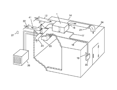
Figure 1: is a perspective view of an air handling container and accompanying
elements in one
embodiment thereof;
Figure 2: is an example of an air handling container and accompanying elements
coupled with
an enclosed refrigerated space in one embodiment thereof;
9a
CA 2940438 2020-03-16
CA 02940438 2016-08-22
WO 2014/164892 PCT/US2014/023717
Figure 3: is a schematic diagram detailing potential air flow routes and
element positions
through an air handling container in one embodiment thereof: and
Figure 4: is a perspective view of an air handling container coupled with an
external chilling
unit in one embodiment thereof.
Figure 5: is a perspective view of an alternative air handling container
having a separate exhaust
duct coupled with an enclosed refrigerated space in one embodiment thereof.
MODE(S) FOR CARRYING OUT THE INVENTION(S)
The present invention includes a variety of aspects, which may be combined in
different
ways. The following descriptions are provided to list elements and describe
some of the
embodiments of the present invention. These elements are listed with initial
embodiments,
however it should be understood that they may be combined in any manner and in
any number to
create additional embodiments. The variously described examples and preferred
embodiments
should not be construed to limit the present invention to only the explicitly
described systems,
techniques, and applications. Further, this description should be understood
to support and
encompass descriptions and claims of all the various embodiments, systems,
techniques,
methods. devices, and applications with any number of the disclosed elements,
with each
element alone, and also with any and all various permutations and combinations
of all elements
in this or any subsequent application.
As shown generally in Figures 1-2, one preferred embodiment of the current
inventive
technology may include an ambient air refrigeration system. In this preferred
embodiment, the
air handling container (1 ) may have an outer shell which may be constructed
of various materials
such as sheet metal, or plastic. or any other appropriate material sufficient
to withstand the
CA 02940438 2016-08-22
WO 2014/164892 PCT/US2014/023717
demands of the invention in its given application. The air handling
container's shell may also
include a layer of insulation (2) to perhaps prevent heat gain on the air
inside the box and/or
prevent condensation outside the box. Various forms of insulation (2) maybe
contemplated such
as foam board insulation or fibrous insulation or any other form of insulation
suitable to fit the
needs of the invention in its given application, or any combination of such
insulators. The
insulation may be placed inside the air handling container (1) as depicted,
but it may also be
possible to insulate the outside of air handling container (1). Such
insulation may be formed of a
mesh internally positioned within an air handling container's (1) wall, such
as an internal cavity.
Again referring to Figure 1, in a preferred embodiment the air handling
container (1) may
be coupled to at least one return air duct (1) and maybe be further coupled to
an enclosed
refrigerated space (14). In addition, the air handling container (1) may also
be coupled to at least
one external air duct (12) that may be further coupled to an enclosed
refrigerated space (14). It
should be noted that such couplings may form fluidically coupled joints
allowing for the free
flow of air among the various described element. As noted in Figure 1, the air
handling container
(1) may have an existing mechanical refrigeration system that is responsive to
said enclosed
refrigerated space. In this embodiment this mechanical refrigeration system is
initially described
as an externally positioned mechanical condenser (26) responsive to a
mechanical evaporator
(25) positioned within the enclosed refrigerated space (14).
Again referring to figure 1, air flow may be regulated in and out of said air
handling
container (1) by at least one air flow regulator which may be coupled with
said return air duct
(11) and/or said external air duct (12). In a preferred embodiment, this air
flow regulator may
include one or more dampers. As shown in Figure 1, a return air damper (3)
external air damper
(4) may be bracketed over the opening of said return air duct (11) and
external air duct (12) in
11
CA 02940438 2016-08-22
WO 2014/164892 PCT/US2014/023717
the air handling container (1) respectively. These dampers may be responsive
to a damper
actuator motor (5), which in this case is positioned outside the air handling
container (1). In a
preferred embodiment, this return air damper (3) as well as external air
damper (4) may be
modulated so as to allow a desired quantity of return and/or external ambient
air into the air
handling container (1). These dampers may work in conjunction, or
independently. In some
embodiments the dampers are activated proportionally such that when one is
opened the other
may be closed to an equal degree. In further embodiments such activation may
be accomplished
through the dynamic, or continuous modulation of a return air damper (3) and
external air
damper (4). In a preferred embodiment, one or more damper actuator motors (5)
may be
responsive to a sensor, such as a supply air sensor (13) and/or an external
air sensor (27) and/or
controller element (20) and may automatically be adjusted to obtain a desired
temperature,
pressure, air flow, TD and/or humidity for example.
Again referring to Figures 1-3, in a preferred embodiment a quantity of
external ambient
air drawn may be into the air handling container (1) through said external air
duct (12). In
addition, a quantity of refrigerated, or return air may be drawn into the air
handling container (1)
through a return air duct (11) such that both quantities are mixed forming a
quantity of
conditioned air. Such conditioned air may have a target temperature, pressure,
air flow, TD
and/or humidity for example. Again as shown in Figure 1, in one embodiment
these quantities of
external ambient and refrigerated or return air may be drawn into the air
handling container (1)
through the action of an air displacement element (6), such as a fan or other
like device.
Again demonstrated in Figures 1-3, this conditioned air may be directed into a
supply air
duct aperture (7) and into a supply air duct (15), again perhaps through the
action of an air
displacement element (6). This conditioned or supply air may then be
redirected into said
12
CA 02940438 2016-08-22
WO 2014/164892 PCT/US2014/023717
enclosed refrigerated space through said supply air duct (15). This air draw
and redirection
through the action of an air displacement element (6) may, in a preferred
embodiment be
accomplished by a fan element. Naturally, a variety of different style fans
can be used in
conjunction with the air handling container (1).
such as an inducer, blower, air-over fan, belt driven fan, squirrel cage fan,
or in line duct fan and
the like. Such fan element may be a variable speed fan or a single speed fan
or a multiple speed
fan and may be responsive to a sensor (13. 27) and/or controller element (20)
described above to
ensure supply air is delivered to the refrigerated space.
As noted previously, as shown in figure 1, the air handling container (1) may
include a
.. space for filters elements accessed through one or more filter access panel
(9). These filters may
be in different locations throughout the box. For example, there may be a
space for a pre-filter
(10) positioned before air enters the air handling container (1), as well as a
secondary filter (8)
positioned before air enters the air handling container (1) into a supply air
duct (15). It should be
noted however, there may also be filtration elements outside the building
before any air enters
the outside air inlet duct. Note that the inlets and/or outlets may be located
in a plurality of
locations such as any variation of ends, sides, top, or bottom for ease of
installation purposes.
Aging referring to Figures 2-3, additional embodiments may include an air
handling
container (1) with one or more inlet air taps (16a) and/or outlet air taps
(16b). As specifically
demonstrated in Figure 3, additional embodiments may include an air handling
container (1) with
one or more air inlet ports (28) air outlet ports (29). There may also be an
additional exhaust duct
(41) that may be coupled with a return air duct (11) with one or more back
draft dampers (21) as
well as perhaps an exhaust air back draft damper (22) coordinated with the
return air duct to
perhaps relieve excess pressure from the enclosed refrigerated space (14),
without letting air in.
13
CA 02940438 2016-08-22
WO 2014/164892 PCT/US2014/023717
Additional embodiments may include an exhaust duct (41) coupled directly with
the enclosed
refrigerated space (14). This exhaust may also have one or more back draft
damper (21) as well
as perhaps an exhaust duct fan (40) to draw return air out of the enclosed
refrigerated space (14),
for example to prevent excess humidity and or pressure within the enclosure.
As can also be seen
in Figure 1, both the return air duct (11), external air duct (12) and supply
air ducts (15) may also
be coupled with back draft dampers (21) to prevent a back-flow of air.
Moreover, such ducts may
also be coupled with register element (23,24) to ensure even distribution of
air flow as well as
possibly providing additional filtration points.
Figure 3 provides a schematic/plan view of the air handling container (1) from
Figures 1
.. and 2 in one alternative embodiment. It demonstrates the air handling
container (1) insulated
walls with reversible external air (4) and return air inlet dampers (2), with
their respective
individual actuators (5). It also demonstrates an exemplary filter space (6)
that may be placed in
front of a fan element that forces the conditioned air through the supply air
duct (15) to be
delivered, for example to the refrigerated space. Figure 3 also illustrates
the locations of various
air inlets and outlets that may be available with the modular design.
Additionally, there may be
filter access panels (9) as well as a depiction of where the damper actuators
and linkages, may be
positioned if they are installed, for example, inside the air handling
container (1) instead of
outside.
As shown in Figure 4, one possible embodiment of the invention may include an
external
ambient air chilled fluid coil refrigeration system. In this embodiment, an
air handling container
(1) may be coupled to at least one return air duct (1) and maybe be further
coupled to an
enclosed refrigerated space (14). In addition, the air handling container (1)
may also be coupled
to at least one external air duct (12) that may be further coupled to an
enclosed refrigerated space
14
CA 02940438 2016-08-22
WO 2014/164892 PCT/US2014/023717
(14). It should be noted that such couplings may form fluidically coupled
joints allowing for the
free flow of air among the various described element. In this embodiment, at
least one fluid heat
transfer chiller coil (31) may be internally positioned within the air
handling container (1) such
that air drawn into the chamber to be mixed may pass through the coil and be
subsequently
cooled, perhaps to a desired TD.
As shown in Figure 4, this embodiment may further include at least one fluid
mix valve
(32) fluidically coupled with the fluid heat transfer chiller coil (31). This
coil may be part of a
closed loop system being coupled to an external chilling unit (33). This
external chilling unit
may include at least one warm fluid return line (39) and at least one cold
fluid supply line (38)
coupled with a fluid reservoir (35) having a quantity of cooling fluid, such
as a mixture of water
and glycerol. This cooling fluid may be pumped into an external chiller coil
(37) that is
fluidically coupled with said fluid reservoir (35) through to a cooling fluid
pump (34). This
cooling fluid may be cooled by the application of ambient external air,
perhaps through at least
one external air regulator (36), such as a fan element positioned so as to
transmit external
ambient air onto said external chiller coil (37).
Again, referring to Figure 4, this cooling fluid may be transmitted back into
Internal fluid
heat transfer chiller coil (31) where at least one air flow regulator (42)
and/or an air displacement
element (6) coupled with said air handling container (1) may regulate air flow
from said return
air duct across said fluid heat transfer chiller coil forming a quantity of
conditioned air. Similar
to above, this conditioned air may be redirected to a supply air duct (7) and
into said enclosed
refrigerated space (14).
While the invention has been described in connection with a preferred
embodiment, it is
not intended to limit the scope of the invention to the particular form set
forth, but on the
CA 02940438 2016-08-22
WO 2014/164892 PCT/US2014/023717
contrary, it is intended to cover such alternatives, modifications, and
equivalents as may be
included within the spirit and scope of the invention as defined by the
statements of invention.
As can be easily understood from the foregoing, the basic concepts of the
present
invention may be embodied in a variety of ways. It involves both external
ambient air
refrigeration techniques as well as devices to accomplish the appropriate
external ambient air
refrigeration. In this application, the external ambient air refrigeration
techniques are disclosed
as part of the results shown to be achieved by the various devices described
and as steps which
are inherent to utilization. They are simply the natural result of utilizing
the devices as intended
and described. In addition, while some devices are disclosed, it should be
understood that these
not only accomplish certain methods but also can be varied in a number of
ways. Importantly, as
to all of the foregoing, all of these facets should be understood to be
encompassed by this
disclosure.
The discussion included in this application is intended to serve as a basic
description.
The reader should be aware that the specific discussion may not explicitly
describe all
.. embodiments possible; many alternatives are implicit. It also may not fully
explain the generic
nature of the invention and may not explicitly show how each feature or
element can actually be
representative of a broader function or of a great variety of alternative or
equivalent elements.
Again, these are implicitly included in this disclosure. Where the invention
is described in
device-oriented terminology, each element of the device implicitly performs a
function.
Apparatus claims may not only be included for the device described, but also
method or process
claims may be included to address the functions the invention and each element
peiforms.
Neither the description nor the terminology is intended to limit the scope of
the claims that will
be included in any subsequent patent application.
16
CA 02940438 2016-08-22
WO 2014/164892 PCT/US2014/023717
It should also be understood that a variety of changes may be made without
departing
from the essence of the invention. Such changes are also implicitly included
in the description.
They still fall within the scope of this invention. A broad disclosure
encompassing both the
explicit embodiment(s) shown, the great variety of implicit alternative
embodiments, and the
.. broad methods or processes and the like are encompassed by this disclosure
and may be relied
upon when drafting any claims. It should be understood that such language
changes and broader
or more detailed claiming may be accomplished at a later date (such as by any
required deadline)
or in the event the applicant subsequently seeks a patent filing based on this
filing. With this
understanding, the reader should be aware that this disclosure is to be
understood to support any
subsequently filed patent application that may seek examination of as broad a
base of claims as
deemed within the applicant's right and may be designed to yield a patent
covering numerous
aspects of the invention both independently and as an overall system.
Further, each of the various elements of the invention and claims may also be
achieved in
a variety of manners. Additionally, when used or implied, an element is to be
understood as
encompassing individual as well as plural structures that may or may not be
physically
connected. This disclosure should be understood to encompass each such
variation, be it a
variation of an embodiment of any apparatus embodiment, a method or process
embodiment, or
even merely a variation of any element of these. Particularly, it should be
understood that as the
disclosure relates to elements of the invention, the words for each element
may be expressed by
equivalent apparatus terms or method terms -- even if only the function or
result is the same.
Such equivalent, broader, or even more generic terms should be considered to
be encompassed in
the description of each element or action. Such terms can be substituted where
desired to make
explicit the implicitly broad coverage to which this invention is entitled. As
but one example, it
17
should be understood that all actions may be expressed as a means for taking
that action or as an
element which causes that action. Similarly, each physical element disclosed
should be
understood to encompass a disclosure of the action which that physical element
facilitates.
Regarding this last aspect, as but one example, the disclosure of a
"regulator" should be
understood to encompass disclosure of the act of "regulating" -- whether
explicitly discussed or
not -- and, conversely, were there effectively disclosure of the act of
"regulating", such a
disclosure should be understood to encompass disclosure of a "regulator" and
even a "means for
regulating." Such changes and alternative terms are to be understood to be
explicitly included in
the description.
In addition, as to each term used it should be understood that unless its
utilization in this
application is inconsistent with a broadly supporting interpretation, common
dictionary
definitions should be understood as incorporated for each term and all
definitions, alternative
terms, and synonyms such as contained in the Random House Webster's Unabridged
Dictionary,
second edition
18
CA 2940438 2020-03-16
CA 02940438 2016-08-22
WO 2014/164892 PCT/US2014/023717
I. U.S. PATENT DOCUMENTS
Patent Number Kind Code Issue Date Name of Patentee or Applicant
of cited Document
7629141 2009-12-08 Bruce, et al.
5239834 1993-08-31 Travers
4244193 1981-01-03 Haakenson
4178770 1979-12-18 Fox
4175401 1979-11-27 McManus
4023947 1977-05-17 Ferry
4147038 1979-04-03 Hoebing et al.
4272966 1981-06-16 Niemann, et al.
Thus, the applicant(s) should be understood to have support to claim and make
a
statement of invention to at least: i) each of the refrigeration devices as
herein disclosed and
described, ii) the related methods disclosed and described, iii) similar,
equivalent, and even
implicit variations of each of these devices and methods, iv) those
alternative designs which
accomplish each of the functions shown as are disclosed and described, v)
those alternative
designs and methods which accomplish each of the functions shown as are
implicit to
accomplish that which is disclosed and described, vi) each feature, component,
and step shown
as separate and independent inventions, vii) the applications enhanced by the
various systems or
components disclosed, viii) the resulting products produced by such systems or
components, ix)
each system, method, and element shown or described as now applied to any
specific field or
devices mentioned, x) methods and apparatuses substantially as described
hereinbefore and with
reference to any of the accompanying examples, xi) the various combinations
and permutations
of each of the elements disclosed, xii) each potentially dependent claim or
concept as a
dependency on each and every one of the independent claims or concepts
presented, and xiii) all
inventions described herein.
19
CA 02940438 2016-08-22
WO 2014/164892 PCT/US2014/023717
With regard to claims whether now or later presented for examination, it
should be
understood that for practical reasons and so as to avoid great expansion of
the examination
burden, the applicant may at any time present only initial claims or perhaps
only initial claims
with only initial dependencies. The office and any third persons interested in
potential scope of
this or subsequent applications should understand that broader claims may be
presented at a later
date in this case, in a case claiming the benefit of this case, or in any
continuation in spite of any
preliminary amendments, other amendments, claim language, or arguments
presented, thus
throughout the pendency of any case there is no intention to disclaim or
surrender any potential
subject matter. It should be understood that if or when broader claims are
presented, such may
require that any relevant prior art that may have been considered at any prior
time may need to
be re-visited since it is possible that to the extent any amendments, claim
language, or arguments
presented in this or any subsequent application are considered as made to
avoid such prior art,
such reasons may be eliminated by later presented claims or the like. Both the
examiner and any
person otherwise interested in existing or later potential coverage, or
considering if there has at
any time been any possibility of an indication of disclaimer or surrender of
potential coverage,
should be aware that no such surrender or disclaimer is ever intended or ever
exists in this or any
subsequent application. Limitations such as arose in Hakim v. Cannon Avent
Group, PLC, 479
F.3d 1313 (Fed. Cir 2007), or the like are expressly not intended in this or
any subsequent related
matter. In addition. support should be understood to exist to the degree
required under new
matter laws -- including but not limited to European Patent Convention Article
123(2) and
United States Patent Law 35 USC 132 Or other such laws-- to permit the
addition of any of the
various dependencies or other elements presented under one independent claim
or concept as
dependencies or elements under any other independent claim or concept. In
drafting any claims
CA 02940438 2016-08-22
WO 2014/164892 PCT/US2014/023717
at any time whether in this application or in any subsequent application, it
should also be
understood that the applicant has intended to capture as full and broad a
scope of coverage as
legally available. To the extent that insubstantial substitutes are made, to
the extent that the
applicant did not in fact draft any claim so as to literally encompass any
particular embodiment,
and to the extent otherwise applicable, the applicant should not be understood
to have in any way
intended to or actually relinquished such coverage as the applicant simply may
not have been
able to anticipate all eventualities; one skilled in the art, should not be
reasonably expected to
have drafted a claim that would have literally encompassed such alternative
embodiments.
Further, if or when used, the use of the transitional phrase "comprising" is
used to
maintain the "open-end" claims herein, according to traditional claim
interpretation. Thus,
unless the context requires otherwise, it should be understood that the term
"comprise" or
variations such as "comprises" or "comprising", are intended to imply the
inclusion of a stated
element or step or group of elements or steps but not the exclusion of any
other element or step
or group of elements or steps. Such terms should be interpreted in their most
expansive form so
as to afford the applicant the broadest coverage legally permissible. The use
of the phrase, "or
any other claim" is used to provide support for any claim to be dependent on
any other claim,
such as another dependent claim, another independent claim, a previously
listed claim, a
subsequently listed claim, and the like. As one clarifying example, if a claim
were dependent
"on claim 20 or any other claim" or the like, it could be re-drafted as
dependent on claim 1,
claim 15, or even claim 715 (if such were to exist) if desired and still fall
with the disclosure. It
should be understood that this phrase also provides support for any
combination of elements in
the claims and even incorporates any desired proper antecedent basis for
certain claim
combinations such as with combinations of method, apparatus, process, and the
like claims.
21
Furthermore, it should be noted that certain embodiments of the current
invention may
indicate a coupler, or the step of coupling. It should be noted that these may
indicate a direct or
in some cases an indirect connection and/or bring together of disparate or non-
disparate elements
in a functional, non-functional or desired configuration.
In addition and as to computer, controller or sensor aspects and each aspect
amenable to
software, programming or other electronic automation, the applicant(s) should
be understood to
have support to claim and make a statement of invention to at least: xvi)
processes performed
with the aid of or on a computer as described throughout the above discussion,
xv) a
programmable apparatus as described throughout the above discussion, xvi) a
computer readable
memory encoded with data to direct a computer comprising means or elements
which function as
described throughout the above discussion, xvii) a computer configured as
herein disclosed and
described, xviii) individual or combined subroutines and programs as herein
disclosed and
described, xix) the related methods disclosed and described, xx) similar,
equivalent, and even
implicit variations of each of these systems and methods, xxi) those
alternative designs which
accomplish each of the functions shown as are disclosed and described, xxii)
those alternative
designs and methods which accomplish each of the functions shown as are
implicit to
accomplish that which is disclosed and described, xxiii) each feature,
component, and step
shown as separate and independent inventions, and xxiv) the various
combinations and
permutations of each of the above.
22
CA 2940438 2020-03-16