Note: Descriptions are shown in the official language in which they were submitted.
CA 02940484 2016-08-22
WO 2015/134055 PCT/US2014/047931
AUTOMATIC HEADER COUPLING
TECHNICAL FIELD
The present disclosure is generally related to agriculture technology, and,
more
particularly, combine harvesters.
BACKGROUND
Combine harvesters headers are very wide, and are not compatible with
circulation on most roads. The most common method to transport the header from
field
to field is to detach the header from the combine harvester and use a trailer
to transport
the header. Attaching and detaching the header takes time, and the operator
needs to
leave the combine harvester cab several times to complete the operations.
Further,
attaching and detaching the header is often a messy job, with hydraulic
fluids, dust, etc.
involved in causing the grimy conditions.
BRIEF DESCRIPTION OF THE DRAWINGS
Many aspects of the disclosure can be better understood with reference to the
following drawings. The components in the drawings are not necessarily to
scale,
emphasis instead being placed upon clearly illustrating the principles of the
present
disclosure. Moreover, in the drawings, like reference numerals designate
corresponding
parts throughout the several views.
FIG. 1 is a schematic diagram, in partial cutaway view, of an example combine
harvester showing an embodiment of an automatic header coupler system.
FIG. 2 is a schematic diagram in a top front perspective view of an example
combine harvester showing a header with shafts coupled to opposing sides of a
tilt
frame of a feeder house for an embodiment of an automatic header coupler
system.
1
CA 02940484 2016-08-22
WO 2015/134055 PCT/US2014/047931
FIG. 3 is a schematic diagram in overhead front perspective view showing an
embodiment of a combine harvester feeder house assembly for an embodiment of
an
automatic header coupler system.
FIG. 4 is a schematic diagram in front perspective view showing an embodiment
of a combine harvester feeder house assembly for an embodiment of an automatic
header coupler system.
FIG. 5 is a schematic diagram in front, close-up perspective view showing an
example mechanical coupling between a shaft of a header and a dog clutch of an
embodiment of a combine harvester feeder house assembly for an embodiment of
an
automatic header coupler system.
FIG. 6 is a schematic diagram in cut-away, side elevation view a dog clutch of
an
embodiment of a combine harvester feeder house assembly for an embodiment of
an
automatic header coupler system.
FIG. 7 is a schematic diagram in front, close-up perspective view showing a
pivotally-covered quick connect apparatus and ram sub-assembly of an
embodiment of a
combine harvester feeder house assembly initiating hydraulic coupling to a
header in an
embodiment of an automatic header coupler system.
FIG. 8 is a schematic diagram in rear perspective view showing an example
header and shaft for an embodiment of an automatic header coupler system.
FIGS. 9A-9B are block diagrams that illustrate an embodiment of a control
system including a controller for an embodiment of an automatic header coupler
system.
FIG. 10 is a flow diagram that illustrates an example embodiment of an
automatic
header coupler method.
DESCRIPTION OF EXAMPLE EMBODIMENTS
Overview
2
CA 02940484 2016-08-22
WO 2015/134055 PCT/US2014/047931
In one embodiment, a combine harvester feeder house assembly, comprising: a
feeder house comprising an inlet end; a tilt frame surrounding the inlet end
and in pivotal
arrangement relative to the feeder house; a gearbox attached to the tilt
frame; and a first
dog clutch operably coupled to the gearbox.
Detailed Description
Certain embodiments of an automatic header coupler system and method are
disclosed that save time during header attaching and detaching operations for
a
combine harvester, allow for the operator to remain in a cab of the combine
harvester
during such operations in many cases, and provides backwards compatibility for
legacy
attach and detach systems (e.g., old-style headers with U-joint shafts). In
one
embodiment, a drive connection (e.g., for mechanical coupling) is disposed
between a
tilt frame of a feeder house of the combine harvester and a shaft of the
header, the drive
connection comprising a dog clutch that is powered by an electrically or
hydraulically
powered ram sub-assembly. In some embodiments, electrical and/or hydraulic
connections between the tilt frame and the header are achieved using a rapid
or quick
connection assembly (herein, also referred to as a quick connect apparatus).
Hereinafter, electrical and/or hydraulic connections are referred to as simply
hydraulic
connections or the like (e.g., hydraulic coupling, hydraulic coupling
mechanisms, etc.) for
brevity, with the understanding that in some embodiments, both electrical and
hydraulic
connections and/or mechanisms, etc. may be implemented in some embodiments.
The
hydraulic connections are likewise ram-actuated using the same, or in some
embodiments, a different ram sub-assembly. These and/or other features are
described
further below, and enable automatic header coupling (e.g., without any person
having to
physically make the aforementioned connections at the locale of those
connections).
Digressing briefly, since introducing quick attach headers in the 1960s, the
ease
in which headers are attached and detached to and from combine harvesters has
3
CA 02940484 2016-08-22
WO 2015/134055 PCT/US2014/047931
improved by providing a centralized location where the operator may reach all
necessary
levers and drives. For instance, a drive dog clutch requiring a king pin to
install was
located on the left side of the feeder house (or in some cases, both sides),
the
hydraulics on the right side, and the process of locking the header to the
feeder required
four (4) pins (e.g., two (2) on each side). In the 1970s, at least one
manufacturer of
combine harvesters offered a device that enabled locking the header to the
feeder house
and pushing a dog clutch using a single hand lever actuated from the ground.
In many
of today's combine harvesters, the drive U-joints, the lever to lock the
header (e.g., no
more pins), and the fast coupling hydraulic system are on the left side of the
feeder
house, yet the three (3) operations associated with these mechanisms still
need to be
done by hand in what often proves to be a rather dirty and/or generally
uncomfortable
endeavor for the operator (or any other person there to assist the operator).
Indeed, for
larger headers using left and right-side drive connections, the area covered
by the
operator is increased, as is the time consumed in performing these operations.
In
contrast, certain embodiments of an automatic header coupler system, for
reasons that
are to be clear in the description below, save time during the process of
header
attachment and/or removal, including reducing the amount of time the operator
is out of
the cab and/or enabling the operator to avoid some of the less desirable tasks
associated with these operations.
Having summarized certain features of automatic header coupler systems of the
present disclosure, reference will now be made in detail to the description of
the
disclosure as illustrated in the drawings. While the disclosure will be
described in
connection with these drawings, there is no intent to limit it to the
embodiment or
embodiments disclosed herein. For instance, in the description that follows,
one focus is
on a combine harvester having a transverse-rotor design, though it should be
appreciated within the context of the present disclosure that combine
harvesters of other
4
CA 02940484 2016-08-22
WO 2015/134055 PCT/US2014/047931
designs, such as hybrid, conventional, axial, or dual axial, may be used and
hence are
contemplated to be within the scope of the present disclosure. Further,
although the
description identifies or describes specifics of one or more embodiments, such
specifics
are not necessarily part of every embodiment, nor are all various stated
advantages
necessarily associated with a single embodiment or all embodiments. On the
contrary,
the intent is to cover all alternatives, modifications and equivalents
included within the
spirit and scope of the disclosure as defined by the appended claims. Further,
it should
be appreciated in the context of the present disclosure that the claims are
not
necessarily limited to the particular embodiments set out in the description.
Note that references hereinafter made to certain directions, such as, for
example,
"front", "rear", "left" and "right", are made as viewed from the rear of the
combine
harvester looking forwardly.
Referring now to FIG. 1, shown is an example combine harvester 10 in which an
embodiment of an automatic header coupler system may be implemented. It should
be
understood by one having ordinary skill in the art, in the context of the
present
disclosure, that the example combine harvester 10 shown in FIG. 1 is merely
illustrative,
and that other combine configurations may be implemented in some embodiments.
The
example combine harvester 10 is shown in FIG. 1 without a header, and from
front to
back, comprises a feeder house 12 and an operator cab 14, followed by a
processing
compartment that includes a processing apparatus 16. In operation, the combine
harvester 10 includes a harvesting header (shown in FIG. 2, as described
below) at the
front of the machine that cuts crop materials and delivers the cut crop
materials to the
front or inlet end of the feeder house 12. Such crop materials are moved
upwardly and
rearwardly within and beyond the feeder house 12 by a conveyor 18 until
reaching the
processing apparatus 16. In the depicted example, the processing apparatus 16
comprises a single, transverse rotor 20 (e.g., such as that found in a
Gleaner() Super
5
CA 02940484 2016-08-22
WO 2015/134055 PCT/US2014/047931
Series Combine by AGCO), and a rotor cage 22 surrounding the rotor 20. The
rotor
cage 22 comprises well-known foraminous processing members in the form of
threshing
concave assemblies and separator grate assemblies. In the processing apparatus
16,
well-known threshing and separating operations are performed. For instance,
bulkier
stalk and leaf materials are generally retained by the concave assemblies and
the grate
assemblies, and are discharged out from the processing apparatus 16 and
ultimately out
of the rear of the combine harvester 10. Grain (and possibly light chaff)
escapes through
the concave assemblies and the grate assemblies of the processing apparatus
16, and
is discharged onto one or more distribution augers 24, with the resultant
distributed crop
material provided to one or more accelerator rolls 26. The crop material is
propelled
from the accelerator rolls 26, and enters a cleaning system 28 comprising a
shoe
assembly. The shoe assembly comprises a cascade pan, which is impacted by the
crop
material propelled from the accelerator rolls 26, as well as plural stacked
oscillating
sieve assemblies that receive the crop material from the cascade pan and
convey the
crop material rearward. A fan 30 provides air through upper and lower ducts 32
to assist
the oscillating mechanisms of the shoe assembly in conveying the chaff flow to
the rear
of the combine harvester 10. The cleaned grain that drops to the bottom of the
cleaning
system 28 is delivered by an auger that transports the grain to a well-known
elevator
mechanism (not shown), which conveys the grain to a grain bin located at the
top of the
combine harvester 10. Any remaining chaff and partially or unthreshed grain is
recirculated through the processing apparatus 16 via a tailings return auger.
As combine
processing is known to those having ordinary skill in the art, further
discussion of the
same is omitted here for brevity.
FIG. 2 shows a top-down view from a location proximal to the top of the
operator
cab 14 of the combine harvester 10 of FIG. 1. As shown, the feeder house 12
has
secured to it a header 34, shown partially in FIG. 2, which may be removed and
replaced
6
CA 02940484 2016-08-22
WO 2015/134055 PCT/US2014/047931
with other types of headers depending on the application. Although shown as a
draper
style header, other types of headers may be used, such as pickup headers, corn
headers, etc. In one embodiment, the header 34 comprises a cutting portion 36
for
cutting the crops and a transition portion 38 that conveys (e.g., using a
conveyor, such
as a belt or belts, chain and slat configuration, etc.) the cut crops toward a
rear, center
portion 40 of the header 34, as is known. The center portion 40 may comprise a
feeder
auger (not shown) to advance the harvested crop material toward the inlet of
the feeder
house 12, where the conveyor 18 (FIG. 1) conveys the crop material toward the
processing apparatus 16 (FIG. 1).
Evident from FIG. 2 is that header shafts 42 (e.g., left header shaft 42A and
right
header shaft 42B) are operably coupled to a tilt frame 44 of the feeder house
12, and not
directly to the feeder house 12 itself, which is in contrast to today's manner
of
attachment.
Referring now to FIG. 3, shown is an embodiment of automatic header coupler
system comprising a combine harvester feeder house assembly 46 (hereinafter,
also
referred to simply as a feeder house assembly for brevity). It should be
appreciated
within the context of the present disclosure that some embodiments may include
additional components or fewer or different components, and that the example
depicted
in FIG. 3 is merely illustrative of one embodiment among others. The feeder
house
assembly 46 is equipped for automated (and in some embodiments, manual)
mechanical and hydraulic connections between the tilt frame 44 of the feeder
house 12
and the header 34 (FIG. 2). The feeder house assembly 46 comprises the feeder
house
12, which comprises a longitudinal axis 48 and an inlet end 50 where harvested
crop
material enters the combine harvester 10 (FIG. 1) from the header 34. The
feeder
house assembly 46 also comprises the tilt frame 44, which is adjacent the
inlet end 50
and surrounds a front portion of the feeder house 12. The tilt frame 44 is
arranged in
7
CA 02940484 2016-08-22
WO 2015/134055 PCT/US2014/047931
pivotal arrangement (e.g., with the ability to roll relative to the center,
longitudinal axis
48, as denoted by the double arrow symbol) relative to the feeder house 12, as
is
known. In one embodiment, a pivot point 52 and a cylinder (not shown, but
typically at
the top portion of the tilt frame 44) that is coupled between the tilt frame
44 and the
feeder house 12 collectively enable the pivotal capability, though some
embodiments
may locate the pivot point in different and/or additional locations. The
feeder house 12
and the tilt frame 44 that is pivotally attached to the feeder house 12 are
moveable in
upwards and downwards directions due to one or more hydraulic cylinders (not
shown)
located beneath the feeder house 12 and coupled to the frame of the combine
harvester
10, as is known. The upwards and downwards movement of the feeder house 12 and
the tilt frame 44 through attachment to the feeder house 12 enables the header
34 to be
raised and lowered, which enables the operator (through manipulation of
machine
controls via a user interface in the cab 14 (FIG. 1) or elsewhere) to lift a
top lip of the tilt
frame 44 underneath a top edge of the header 34 to commence attachment
operations
of the header 34 to the feeder house 12 (and similarly, the detachment through
lowering
in a reversal of operations). The tilt frame rotation relative to the feeder
house 12
enables alignment of mechanical and hydraulic connections in collaboration
with the
upward and downward and fore and aft movement of the feeder house 12 and
combine
harvester 10, respectively.
The feeder house assembly 46 also comprises a dog clutch 54 that enables a
mechanical connection to the header 34 (FIG. 2), and in one embodiment, a ram
sub-
assembly 56 that enables transverse movement of the dog clutch 54 and a
hydraulic
coupler (obscured from view) to engage corresponding mating features of the
header 34,
as described further below. Also shown is a hingeable dust cover 58, which
pivotally
opens to enable rapid coupling of the hydraulic coupler of the feeder house
assembly 46
to the header 34, while providing protection from the elements (e.g., dust,
dirt, etc.) when
8
CA 02940484 2016-08-22
WO 2015/134055 PCT/US2014/047931
in the closed-position. Importantly, the mechanical coupling mechanisms (e.g.,
the dog
clutch 54) and at least a portion of the hydraulic coupler mechanisms of the
feeder
house assembly 46 move with the tilt frame 44 even when the tilt frame 44 does
not
move in correspondence with the feeder house 12. In contrast, conventional
header
coupling systems comprise movements that are dependent only on the feeder
house
movements.
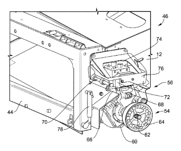
Referring now to FIG. 4, shown is a closer view of the feeder house assembly
46
shown in FIG. 3. It should be appreciated within the context of the present
disclosure
that some embodiments may include additional components or fewer or different
components, and that the example depicted in FIG. 4 is merely illustrative of
one
embodiment among others. For instance, though mechanical and hydraulic
coupling
mechanisms are depicted on the portion of the tilt frame 44 that is on the
left side of the
feeder house 12, some embodiments may use all or part of these components on
the
right side portion of the tilt frame 44, or on both sides, in some
embodiments. The
feeder house assembly 46 comprises the feeder house 12, and the tilt frame 44
as
described above. The feeder house assembly 46 also comprises mechanical and
hydraulic apparatuses pertinent to automated connections to the header 34
(FIG. 2) that
are moveable along all axes with the tilt frame 44. As noted above, the
rotational
movement of the tilt frame 44 is independent of the movement along at least
one axis of
the feeder house 12, the latter lacking machine-independent rotational
movement. The
feeder house assembly 46 comprises, beginning at the lower left side of the
tilt frame 44,
the dog clutch 54. The dog clutch 54 is directly and operably coupled to a
gearbox 60
that is attached (e.g., directly) to the tilt frame 44. The gearbox 60 enables
rotational
motion of a transverse shaft running through the feeder house 12 and directly
(or in
some embodiments, indirectly) coupled to the dog clutch 54. The dog clutch 54
comprises a spline joint 62 that enables mating of the splines with grooves of
a receiving
9
CA 02940484 2016-08-22
WO 2015/134055 PCT/US2014/047931
joint (e.g., U-joint) of a shaft of the header 34. The dog clutch 54 also
comprises
interference members 64 (e.g., twelve (12) shown, though some embodiments may
use
different quantities), which enable an interference fit with the shaft 42
(e.g., 42A, FIG. 2),
which in some embodiments lacks a U-joint, of the header 34. In other words,
the dog
clutch 54 comprises backwards compatibility with older-style headers, as well
as newer-
style headers.
Also shown as part of the feeder house assembly 46 is the ram sub-assembly
56. In one embodiment, the ram sub-assembly 56 comprises a cylinder 66 (e.g.,
partially
obscured from view), a bracket 68 directly coupled to the cylinder 66, and a
linear guide
assembly 70. The bracket 68 is directly coupled to an outer sleeve of the dog
clutch 54,
to a quick connect apparatus 72, and to the cylinder 66, which may be
electrically or
hydraulically powered via an associated actuator (e.g., configured, for
instance in the
case of the cylinder 66, as a valve located on the machine). The cylinder 66
causes
(through the commonly attached bracket 68) transverse movement to both the
quick
connect apparatus 72 and the dog clutch 54 to enable automatic and secure
engagement with hydraulic and mechanical components of the header 34 (FIG. 2),
respectively. The quick connect apparatus 72 is depicted in FIG. 4 as directly
coupled to
(e.g., integrated with, or connected via appropriate conduit) a hydraulic
apparatus 74,
which comprises an actuator (e.g., solenoid). The quick connect apparatus 72
and the
hydraulic apparatus 74 are housed within a frame 76, which has the pivotal
cover 58
(FIG. 3) attached thereto (not shown in FIG. 4). In some embodiments, the
hydraulic
apparatus 74 may be located remotely from the quick connect apparatus 72,
coupled
through one or more conduits (e.g., wiring, tubing, etc.). The quick connect
apparatus
72 is slidably coupled to the linear guide assembly 70. In one embodiment, the
linear
guide assembly 70 comprises cylindrical guide rods (one shown in FIG. 4) that
are
partially surrounded by door-hinge-like structural portions of the quick
connect apparatus
CA 02940484 2016-08-22
WO 2015/134055 PCT/US2014/047931
72 that are attached on one end to the tilt frame 44, enabling a sliding
movement of the
quick connect apparatus 72 in the transverse direction along the guide rods.
In some
embodiments, other configurations may be used in place of the cylindrical
guide rods
(e.g., more rectangular or other geometrical configurations) to enable linear,
transverse
motion of the quick connect apparatus 72 in transverse directions. The quick
connect
apparatus 72 comprises ports that mate with corresponding connection features
of a
hydraulic coupler apparatus on the header 34. Likewise, the dog clutch 54
comprises
features that mate with corresponding features of a shaft of the header 34, as
described
above.
In one example operation, to align the dog clutch 54 with a shaft of the
header 34
(FIG. 2), the feeder house 12 and tilt frame 44 are aligned to the header 34
and
associated shaft (e.g., as controlled from the cab 14 (FIG. 1) of the combine
harvester
10 (FIG. 1)). To achieve the header-to-feeder house mechanical and hydraulic
coupling
connections, the cylinder 66 is actuated (e.g., via direct or indirect control
by a controller,
as prompted by an operator activating the coupling mechanisms from the cab
14),
causing the cylinder 66 to push the bracket 68 outward (e.g., away from the
tilt frame
44). The bracket 68, through its attachment to the dog clutch 54 and the quick
connect
apparatus 72, causes a concomitant outward motion of the dog clutch 54 and the
quick
connect apparatus 72. The quick connect apparatus 72 slides along the rods of
the
linear guide assembly 70. The result of the transverse movement of the dog
clutch 54
and the quick connect apparatus 72 is an automated coupling to a shaft of the
header 34
and to a hydraulic coupler of the header 34.
The feeder house assembly 46 also comprises a table locking cylinder 78
disposed on the left side (though not limited to that location) of the feeder
house 12, and
in particular, attached to the tilt frame 44. The table locking cylinder 78
may be
electrically or hydraulically powered, and actuated by the operator from
within the cab 14
11
CA 02940484 2016-08-22
WO 2015/134055 PCT/US2014/047931
(FIG. 1) of the combine harvester 10 (FIG. 1). The table locking cylinder 78
locks the
table of the feeder house 12, maintaining a tight relationship between the
tilt frame 44
and a mating face of the table (e.g., and hence, maintaining shaft alignments,
regardless
of the terrain).
It should be appreciated within the context of the present disclosure that
variations to the above-described feeder house assembly 46 may also
implemented.
For instance, in one embodiment, the dog clutch 54 and the quick connect
apparatus 72
may be driven in the transverse direction independently (e.g., by separate and
dedicated
cylinders 66, and no bracket 68). In some embodiments, for instance where the
mechanical coupling features of the feeder house assembly 46 are duplicated on
the
right side of the tilt frame 44 in conjunction with the feeder house assembly
46 on the left
side of the tilt frame 44, the dog clutch 54 may be driven by a single
cylinder, similar to
cylinder 66, with no hydraulic coupling needed on the right side and also no
bracket 68
needed.
Attention is now directed to FIG. 5, which shows a portion of the feeder house
assembly 46 of FIG. 4, and certain features of the header 34 to which the
feeder house
assembly 46 is to engage. In particular, the feeder house assembly 46
comprises, from
the bottom-up in FIG. 5, the gearbox 60, the dog clutch 54 coupled to the
gearbox 60,
and the ram sub-assembly 56 comprising the bracket 68, cylinder 66, and linear
guide
assembly 70. Also shown is the header 34, which includes the shaft 42A, and a
header
bracket 80 and quick connectors 82. The quick connectors 82 may carry
hydraulic fluid
and electricity. On the left side of the header bracket 80 looking at FIG. 5,
various
conduit (e.g., wiring, tubing, etc., not shown) may be connected between the
quick
connectors 82 and various known devices requiring hydraulic fluid and
electrical power
on the header 34. Looking at the right side of the bracket 80, the quick
connect 72,
upon outward transverse movement as actuated by the cylinder 66, engages with
12
CA 02940484 2016-08-22
WO 2015/134055 PCT/US2014/047931
suitable mating features of the quick connectors 82. The cylinder 66 also
causes, by
translation of motion through the connected bracket 68, connection between the
dog
clutch 54 and the shaft 42A.
With reference to FIG. 6, shown in cut-away view is the dog clutch 54. The dog
clutch 54 comprises a cup-shaped shield 84, with a wider diameter open face 86
that
engages in a circumferential fit with a smaller diameter shield of the shaft
42 (e.g., 42A,
FIG. 5). The shield 84 comprises, on an opposing end to the open face 86, a
smaller
diameter opening 88 that receives a sleeve 90 of the dog clutch 54. The sleeve
90 is
directly coupled to the bracket 68 of the ram sub-assembly 56 (FIG. 5). In one
embodiment, the dog clutch 54 comprises an optional spring 92 that facilitates
retracting
(or in some embodiments, extending) in the transverse direction upon
detachment of the
dog clutch 54 from the shaft 42 of the header 34, enabling a high reverse
torque in some
applications. A gearbox connector 94 facilitates connection to the gearbox 60
(FIG. 5),
which may comprise a flanged connection among other well-known mechanisms of
attachment. The dog clutch 54 also comprises the spline joint 62 running
through the
central axis of the dog clutch 54, and a disc 96 that surrounds the spline
joint 62 and
comprises the interference members 64 radially disposed along the edge of the
disc 96
and adjacent the open face 86.
Directing attention now to FIG. 7, shown in overhead perspective view is an
illustration of the hydraulic coupling between the quick connect apparatus 72
and the
quick connectors 82, which reveal at least one benefit of fewer hoses or other
conduit
between the combine harvester 10 (FIG. 1) and the header 34. The header 34
comprises the header bracket 80, with the quick connectors 82 of the header 34
secured
thereto. In some embodiments, the header bracket 80 may be adjustable to
permit
adaptable alignment. Also attached to the header bracket 80 is a cover 98. The
cover
98 provides a shelter from the elements for the quick connectors 82 of the
header 34.
13
CA 02940484 2016-08-22
WO 2015/134055 PCT/US2014/047931
The cover 98 is directly coupled to hingeable members 100, enabling the cover
98 to be
hingeably opened (and closed). For instance, as to opening of the cover 98,
when the
cover 58 for the quick connect 72 and electrical/hydraulic apparatus 74 (e.g.,
valve, FIG.
4) is pivotally opened through interference with internal components covered
by the
cover 58 as the cylinder 66 moves outward, a respective portion of the cover
58 and the
cover 98 of the header 34 engage at a cover-to-cover engagement location 102,
enabling the opening of the cover 98 of the header 34. Also noted from FIG. 7
is the
secure engagement of the quick connect apparatus 72 with the quick connectors
82 by
virtue of the cylinder 66 pushing the bracket 68, which in turn moves the
attached quick
connect apparatus 72 along the linear guide assembly 70 outward to couple to
the quick
connects 82 of the header 34. Note that some embodiments may omit the covers
98
and/or 58, and some embodiments may use other covering mechanisms to ensure
protection from dust and/or other environmental and/or machine conditions.
FIG. 8 depicts an embodiment of a portion of the example header 34 as viewed
from the attachment/detachment side. The header 34 comprises previously
described
components, including the header bracket 80 and the cover 98 depicted in the
closed
position. The header 34 also includes the shaft 42A, which in the depicted
embodiment
does not include a U-joint. The shaft 42A is secured to a bracket 104, which
is the
position and orientation the shaft 42A maintains during coupling with the
mechanical and
hydraulic components of the feeder house assembly 46 (FIG. 3). The shaft 42A
is
coupled at the end opposing the combine harvester coupling location to a
gearbox 106,
which translates rotational movement of the shaft 42A to motion needed to
perform
header operations as is known.
FIG. 9A shows an embodiment of a control system 108 for an embodiment of an
automatic header coupler system. It should be appreciated within the context
of the
present disclosure that some embodiments may include additional components or
fewer
14
CA 02940484 2016-08-22
WO 2015/134055 PCT/US2014/047931
or different components, and that the example depicted in FIG. 9A is merely
illustrative
of one embodiment among others. For instance, the control system 108 may
include
guidance devices, telemetry, among other components as should be appreciated
by one
having ordinary skill in the art in the context of the present disclosure. The
control
system 108 includes a controller 110, a user interface 112, and machine
controls 114,
each coupled to one another via a network 116. In some embodiments, multiple
controllers 110 may be used. The controller 110 may be coupled in a CAN
network 116
(though not limited to a CAN network or a single network) to the user
interface 112 and
the machine controls 114. The machine controls 114 collectively comprise the
various
actuators, sensors, cylinders, and/or controlled devices residing on the
combine
harvester 10 (FIG. 1), including those used to control machine navigation
(e.g., speed,
direction, etc.), internal machinery operations (e.g., for processing system
adjustments,
cleaning system adjustments, etc.), feeder house up and down movement, tilt
frame
rotational movement, actuation of the cylinder 66 (FIG. 4), actuation of the
gearbox 60
(FIG. 4), actuation of the electrical/hydraulic apparatus 74 (FIG. 4), among
other
devices. The user interface 112 may be a keyboard, mouse, microphone, touch-
type
display device, or other devices (e.g., switches) that enable input by an
operator (e.g.,
such as while in the operator cab 14 (FIG. 1)). In some embodiments, the
controller 110
provides for the overall management and control of the control system 108, and
in some
embodiments, two or more of the components (e.g., separate components of
machine
controls 114) may communicate with each other (e.g., in peer-to-peer
relationship)
without intervention by the controller 110. In some embodiments, one or more
actions of
the feeder house assembly 46 (FIG. 4) may occur transparently to the operator.
In one embodiment, the controller 110 receives input from an operator in the
cab
14 (FIG. 1) via the user interface 112, such as to raise or lower the header
34 (FIG. 2),
or to perform mechanical and/or hydraulic coupling of the feeder house
assembly 46
CA 02940484 2016-08-22
WO 2015/134055 PCT/US2014/047931
(FIG. 4), including in some embodiments activating the table locking cylinder
78 (FIG. 4).
The signals from the components of the user interface 112 are received by the
controller
110, which in turn send signals to the machine controls 114 (e.g., the gearbox
60, FIG.
4) to activate rotational motion of the shaft of the dog clutch 54 (FIG. 4).
In some
embodiments, the machine controls 114 (e.g., actuation for the gearbox 60) may
be
activated based on peer-to-peer activation among machine control components
(e.g.,
without controller intervention). For instance, actuation of the gearbox 60
may be
triggered by activation of the cylinder 66. In this example, the cylinder 66
may be
activated (e.g., an actuator of the cylinder) directly or indirectly by the
controller 110
(e.g., based on input by the operator at the user interface 112), and the
cylinder 66
causes (without controller intervention) a signal to be provided to the
gearbox 60 (e.g.,
with or without a defined delay relative to activation of the cylinder 66).
Other control
strategies may be used to activate the mechanical and/or hydraulic coupling
mechanisms, as should be appreciated by one having ordinary skill in the art
in the
context of the present disclosure, and are contemplated to be within the scope
of the
disclosure.
In some embodiments, an external communication may enable the actuation of
mechanical and/or hydraulic coupling mechanisms, such as a remote control from
an
operator residing in a management office or other facility (e.g., in semi-
autonomous or
autonomous farming implementations).
FIG. 9B further illustrates an example embodiment of the controller 110. One
having ordinary skill in the art should appreciate in the context of the
present disclosure
that the example controller 110 is merely illustrative, and that some
embodiments of
controllers may comprise fewer or additional components, and/or some of the
functionality associated with the various components depicted in FIG. 9B may
be
combined, or further distributed among additional modules, in some
embodiments. The
16
CA 02940484 2016-08-22
WO 2015/134055 PCT/US2014/047931
controller 110 is depicted in this example as a computer system, but may be
embodied
as a programmable logic controller (PLC), FPGA, among other devices. It should
be
appreciated that certain well-known components of computer systems are omitted
here
to avoid obfuscating relevant features of the controller 110. In one
embodiment, the
controller 110 comprises one or more processors or processing units, such as
processing unit 118, input/output (I/0) interface(s) 120, and memory 122, all
coupled to
one or more data busses, such as data bus 124. The memory 122 may include any
one
or a combination of volatile memory elements (e.g., random-access memory RAM,
such
as DRAM, and SRAM, etc.) and nonvolatile memory elements (e.g., ROM, hard
drive,
tape, CDROM, etc.). The memory 122 may store a native operating system, one or
more
native applications, emulation systems, or emulated applications for any of a
variety of
operating systems and/or emulated hardware platforms, emulated operating
systems,
etc. In the embodiment depicted in FIG. 9B, the memory 122 comprises an
operating
system 126 and automatic header coupler software 128. It should be appreciated
that in
some embodiments, additional or fewer software modules (e.g., combined
functionality)
may be employed in the memory 122 or additional memory. In some embodiments, a
separate storage device may be coupled to the data bus 124, such as a
persistent
memory (e.g., optical, magnetic, and/or semiconductor memory and associated
drives).
With reference to FIGS. 9A and 9B hereinafter, the automatic header coupler
software 128 receives information (operator instructions) from the user
interface 112 via
I/0 interfaces 120 and the processing unit 118, and responsively causes
execution of
the automatic header coupler software 128 (by the processing unit 118) to
cause one or
more mechanical and/or hydraulic coupling functions to be implemented, which
in some
embodiments may including positioning the combine harvester 10 (FIG. 1) and/or
feeder
house 12 (FIG. 3) or tilt frame 44 (FIG. 3) to enable the aforementioned
coupling. It
17
CA 02940484 2016-08-22
WO 2015/134055 PCT/US2014/047931
should be appreciated that other machine operation software may be included in
the
memory 122 in some embodiments.
Execution of the automatic header coupler software 128 is implemented by the
processing unit 118 under the management and/or control of the operating
system 126.
In some embodiments, the operating system 126 may be omitted and a more
rudimentary manner of control implemented. The processing unit 118 may be
embodied
as a custom-made or commercially available processor, a central processing
unit (CPU)
or an auxiliary processor among several processors, a semiconductor based
microprocessor (in the form of a microchip), a macroprocessor, one or more
application
specific integrated circuits (ASICs), a plurality of suitably configured
digital logic gates,
and/or other well-known electrical configurations comprising discrete elements
both
individually and in various combinations to coordinate the overall operation
of the
controller 110.
The 1/0 interfaces 120 provide one or more interfaces to the network 116 and
other networks. In other words, the 1/0 interfaces 120 may comprise any number
of
interfaces for the input and output of signals (e.g., analog or digital data)
for conveyance
over the network 116. The input may comprise input by an operator (local or
remote)
through the user interface 112 (e.g., a keyboard or mouse or other input
device (or
audible input in some embodiments)), and input from signals carrying
information from
one or more of the components of the combine harvester 10 (FIG. 1), such as
machine
controls 114, among other devices.
When certain embodiments of the controller 110 are implemented at least in
part
as software (including firmware), as depicted in FIG. 9B, it should be noted
that the
software can be stored on a variety of non-transitory computer-readable medium
for use
by, or in connection with, a variety of computer-related systems or methods.
In the
context of this document, a computer-readable medium may comprise an
electronic,
18
CA 02940484 2016-08-22
WO 2015/134055 PCT/US2014/047931
magnetic, optical, or other physical device or apparatus that may contain or
store a
computer program (e.g., executable code or instructions) for use by or in
connection with
a computer-related system or method. The software may be embedded in a variety
of
computer-readable mediums for use by, or in connection with, an instruction
execution
system, apparatus, or device, such as a computer-based system, processor-
containing
system, or other system that can fetch the instructions from the instruction
execution
system, apparatus, or device and execute the instructions.
When certain embodiment of the controller 110 are implemented at least in part
as hardware, such functionality may be implemented with any or a combination
of the
following technologies, which are all well-known in the art: a discrete logic
circuit(s)
having logic gates for implementing logic functions upon data signals, an
application
specific integrated circuit (ASIC) having appropriate combinational logic
gates, a
programmable gate array(s) (PGA), a field programmable gate array (FPGA), etc.
Having described certain embodiments of an automatic header coupler system, it
should be appreciated within the context of the present disclosure that one
embodiment
of an automatic header coupler method, denoted as method 130 and illustrated
in FIG.
10, comprises causing the combine harvester and the header to be in close
physical
proximity to each other (132); and mechanically coupling a shaft of the header
securely
to a shaft of the feeder house without intervention by any person physically
proximal to
the coupling location (134).
Any process descriptions or blocks in flow diagrams should be understood as
representing steps in the process, and alternate implementations are included
within the
scope of the embodiments in which functions may be executed out of order from
that
shown or discussed, including substantially concurrently or in reverse order,
depending
on the functionality involved, as would be understood by those reasonably
skilled in the
art of the present disclosure.
19
CA 02940484 2016-08-22
WO 2015/134055 PCT/US2014/047931
It should be emphasized that the above-described embodiments of the present
disclosure, particularly, any "preferred" embodiments, are merely possible
examples of
implementations, merely set forth for a clear understanding of the principles
of the
disclosure. Many variations and modifications may be made to the above-
described
embodiment(s) of the disclosure without departing substantially from the
spirit and
principles of the disclosure. All such modifications and variations are
intended to be
included herein within the scope of this disclosure and protected by the
following claims.