Note: Descriptions are shown in the official language in which they were submitted.
CA 02940623 2016-08-24
WO 2015/130589
PCT/US2015/017032
USE OF R-1233 IN LIQUID CHILLERS
Field of The Invention
This invention relates to the use of chloro-trifluoropropenes as refrigerants
in
negative-pressure liquid chillers. The chloro-trifluoropropenes, particularly
1-chloro-
3,3,3-trifluoropropene, have high efficiency and unexpectedly high capacity in
liquid
chiller applications and are useful as more environmentally sustainable
refrigerants
for such applications, including the replacement of R-123 and R-11. The chloro-
trifluoropropenes can be used in new chiller applications or as a top-off or
retrofit
where the refrigerant is removed from an existing chiller and the chloro-
trifluoropropenes of the present invention are added.
Background of The Invention
With continued regulatory pressure there is a growing need to identify more
environmentally sustainable replacements for refrigerants, heat transfer
fluids, foam
blowing agents, solvents, and aerosols with lower ozone depleting and global
warming potentials. Chlorofluorocarbon (CFC) and hydrochlorofluorocarbons
(HCFC), widely used for these applications, are ozone depleting substances and
are
being phased out in accordance with guidelines of the Montreal Protocol.
Hydrofluorocarbons (HFC) are a leading replacement for CFCs and HCFCs in many
applications; though they are deemed "friendly" to the ozone layer they still
generally
possess high global warming potentials. One new class of compounds that has
been
identified to replace ozone depleting or high global warming substances are
halogenated olefins, such as hydrofluoroolefins (HFO) and
hydrochlorofluoroolefins
(HCFO). In the present invention, it was discovered that chloro-
trifluoropropenes are
particularly useful refrigerants liquid chiller systems, particularly in
negative-pressure
chiller systems, such as for the replacement of R-11 and R-123.
With continued regulatory pressure there is a growing need to identify more
environmentally sustainable replacements for refrigerants, heat transfer
fluids, foam
blowing agents, solvents, and aerosols with lower ozone depleting and global
warming potentials. Chlorofluorocarbon (CFC) and hydrochlorofluorocarbons
(HCFC), widely used for these applications, are ozone depleting substances and
are
being phased out in accordance with guidelines of the Montreal Protocol.
Hydrofluorocarbons (HFC) are a leading replacement for CFCs and HCFCs in many
1
CA 02940623 2016-08-24
WO 2015/130589
PCT/US2015/017032
applications; though they are deemed "friendly" to the ozone layer they still
generally
possess high global warming potentials. One new class of compounds that has
been
identified to replace ozone depleting or high global warming substances are
halogenated olefins, such as hydrofluoroolefins (HFO) and
hydrochlorofluoroolefins
(HCFO). The HFOs and HCF0s provide the low global warming potential and zero
or near zero ozone depletion properties desired.
Chillers are refrigeration machines that cool water, other heat transfer
fluids,
or process fluids by a vapor-compression (modified reverse-Rankine),
absorption, or
other thermodynamic cycle. Their most common use is in central systems to air
condition large office, commercial, medical, entertainment, residential high-
rise, and
similar buildings or clusters of buildings. Both large central and
interconnected plants,
generally with multiple chillers in each, are common for shopping centers,
university,
medical, and office campuses; military installations; and district cooling
systems. The
chilled water (or less commonly a brine or other heat-transfer fluid) is piped
through
the building or buildings to other devices, such as zoned air handlers, that
use the
cooled water or brine to air condition (cool and dehumidify) occupied or
controlled
spaces. By their nature, both efficiency and reliability are critical
attributes of chillers.
Chillers typically range in thermal capacity from approximately 10 kW (3 ton)
to
exceeding 30 MW (8,500 ton), with a more common range of 300 kW (85 ton) to 14
MW (4,000 ton). Larger systems typically employ multiple chillers, with some
installations exceeding 300 MW (85,000 ton) of cooling. Liquid-chilling
systems
cool water, brine, or other secondary coolant for air conditioning or
refrigeration. The
system may be either factory-assembled and wired or shipped in sections for
erection
in the field. The most frequent application is water chilling for air
conditioning,
although brine cooling for low temperature refrigeration and chilling fluids
in
industrial processes are also common.
The basic components of a vapor-compression, liquid-chilling system include
a compressor, liquid cooler (evaporator), condenser, compressor drive, liquid-
refrigerant expansion or flow control device, and control center; it may also
include a
receiver, economizer, expansion turbine, and/or subcooler. In addition,
auxiliary
components may be used, such as a lubricant cooler, lubricant separator.
lubricant-
return device, purge unit, lubricant pump, refrigerant transfer unit,
refrigerant vents,
and/or additional control valves.
2
CA 02940623 2016-08-24
WO 2015/130589
PCT/US2015/017032
Liquid (usually water) enters the cooler, where it is chilled by liquid
refrigerant evaporating at a lower temperature. The refrigerant vaporizes and
is drawn
into the compressor, which increases the pressure and temperature of the gas
so that it
may be condensed at the higher temperature in the condenser. The condenser
cooling
medium is warmed in the process. The condensed liquid refrigerant then flows
back to
the evaporator through an expansion device. Some of the liquid refrigerant
changes to
vapor (flashes) as pressure drops between the condenser and the evaporator.
Flashing
cools the liquid to the saturated temperature at evaporator pressure. It
produces no
refrigeration in the cooler. The following modifications (sometimes combined
for
maximum effect) reduce flash gas and increase the net refrigeration per unit
of power
consumption.
Subcooling. Condensed refrigerant may be subcooled below its saturated
condensing temperature in either the subcooler section of a water-cooled
condenser or
a separate heat exchanger. Subcooling reduces flashing and increases the
refrigeration effect in the chiller.
Economizing. This process can occur either in a direct expansion (DX), an
expansion turbine, or a flash system. In a DX system, the main liquid
refrigerant is
usually cooled in the shell of a shell-and-tube heat exchanger, at condensing
pressure,
from the saturated condensing temperature to within several degrees of the
intermediate saturated temperature. Before cooling, a small portion of the
liquid
flashes and evaporates in the tube side of the heat exchanger to cool the main
liquid
flow. Although subcooled, the liquid is still at the condensing pressure.
An expansion turbine extracts rotating energy as a portion of the refrigerant
vaporizes. As in the DX system, the remaining liquid is supplied to the cooler
at
intermediate pressure. In a flash system, the entire liquid flow is expanded
to
intermediate pressure in a vessel that supplies liquid to the cooler at
saturated
intermediate pressure; however, the liquid is at intermediate pressure.
Flash gas enters the compressor either at an intermediate stage of a
multistage
centrifugal compressor, at the intermediate stage of an integral two-stage
reciprocating compressor, at an intermediate pressure port of a screw
compressor, or
at the inlet of a high-pressure stage on a multistage reciprocating or screw
compressor.
Liquid Injection. Condensed liquid is throttled to the intermediate pressure
and
injected into the second-stage suction of the compressor to prevent
excessively high
3
CA 02940623 2016-08-24
WO 2015/130589
PCT/US2015/017032
discharge temperatures and, in the case of centrifugal machines, to reduce
noise. For
screw compressors, condensed liquid is injected into a port fixed at slightly
below
discharge pressure to provide lubricant cooling.
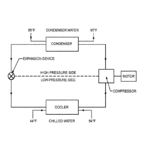
Basic System
An exemplary refrigeration cycle of a basic liquid chiller system is shown in
Figure 1. Chilled water enters the cooler at 54 F, for example, and leaves at
44 F.
Condenser water leaves a cooling tower at 85 F, enters the condenser, and
returns to
the cooling tower near 95 F. Condensers may also be cooled by air or
evaporation of
water. This system, with a single compressor and one refrigerant circuit with
a water-
cooled condenser, is used extensively to chill water for air conditioning
because it is
relatively simple and compact. The compressor can be a reciprocating, scroll,
screw,
or centrifugal compressor. The preferred systems of the present invention are
centrifugal liquid chiller systems.
Liquid chiller systems can also be used to fulfill heating requirement through
heat recovery. Heat recovery is the process of capturing the heat that is
normally
rejected from the chiller condenser and using it for space heating, domestic
water
heating, or another process requirement. For water-cooled chillers, it can be
accomplished either by operating at higher condensing temperatures and
recovering
heat from the water leaving the standard condenser, or by using a separate
condenser.
It can also be done by recovering heat from the refrigerant using a heat
exchanger,
preferably between the compressor and the condenser. Heat recovery in air-
cooled
chiller necessarily involves recovering heat from the refrigerant. The
preferred heat
recovery systems of the present invention are heat recovery centrifugal
chillers.
A centrifugal compressor uses rotating elements to accelerate the refrigerant
radially, and typically includes an impeller and diffuser housed in a casing.
Centrifugal compressors usually take fluid in at an impeller eye, or central
inlet of a
circulating impeller, and accelerate it radially outwardly. Some static
pressure rise
occurs in the impeller, but most of the pressure rise occurs in the diffuser
section of
the casing, where velocity is converted to static pressure. Each impeller-
diffuser set is
a stage of the compressor. Centrifugal compressors are built with from 1 to 12
or
more stages, depending on the final pressure desired and the volume of
refrigerant to
be handled. A compressor with more than one stage is called a multistage
compressor.
4
CA 02940623 2016-08-24
WO 2015/130589
PCT/US2015/017032
Centrifugal compressors may use lubricating oil or may be oil-free. An
example of oil-free compressors is those with magnetic bearings, where the
rotor shaft
is levitated between magnetic bearings and is preferably rotated using a
direct drive
motor, particularly a permanent magnet direct drive motor. Another example of
oil-
free compressors is those using hybrid bearing systems without oil, such as
those
using ceramic rolling elements.
The pressure ratio, or compression ratio, of a compressor is the ratio of
absolute discharge pressure to the absolute inlet pressure. Pressure delivered
by a
centrifugal compressor is practically constant over a relatively wide range of
capacities. Therefore, in order to maintain the centrifugal compressor
performance
while replacing the existing refrigerant, the pressure ratio when using the
new
refrigerant should be as close as possible to that when using the existing
refrigerant.
Unlike a positive displacement compressor, a centrifugal compressor depends
entirely on the centrifugal force of the high speed impeller to compress the
vapor
passing through the impeller. There is no positive displacement, but rather
what is
called dynamic-compression.
The pressure a centrifugal compressor can develop depends on the tip speed of
the impeller. Tip speed is the speed of the impeller measured at its tip and
is related to
the diameter of the impeller and its revolutions per minute. The capacity of
the
centrifugal compressor is determined by the size of the passages through the
impeller.
This makes the size of the compressor more dependent on the pressure required
than
the capacity.
In order to maintain the centrifugal compressor performance while replacing
the existing refrigerant, the predetermined impeller Mach number should be the
same
as that achieved by the existing refrigerant. Since impeller Mach number is
dependent
upon the acoustic velocity (speed of sound) of refrigerant, the performance of
a
compressor can more accurately be maintained by formulating a replacement
refrigerant which has the same acoustical velocity as the original
refrigerant, or which
has an acoustical velocity which theoretically will provide the same impeller
Mach
number as the existing refrigerant.
An important consideration for compressors, especially when replacing an
existing refrigerant with a new one, is the dimensionless specific speed, D.,
defined
here as:
5
CA 02940623 2016-08-24
WO 2015/130589
PCT/US2015/017032
0)VT7
(A03/4
where co is the angular velocity (rad/s), V is the volume flow rate (m3/s) and
Ah is the
ideal specific work (J/kg) per compressor stage, which can be approximated as:
Ah = 1/2 ¨ h, ¨(s2 s1) T2 ¨T
ln(T2/Ti )
where the subscripts 1 and 2 denotes the gas state at the compressor inlet and
outlet
respectively. H, s, and Tare respectively the specific enthalpy, specific
entropy, and
temperature. Compressors operate with the highest adiabatic efficiency, /7,
when the
S-2, has the optimum value for the design.
Because of its high speed operation, a centrifugal compressor is fundamentally
a high volume, low pressure machine. A centrifugal compressor works best with
a
low pressure refrigerant, such as trichlorofluoromethane (CFC-11). When part
of the
chiller, particularly the evaporator, is operated with at a pressure level
below ambient,
the chiller is referred to as a negative pressure system. One of the benefits
of a low
pressure or negative pressure system is low leak rates. Refrigerant leaks are
driven by
pressure differentials, so lower pressures will result in lower leak rates
than high
pressure systems. Also, leaks in the system operating at below ambient
pressure
result in air being sucked into the equipment rather than refrigerant leaking
out.
While such operation requires a purge device to remove any air and moisture,
monitoring the purge operation serves as a warning system for developing
leaks.
Summary of The Invention
In the present invention, it was discovered that chloro-trifluoropropenes are
particularly useful refrigerants for liquid chiller systems, particularly in
negative-
pressure chiller systems, such as for the replacement of R-11 and R-123. The
chloro-
trifluoropropenes of the present invention were discovered to provide
operating
conditions comparable to current chiller refrigerants and also to be
compatible with
current chiller lubricants. The chloro-trifluoropropenes of the present
invention are
preferrably 1-chloro-3,3,3-trifluoropropene and/or 2-chloro-3,3,3-
trifluoropropene,
and more preferrably trans-l-chloro-3,3,3-trifluoropropene.
6
CA 02940623 2016-08-24
WO 2015/130589
PCT/US2015/017032
Brief Description of the Drawings
Figure 1 is a schematic of a typical chiller system.
Figure 2 is a chart of COP for R-123, R-1233zd, and R-1234yf at an evaporator
temperature of -10 C.
Figure 3 is a chart of CAP for R-123, R-1233zd, and R-1234yf at an evaporator
temperature of -10 C.
Figure 4 is a chart of COP for R-123, R-1233zd, and R-1234y1 at an evaporator
temperature of 0 C.
Figure 5 is a chart of CAP for R-123, R-1233zd, and R-1234yf at an evaporator
temperature of 0 C
Figure 6 is a chart of COP for R-123, R-1233zd, and R-1234yf at an evaporator
temperature of 5 C.
Figure 7 is a chart of CAP for R-123, R-1233zd, and R-1234yf at an evaporator
temperature of 5 C.
Figure 8 is a chart of COP for R-123, R-1233zd, and R-1234yf at an evaporator
temperature of 10 C
Figure 9 is a chart of CAP for R-123, R-1233zd, and R-1234yf at an evaporator
temperature of 10 C
Detailed Description of The Invention
The chloro-trifluoropropene refrigerant composition of the present invention
can be added to a new chiller system or be employed in a method of topping-off
or
retrofitting an existing chiller system. The chloro-trifluoropropene
refrigerant
composition of the present invention is particularly useful in chillers,
preferably those
operated at negative pressure, using centrifugal compressors and flooded
evaporators.
The retrofit method, comprises the steps of removing the existing refrigerant
from the
chiller system while optionally retaining a substantial portion of the
lubricant in said
system; and introducing to said system a composition comprising a chloro-
trifluoropropene refrigerant of the present invention which is miscible with
the
lubricant present in the system without the need for addition surfactants
and/or
solubilizing agents. In topping-off an existing chiller system, the chloro-
trifluoropropene refrigerant of the present invention is added to top-off a
refrigerant
charge or as a partial replacement either to replace refrigerant lost or after
removing
part of the existing refrigerant and then adding the chloro-trifluoropropene
refrigerant
7
CA 02940623 2016-08-24
WO 2015/130589
PCT/US2015/017032
of the present invention. The preferred chloro-trifluoropropene refrigerant of
the
present invention is preferrably 1-chloro-3,3,3-trifluoropropene and/or 2-
chloro-3,3,3-
trifluoropropene, and more preferrably trans-l-chloro-33,3-trifluoropropene.
As used herein, the term "substantial portion" refers generally to a quantity
of
.. lubricant which is at least about 50% (all percentages herein are by weight
unless
indicated otherwise) of the quantity of lubricant contained in the
refrigeration system
prior to removal of the prior refrigerant. Preferably, the substantial portion
of
lubricant in the system according to the present invention is a quantity of at
least
about 60% of the lubricant contained originally in the refrigeration system,
and more
preferably a quantity of at least about 70%.
Any of a wide range of known methods can be used to remove prior
refrigerants from a chiller system while removing less than a major portion of
the
lubricant contained in the system. According to preferred embodiments, the
lubricant
is a hydrocarbon-based lubricant and the removal step results in at least
about 90%.
and even more preferably at least about 95%, of said lubricant remaining in
the
system. The removal step may readily be performed by pumping the original
refrigerants in the gaseous state out of a refrigeration system containing
liquid state
lubricants, because refrigerants are quite volatile relative to traditional
hydrocarbon-
based lubricants. The boiling point of refrigerants are generally under 30 C
whereas
the boiling point of mineral oils are generally over 200 C. Such removal can
be
achieved in any of a number of ways known in the art, including, the use of a
refrigerant recovery system. Alternatively, a cooled, evacuated refrigerant
container
can be attached to the low pressure side of a refrigeration system such that
the
gaseous prior refrigerant is drawn into the evacuated container and removed.
.. Moreover, a compressor may be attached to a refrigeration system to pump
the prior
refrigerant from the system to an evacuated container. In light of the above
disclosure,
those of ordinary skill in the art will be readily able to remove the prior
refrigerants
from chiller systems and to provide a refrigeration system comprising a
chamber
having therein a hydrocarbon-based lubricant and a chloro-trifluoropropene
refrigerant according to the present invention.
A method of the present invention comprises introducing to a chiller system, a
composition comprising at least one chloro-trifluoropropene refrigerant of the
present
invention miscible with the lubricant present in the system, if a lubricant is
used. The
8
CA 02940623 2016-08-24
WO 2015/130589
PCT/US2015/017032
lubricants in the chiller system can be hydrocarbon lubricating oils,
oxygenated
lubrication oils or mixtures thereof.
An embodiment of the present invention is a chiller system comprising (1) a
compressor, (2) at least one liquid cooler, (3) at least one condenser, and
(4) a chloro-
trifluoropropene refrigerant of the present invention. The compressor of said
chiller
system is preferably a centrifugal compressor. In an embodiment of the present
invention, the compressor in the chiller system has from 1 to 12 stages,
preferably 2
or 3 stages, even more preferably 2 stages. In an embodiment of the present
invention, the compressor in the chiller system uses a lubricating oil. In
another
embodiment of the present invention, the compressor is an oil-free compressor,
preferably an oil-free compressor using magnetic bearings or using hybrid
bearings.
In another embodiment of the present invention, the compressor in the chiller
system is an oil-free compressor where the chloro-trifluoropropene refrigerant
of the
present invention acts a lubricating agent. In an embodiment of the present
invention,
the liquid cooler in the chiller system is a flooded evaporator. In an
embodiment of
the present invention, the condenser in the chiller system is a water-cooled
condenser.
In another embodiment of the present invention, the condenser of the chiller
system is
an air-cooled condenser.
In another embodiment of the present invention, the chiller system is a heat
recovery chiller system comprising (1) a compressor, (2) at least one liquid
cooler, (3)
one or more condensers, and (4) a chloro-trifluoropropene refrigerant of the
present
invention. In another embodiment of the present invention, the liquid cooler
of the
chiller system is preferably a flooded evaporator, with one portion operated
at a
pressure below atmospheric pressure. In another embodiment of the present
invention, the chiller system is a heat recovery chiller system containing one
or
multiple water-cooled condensers, and heat is recovered from the water leaving
one of
the condensers. In another embodiment of the present invention, the chiller
system is
a heat recovery chiller system and the condenser of the heat recovery chiller
system is
a water-cooled condenser or air-cooled condenser and heat is recovered from
the
refrigerant. In another embodiment, the chiller system is a heat recovery
chiller
system where the compressor is a centrifugal compressor.
Another embodiment of the present invention is a process for producing
heating in a heat recovery chiller system or heat-pump chiller. In an
embodiment of
the present invention, the liquid cooler of the chiller system in the method
is
9
CA 02940623 2016-08-24
WO 2015/130589
PCT/US2015/017032
preferably a flooded evaporator with one portion operated at a pressure below
atmospheric pressure. In an embodiment of the present invention, at least one
of the
condensers of the chiller system in the method is preferably operated at
temperatures
ranging from about 26.7 C (80 F) to 60 C (140 F), preferably from about 29.4 C
(85 F) to 55 C (131 F).
Another embodiment of the present invention is a method of producing
cooling using the chiller system of the present invention. In an embodiment of
the
present invention, the method of producing cooling uses a liquid cooler of the
chiller
system which is preferably a flooded evaporator with one portion operated at a
pressure below atmospheric pressure. In an embodiment of the present
invention, the
method of producing cooling uses a condenser of the chiller system that is
preferably
operated at temperatures ranging from about 26.7 C (80 F) to 60 C (140 F),
preferably from about 29.4 C (85 F) to 55 C (131 F).
In an embodiment of the present invention, the chloro-trifluoropropene
refrigerant is 1-chloro-3,3,3-fluoropropene, which may comprise a mixture of
the
trans- and cis-isomers of 1-chloro-3,3,3-fluoropropene, preferably
predominantly the
trans-isomer, more preferably greater than 70wt% of the trans-isomer, more
preferably greater than 90wt% of the trans-isomer, more preferably greater
than
97wt% of the trans-isomer, and even more preferably greater than 99wt% of the
trans-
isomer. In another embodiment of the present invention, the chloro-
trifluoropropene
refrigerant is essentially trans-l-chloro-3,3,3-trifluoropropene.
Another embodiment of the present invention is a process for producing
cooling in a chiller system comprising compressing a refrigerant in a
compressor, and
evaporating the refrigerant in the vicinity of a body to be cooled, wherein
said
refrigerant comprises chloro-trifluoropropene.
In an embodiment of the present invention, the refrigerant of the present
invention has an acoustic velocity close to that of R-123 or R-11, preferably
where the
acoustic velocity of the refrigerant of the present invention is within 10% of
the
acoustic velocity of R-123 or R-11 at conditions at the inlet of the
compressor of the
chiller system. In another embodiment of the present invention, the acoustic
velocity
of the refrigerant of the present invention is less than about 150 m/s at 40 C
and 1 bar,
preferably less than about 145 m/s at 40 C and 1 bar. In another embodiment of
the
present invention, the acoustic velocity of the refrigerant of the present
invention is
from about 130 to about 150 m/s at conditions of the compressor of the chiller
system.
In addition to the chloro-trifluoropropene refrigerant of the present
invention,
the composition introduced into the system can include an additional
refrigerant
selected from hydrofluoroolefins, hydrofluorcarbons, hydrochlorofluorocarbons,
chlorofluorocarbons,
hydrochloroolefins, hydrofluoroethers, fluoroketones, hydrocarbons, ammonia,
or
mixtures thereof, preferably where the additional refrigerant is non-flammable
and/or
the resulting refrigerant composition is non-flammable.
The hydrofluorocarbon can be selected from difluromethane (HFC-32), 1-
fluoroethane (HFC-161), 1,1-difluoroethane (HFC-152a), 1,2-difluoroethane (HFC-
152), 1,1,1-trifluoroethane (HFC-143a), 1,1,2-trifluoroethane (HFC-143),
1,1,1,2-
tetrafluoroethane (HFC-134a), 1,1,2,2-tetrafluoroethane (HFC-134),
pentafluoroethane (HFC-125), 1,1,1,2,3-pentafluoropropane (HFC-245eb),
1,1,1,3,3-
pentafluoropropane (HFC-245fa), 1,1,2,2,3-pentafluoropropane (HFC-245ca),
1,1,1,3,3,3-hexafluoropropane (HFC-236fa), 1,1,1,2,3,3,3-heptafluoropropane
(HFC-
227ea), 1,1,1,3,3-pentafluorbutane (HFC-365mfc), 1.1,1,2,3,4.4,5,5,5-
decafluoropropane (HFC-4310) and mixtures thereof.
The hydrochlorofluorocarbon can be selected from 1,1-dichloro-2,2,2-
trifluoroethane (R-123), 1-chloro-1,2,2,2-tetrafluoroethane (R-124), 1,1 -
dichloro-l-
fluoroethane (R-141b). 1-chloro-1,1-difluoroethane (R-142b) and mixtures
thereof,
preferably R-123.
The chlorofluorcarbons can be trichlorofluoromethane (R-11),
dichlorodifluoromethane (R-12), 1,1,2-trichloro-1.2.2-trifluoroethane (R-113),
1,2-
dichloro-1,1,2,2-tetrafluoroethane (R-114). chloropentafluoroethane (R-115),
or
mixtures thereof, preferably R-11.
Exemplary hydrofluoroethers include 1,1,1,2,2,3,3-heptafluoro-3-methoxy-
propane, 1,1,1,2,2,3,3,4.4-nonafluoro-4-methoxy-butane, or mixtures thereof.
An
exemplary fluoroketone is 1,1,1,2,2.4,5,5,5-nonafluoro-4(trifluoromethyl)-3-
pentanone.
The hydrofluoroolefins can be a C3 to C5 hydrofluoroolefin containing at least
one fluorine atom, at least one hydrogen atom and at least one alkene linkage.
Exemplary hydrofluoroolefins include 3,3,3-trifluoropropene (HF0-1234z1), E-
1,3,3,3-tetrafluoropropene, (E-HF0-1234ze), Z-1,3,3,3-tetrafluoropropene (Z-
HFO-
1234ze), 2,3,3,3-tetrafluoropropene (HF0-1234yf), E-1,2,3,3,-
pentafluoropropene (E-
11
Date Recue/Date Received 2021-08-20
CA 02940623 2016-08-24
WO 2015/130589
PCT/US2015/017032
HF0-1255ye). Z-1,2,3,3,3-pentafluoropropene (Z-HF0-125ye), E-1,1,1,3,3,3-
hexafluorobut-2-ene (E-HF0-1336mzz), Z-1,1,1,3,3,3-hexafluorobut-2-ene (Z-HFO-
1336mzz), 1,1,1,4,4,5,5,5-octafluoropent-2-ene (HF0-1438mzz) or mixtures
thereof.
An exemplary hydrochloroolefin is trans-1,2-dichloroethylene.
The hydrocarbons can C3 to C7 alkanes, preferably butanes, pentanes, or
mixtures thereof, more preferably n-pentane, isopentane, cyclopentane, or
mixtures
thereof.
Current chiller lubricants include, but are not limted to, mineral oils,
polyol
ester oils, polyalklylene glycol oils, polyvinyl ether oils, poly(alphaolefin)
oils, alkyl
benzene oils and mixtures thereof. Preferred chiller lubricants are mineral
oils, polyol
ester oils, and polyvinyl ether oils. The chloro-trifluopropenes of the
present
invention were found to be miscible with mineral oils as well as other chiller
lubricants.
In addition to the chloro-trifluoropropene refrigerant miscible with the
lubricant of the present invention, the composition introduced into the system
can
include other additives or materials of the type used in refrigerant
compositions to
enhance their performance in refrigeration systems. For example, the
composition can
include extreme pressure and antiwear additives, oxidation stability
improvers,
corrosion inhibitors, viscosity index improvers, pour and floc point
depressants,
antifoaming agents, viscosity adjusters, UV dyes, tracers, and the like.
The following non-limiting examples are hereby provided as reference:
Examples
Liquid Chiller Performance Data
The performance of the refrigerants R-123 (1,1-dichloro-2,2,2-
trifluoroethane), R-1233zd (1-chloro-3,3,3-trifluoropropene, predominantly
trans-
isomer), and R-1234yf (2,3,3,3-tetrafluoropropene) in a liquid chiller
application were
evaluated in the following examples. In each example, data is provided at a
given
evaporator temperature and at multiple condenser temperatures, ranging from 30
C to
55 C. The isentropic efficiency in each case was 0.7. Data for R-123 and R-
1234yf
are provided as comparative examples.
In the following examples, the following nomenclature is used:
12
GA 02940623 2016-08-24
WO 2015/130589
PCT/US2015/017032
Condenser discharge temperature: T cond
Condenser pressure: P cond
Evaporator pressure: P evap
Pressure difference between condenser and evaporator: P diff
Pressure ratio of the condenser to the evaporator: P ratio
Coefficient of Performance (energy efficiency): COP
Capacity: CAP
EXAMPLE 1
In this example, the following conditions were used:
Evaporator temperature = -10 C. Compressor inlet temperature = -5 C.
Isentropic
efficiency = 0.7. The results are tabulated in Table 1.
Figures 2 and 3 show the COP and CAP of R-1233zd and R-1234yf relative to R-
123.
Table 1:
T evap -10 C
Internal heat exchanger
inlet compressor -5 C
isentropic efficiency 0,7
Tcond evap P cond P P diff P ratio CAP
COP
( C) (kPa) (kPa) (kPa) (P/P) (KJ/d)
R-1234yf 30.0 219 772 554 3.53 1456 3.6
35.0 219 882 663 4.03 1372 3.1
40.0 219 1003 785 4.58 1287 2.7
45.0 219 1137 918 5.19 1200 2.3
50.0 219 1283 1064 5.86 1111 2.0
55.0 219 1443 1224 6.59 1019 1.7
R-1233zd 30.0 28 155 127 5.51 280 3.9
35.0 28 184 156 6.54 269 3.4
40.0 28 217 189 7.71 257 2.9
45.0 28 254 226 9.04 245 2.6
50.0 28 296 268 10.52 233 2.3
55.0 28 343 314 12.18 222 2.1
R-123 30.0 20 110 90 5.44 206 4.0
35.0 20 131 111 6.47 199 3.5
40.0 20 155 135 7.66 192 3.1
45.0 20 182 162 9.00 184 2.7
50.0 20 213 192 10.52 177 2.4
55.0 20 247 227 12.23 169 2.2
13
GA 02940623 2016-08-24
WO 2015/130589
PCT/US2015/017032
EXAMPLE 2
In this example, the following conditions were used:
Evaporator temperature = 0 C. Compressor inlet temperature = 5 C. Isentropic
efficiency = 0.7. The results are tabulated in Table 2.
Figures 4 and 5 show the COP and CAP of R-1233zd and R-1234yf relative to R-
123.
Table 2:
T evap 0 C
Internal heat exchanger
inlet compressor 5 C
isentropic efficiency 0,7
Tcond evap P cond P P diff P ratio CAP
COP
( C) (kPa) (kPa) (kPa) (P/P) (KJ/m3)
R-1234yf 30.0 312 772 461 2.48 2152 5.3
35.0 312 882 570 2.83 2035 4.4
40.0 312 1003 691 3.22 1915 3.7
45.0 312 1137 825 3.64 1793 3.1
50.0 312 1283 971 4.11 1668 2.7
55.0 312 1443 1131 4.62 1540 2.3
R-1233zd 30.0 46 155 109 3.37 463 5.6
35.0 46 184 138 4.00 444 4.7
40.0 46 217 171 4.72 426 4.0
45.0 46 254 208 5.53 407 3.5
50.0 46 296 250 6.43 389 3.0
55.0 46 343 297 7.45 370 2.7
R-123 30.0 33 110 77 3.36 337 5.7
35.0 33 131 98 4.00 325 4.8
40.0 33 155 122 4.74 314 4.1
45.0 33 182 149 5.57 302 3.6
50.0 33 213 180 6.51 290 3.1
55.0 33 247 215 7.56 279 2.8
EXAMPLE 3
In this example, the following conditions were used:
Evaporator temperature = 5 C. Compressor inlet temperature = 10 C. Isentropic
efficiency = 0.7. The results are tabulated in Table 3.
Figures 6 and 7 show the COP and CAP of R-1233zd and R-1234yf relative to R-
123.
14
CA 02940623 2016-08-24
WO 2015/130589 PCT/US2015/017032
Table 3:
T evap 5 C
Internal heat exchanger
inlet compressor 10 C
isentropic efficiency 0,7
Tcond evap P cond P P diff T-out comp CAP COP
( C) (kPa) (kPa) (kPa) (KJ/M3)
R-1234yf 30.0 368 772 404 39 2610 6.7
35.0 368 882 514 45 2472 5.4
40.0 368 1003 635 51 2332 4.4
45.0 368 1136 768 56 2188 3.7
R-1233zd 30.0 58 154 96 44 585 7.0
35.0 58 183 125 50 562 5.7
40.0 58 216 158 55 539 4.8
45.0 58 254 196 61 516 4.1
R-123 30.0 41 110 69 44 423 7.2
35.0 41 131 90 50 409 5.8
40.0 41 155 114 56 395 4.9
45.0 41 182 141 61 381 4.2
EXAMPLE 4
In this example, the following conditions were used:
Evaporator temperature = 10 C. Compressor inlet temperature = 15 C. Isentropic
efficiency = 0.7. The results are tabulated in Table 4.
Figures 8 and 9 show the COP and CAP of R-1233zd and R-1234yf relative to R-
123.
GA 02940623 2016-08-24
WO 2015/130589
PCT/US2015/017032
Table 4:
T evap 10 C
Internal heat exchanger
inlet compressor 15 C
isentropic efficiency 0,7
Tcond evap P cond P P diff P ratio CAP COP
( C) (kPa) (kPa) (kPa) (P/P) (KJ/m3)
R-1234yf 30.0 432 772 340 1.79 3097 8.7
35.0 432 882 450 2.04 2936 6.7
40.0 432 1003 571 2.32 2773 5.4
45.0 432 1137 705 2.63 2606 4.4
50.0 432 1283 851 2.97 2435 3.7
55.0 432 1443 1011 3.34 2258 3.1
R-1233zd 30.0 72 155 83 2.16 731 9.1
35.0 72 184 112 2.57 703 7.1
40.0 72 217 145 3.03 674 5.8
45.0 72 254 182 3.55 646 4.8
50.0 72 296 224 4.13 618 4.1
55.0 72 343 271 4.78 591 3.6
R-123 30.0 51 110 59 2.17 528 9.3
35.0 51 131 80 2.58 510 7.3
40.0 51 155 104 3.05 493 5.9
45.0 51 182 131 3.59 475 5.0
50.0 51 213 162 4.19 458 4.3
55.0 51 247 196 4.88 440 3.7
Representative data from Tables 1 through 4 is charted in Figures 2 through 9.
In all of these examples, the efficiency of R-1233zd was very close to that of
R-123, being within a few percent of the efficiency of R-123. In contrast, the
efficiency of R-1234yf was significantly lower than that of R-1233zd and R-
123,
being from 6.4% lower to over 20% lower than that of R-123. It was also
unexpectedly discovered that the capacity of R-1233zd was from 30% to 40%
greater
than that of R-123.
It is also shown that for R-1233zd and for R-123 the system is operated as a
negative-pressure system, where the pressure in the evaporator is below
ambient. For
R-1234yf the entire system is operated at positive-pressure.
R-1233zd was found to provide a close match to operating pressures, pressure
ratio, and pressure difference of R-123 and can be used as a more
environmentally
acceptable replacement.
16
CA 02940623 2016-08-24
WO 2015/130589
PCT/US2015/017032
EXAMPLE 5
Liquid Chiller Performance Data for Trans-1233zd and Cis-1233zd
The performance of cis and trans 1233zd in a single-stage liquid chiller was
evaluated in the following examples. In each example, data is provided at a
given
evaporator temperature and at multiple condenser discharge temperatures,
ranging
from 30 C to 45 C. In each case, there is 5 C of evaporator superheat and 5 C
of
condenser subcooling. The isentropic compressor efficiency in each case was
0.7.
In the following examples, the following nomenclature is used:
Evaporator temperature: Tevap
Condenser discharge temperature: Tcond
Condenser pressure: cond P
Evaporator pressure: evap P
Coefficient of Performance (energy efficiency): COP
Capacity: CAP
The trans-1233zd (1-chloro-3,3,3-trifluoropropene, >99% trans-isomer) and cis-
1233zd (cis-l-chloro-3,3,3-trifluoropropene, >99% cis-isomer) are evaluated
for use
in a single-stage chiller as explained above. The results are shown in Tables
5 to 8.
Table 5: Evaporator Temperature = -10 C
Tcond evap P cond P CAP COP
( C) (k Pa) (k Pa) (KJ/nI3)
30.0 31 154 308 4.12
35.0 31 182 297 3.58
trans-1233zd
40.0 31 214 286 3.14
45.0 31 250 274 2.78
30.0 12 75 134 4.08
35.0 12 91 128 3.53
cis-1233zd
40.0 12 109 123 3.09
45.0 12 130 117 2.73
17
CA 02940623 2016-08-24
WO 2015/130589
PCT/US2015/017032
Table 6: Evaporator Temperature -= 0 C
Tcond evap P cond P CAP COP
( C) (kPa) (kPa) ( KJ/m3)
30.0 49 154 492 5.92
35.0 49 182 475 4.97
trans-1233zd
40.0 49 214 457 4.25
45.0 49 250 440 3.69
30.0 20 75 230 5.90
35.0 20 91 221 4.94
cis-1233zd
40.0 20 109 212 4.21
45.0 20 130 203 3.64
Table 7: Evaporator Temperature = 5 C
Tcond evap P cond P CAP COP
( C) (kPa) (kPa) ( KJ/m3)
30.0 60 154 613 7.37
35.0 60 182 592 6.02
trans-1233zd
40.0 60 214 571 5.05
45.0 60 250 549 4.32
30.0 26 75 296 7.36
35.0 26 91 285 6.00
cis-1233zd
40.0 26 109 274 5.02
45.0 26 130 262 4.28
Table 8: Evaporator Temperature = 10 C
Tcond evap P cond P CAP COP
( C) (kPa) (kPa) (KJ/m3)
30.0 74 154 757 9.54
35.0 74 182 732 7.49
trans-1233zd
40.0 74 214 706 6.11
45.0 74 250 680 5.12
30.0 32 75 378 9.55
35.0 32 91 364 7.48
cis-1233zd
40.0 32 109 350 6.09
45.0 32 130 336 5.09
The COP of trans-1233zd is about the same or greater than cis-1233zd while the
capacity of trans-1233zd is about twice that or more than cis-1233zd.
18
CA 02940623 2016-08-24
WO 2015/130589
PCT/US2015/017032
EXAMPLE 6
Mixtures of trans-1233zd and cis-1233zd:
To examine the potential effect of a mixture of both trans- and cis-isomers on
the
performance or operation of a centrifugal chiller, a vapor-liquid equilibrium
test on a
mixture of trans-1233zd and cis-1233zd was conducted to evaluate the potential
for
fractionation.
To a clean, glass 35mL sampling vial was added 4.0 gram of cis-1233zd and 16.1
gram of trans-1233zd, providing an overall ratio of cis-1233zd-to-trans-1233zd
of
19.9 / 80.1 wt/wt. The mixture was left to equilibrate to room temperature.
The
vapor portion and the liquid portion were analyzed by Gas Chromatography (GC).
The ratio of cis-to-trans isomers in the vapor portion was found to be
12.2/87.8 wt/wt;
the ratio of cis-1233zd-to-trans-1233zd in the liquid portion was
significantly
different, and found to be 21.3/78.6 wt/wt. This exemplifies that mixtures of
trans-
1233zd and cis-1233zd may fractionate as is a zeotropic mixture.
EXAMPLE 7
Acoustic Velocity:
The acoustic velocity for R-11, R-123, R-134a, R-1233zd and R-1234yf were
determined at 40 C and 1 bar. The acoustic velocity of R-1233zd is close to
that of
R-11 and closer to that of R-123 than either R-134a or R-1234y1.
Table 9: Acoustic Velocity of Refrigerants
Conditions: 40 C and 1 bar.
Refrigerant Acoustic Velocity
(m/s)
R123 131.9
R-11 142.0
R-1233zd 143.7
R-1234yf 155.6
R-134a 165.7
19
CA 02940623 2016-08-24
WO 2015/130589
PCT/US2015/017032
EXAMPLE 8
Dimensionless Specific Speed:
The performance of R-123, R-1233zd. and R-1234yf in a liquid chiller was
determined as in example 2, with a compressor inlet temperature at 5 C and a
.. condenser temperature at 40 C. The results are shown in Table 10, which
also gives
the ratio of the dimensionless specific speed, S/, of the refrigerant to that
of R-123
(n123), assuming the chillers are operated to deliver the same capacity of
cooling. R-
1233zd was found to be a good replacement for R-123 as compared to R-1234yf.
.. Table 10: Dimensionless Specific Speed of Refrigerants at Equivalent
Cooling
Capacity
Evaporator Temp: 5 C. Condenser Temp: 40 C
Refrigerant Compressor P Temp nal, 23
(bar) ( C)
R123 inlet 0.33 5 1
outlet 1.55 58
R-1233zd inlet 0.46 5 0.76
outlet 2.17 58
R-1234yf inlet 3.12 5 0.44
outlet 10.03 52
These results show that R-1233, particularly R-1233zd is useful as a
.. refrigerant for liquid chillers, particularly negative-pressure chillers,
and especially in
large systems due to the efficiency benefits of R-1233zd over R-1234yf or
similar
refrigerants.