Note: Descriptions are shown in the official language in which they were submitted.
CA 02941056 2016-09-06
HIGHLY FORMABLE SMART SUSCEPTOR BLANKETS
Field of the Disclosure
The present disclosure relates generally to heating blankets and, more
particularly, to
a heating blanket and method for heating a structure to a substantially
uniform temperature
across the structure.
Background of the Disclosure
Heating blankets can be used for many different purposes. In industrial
applications,
for example, heating blankets may be used in manufacturing and repair of
composite
structures by providing a localized application of heat. However, conventional
heating
blankets do not provide uniform temperatures across an area that is being
heated, especially if
that area has contoured surfaces. As a result, differential heating across the
area causes
certain spots to be over-heated while other spots are under-heated.
Summary of the Disclosure
In accordance with one embodiment, a method for heating a contoured surface is
disclosed. The method may include placing on the contoured surface a heating
blanket
including a conductor configured to generate a magnetic field in response to
an electrical
current, a plurality of susceptors configured to generate heat in response to
the magnetic field
and composed of a magnetic material having a Curie point, and a matrix
surrounding the
conductor and the plurality of susceptors and composed of a material that
becomes
conformable at a first predetermined temperature. The method may also include
providing
electrical current to the heating blanket to increase a temperature of the
matrix to at least the
.. first predetermined temperature, and allowing the heating blanket to
conform to the
contoured surface.
In a refinement, the method may further include increasing the electrical
current to the
heating blanket to increase the temperature of the matrix to a second
predetermined
temperature.
In another refinement, the method may further include providing an uncured
composite patch on the contoured surface before placing the heating blanket on
the contoured
surface.
CA 02941056 2016-09-06
In another refinement, the method may further include providing a vacuum bag
assembly over the uncured composite patch and the heating blanket, and
applying a vacuum
to the vacuum bag assembly before providing electrical current to the heating
blanket.
In another refinement, the method may further include supplying electrical
current to
the heating blanket to maintain the second predetermined temperature for a
predetermined
time period until the uncured composite patch is cured.
In accordance with another embodiment, a method for repairing a contoured
surface
of a structure is disclosed. The method may include inserting an uncured
composite patch on
the contoured surface of the structure, and placing on the uncured composite
patch a heating
blanket including a thermoplastic matrix, a conductor embedded in the
thermoplastic matrix
and configured to generate a magnetic field in response to an electrical
current, and a
plurality of susceptors embedded in the thermoplastic matrix, configured to
generate heat in
response to the magnetic field, and composed of a magnetic material having a
Curie point.
The method may also include installing a vacuum bag assembly over the uncured
composite patch and the heating blanket, and applying a vacuum to the vacuum
bag
assembly. The method may also include providing electrical current to the
conductor to
increase a temperature of the heating blanket to a first predetermined
temperature, and
continuing supply of electrical current to the conductor to maintain the first
predetermined
temperature such that the thermoplastic matrix becomes conformable and
conforms to the
contoured surface of the structure.
In a refinement, the method may further include increasing the electrical
current to the
conductor to increase the temperature of the heating blanket to a second
predetermined
temperature, and continuing supply of the increased electrical current to the
conductor to
maintain the second predetermined temperature for a predetermined time period
to complete
curing of the uncured composite patch.
In another refinement, the method may further include ceasing supply of
electrical
current to the conductor, allowing the temperature of the heating blanket to
reach a room
temperature, removing the vacuum bag assembly, and removing the heating
blanket from the
contoured surface of the structure.
In accordance with another embodiment, a heating blanket is disclosed. The
heating
blanket may include a thermoplastic matrix configured to become conformable at
a
predetermined temperature, a conductor embedded in the thermoplastic matrix
and
configured to receive electrical current and generate a magnetic field in
response to the
2
electrical current, and a plurality of susceptors embedded in the
thermoplastic matrix and
composed of a magnetic material.having a Curie point.
In a refinement, the thermoplastic matrix may be prefoinied to a shape of a
contoured
composite structure.
In another refinement, the Curie point of the plurality of susceptors may be
greater
than the predetermined temperature of the thermoplastic matrix.
In another refinement, the thermoplastic matrix may be composed of
polyethylene.
In another refinement, the plurality of susceptors may comprise at least a
first alloy
susceptor wire having a first Curie point and a second alloy susceptor wire
having a second
Curie point different than the first Curie point.
In another refinement, the heating blanket may further comprise reinforcing
fibers
configured to reduce deformation of the conductor in the thermoplastic matrix.
In another refinement, the reinforcing fibers may surround the conductor and
the
=
plurality of susceptors.
In another refinement, the conductor may comprise a plurality of Litz wires
arranged
in parallel, and the heating blanket may further include a plurality of
threads tying the
plurality of Litz wires together.
In another refinement, the conductor may comprise a plurality of Litz wires
arranged
in a knitted configuration.
In another refinement, the conductor may comprise a plurality of Litz wires
arranged
in a sine wave configuration.
In another refinement, the thermoplastic matrix may include: a first
thermoplastic
material embedding the conductor and the plurality of susceptors therein, and
a second
thermoplastic material surrounding the first thermoplastic material, the
second thermoplastic
material having a minimum viscosity temperature that is lower than a minimum
viscosity
temperature of the first thermoplastic material.
In another refinement, the heating blanket may be preformed to a shape of a
contoured composite structure.
3
CA 2941056 2019-12-11
In accordance with yet another embodiment, a method for heating a contoured
surface
is provided. The method comprises: placing on the contoured surface a heating
blanket
including a conductor configured to generate a magnetic field in response to
an electrical
current, a plurality of susceptors configured to generate heat in response to
the magnetic field
and composed of a magnetic material having a Curie point, a matrix surrounding
the
conductor and the plurality of susceptors and composed of a material that
becomes
conformable at a first predetermined temperature, and reinforcing fibers
embedded in the
matrix and configured to reduce deformation of the conductor in the matrix;
providing
electrical current to the heating blanket to increase a temperature of the
matrix to at least the
first predetermined temperature; and allowing the heating blanket to conform
to the
contoured surface.
In accordance with yet another embodiment, a method for repairing a contoured
surface of a structure is provided.' The method comprises: inserting an
uncured composite
patch on the contoured surface of the structure; placing on the uncured
composite patch a
heating blanket including a thermoplastic matrix, a conductor embedded in the
thermoplastic
matrix and configured to generate a magnetic field in response to an
electrical current,
reinforcing fibers embedded in the thermoplastic matrix and configured to
reduce
deformation of the conductor in the thermoplastic matrix, and a plurality of
susceptors
embedded in the thermoplastic matrix, configured to generate heat in response
to the
magnetic field, and composed of a magnetic material having a Curie point;
installing a
vacuum bag assembly over the uncured composite patch and the heating blanket;
applying a
vacuum to the vacuum bag assembly; providing the electrical current to the
conductor to
increase a temperature of the heating blanket to a first predetermined
temperature; and
continuing supply of the electrical current to the conductor to maintain the
first
predetermined temperature such that the thermoplastic matrix becomes
conformable and
conforms to the contoured surface of the structure.
In accordance with yet another embodiment, a heating blanket is provided. The
heating blanket comprises: a thermoplastic matrix configured to become
conformable at a
predetermined temperature; a conductor embedded in the thermoplastic matrix
and
configured to receive electrical current and generate a magnetic field in
response to the
electrical current; reinforcing fibers embedded in the thermoplastic matrix
and configured to
reduce deformation of the conductor in the thermoplastic matrix; and a
plurality of susceptors
embedded in the thermoplastic matrix and composed of a magnetic material
having a Curie
point.
3a
CA 2941056 2019-12-11
In accordance with yet another embodiment, a heating blanket is provided. The
heating blanket comprises: a thermoplastic matrix configured to stretch and
become
conformable to a contoured surface at a predetermined temperature, and to,
solidify upon
cooling; a conductor embedded in the thermoplastic matrix and configured to
receive
electrical current and generate a magnetic field in response to the electrical
current; and a
plurality of susceptors embedded in the thermoplastic matrix and composed of a
magnetic
material having a Curie point, wherein the Curie point of the plurality of
susceptors is greater
than the predetermined temperature of the thermoplastic matrix.
In accordance with yet another embodiment, a method for heating a contoured
surface
is provided. The method comprises: placing on the contoured surface a heating
blanket
including a conductor configured to generate a magnetic field in response to
an electrical
current, a plurality of susceptors configured to generate heat in response to
the magnetic field
and composed of a magnetic material having a Curie point, and a thermoplastic
matrix
surrounding the conductor and the plurality of susceptors and composed of a
material that
becomes conformable at a first predetermined temperature, wherein the Curie
point of the
plurality of susceptors is greater than the first predetermined temperature;
providing electrical
current to the heating blanket to increase a temperature of the thermoplastic
matrix to at least
the first predetermined temperature; and allowing the heating blanket to
stretch and conform
to the contoured surface.
In accordance with yet another embodiment, a heating blanket is provided. The
heating blanket comprises: a thermoplastic matrix configured to become
conformable by
changing from a solid state to a pliable state when heated above a first
predetermined
temperature; a conductor wire embedded in the thermoplastic matrix and
configured to
receive electrical current and generate a magnetic field in response to the
electrical current;
and a susceptor wire embedded in the thermoplastic matrix and composed of a
magnetic
material having a Curie point, wherein the Curie point of the magnetic
material is equal to or
greater than the first predetermined temperature.
3b
CA 2941056 2019-12-11
In accordance with yet another embodiment, a heating blanket is provided. The
heating blanket comprises: a thermoplastic matrix configured to become
conformable by
changing from a solid state to a pliable state when heated above a
predetermined temperature;
a conductor wire having a plurality of Litz wires arranged in a sine wave
configuration, the
conductor wire configured to receive electrical current and generate a
magnetic field in
response to the electrical current; and a susceptor wire composed of a
magnetic material
having a Curie point, wherein the susceptor wire is wrapped around the
conductor wire in a
spiral configuration, the conductor wire and the susceptor wire are embedded
in the
thermoplastic matrix, and the Curie point of the magnetic material is equal-to
or greater than
the predetermined temperature.
These and other aspects and features will become more readily apparent upon
reading
the following detailed description when taken in conjunction with the
accompanying
drawings. In addition, although various features are disclosed in relation to
specific
exemplary embodiments, it is understood that the various features may be
combined with
each other, or used alone, with any of the various exemplary embodiments
without departing
from the scope of the disclosure.
=
=
3c
=
CA 2941056 2019-12-11
CA 02941056 2016-09-06
Brief Description of the Drawings
FIG. 1 is a perspective cutaway view of a heating blanket, in accordance with
one
embodiment of the present disclosure;
FIG. 2 is a perspective cutaway view of a heating blanket, in accordance with
another
embodiment;
FIG. 3 is a schematic view of the heating blanket in FIG. 1 with a housing and
a
matrix removed;
FIG. 4 is a side view of a conductor and susceptor arrangement that may be
used in a
heating blanket, in accordance with another embodiment;
FIG. 5 is a cross-sectional view of a heating blanket, in accordance with
another
embodiment;
FIG. 6 is a cross-sectional view of a heating blanket with reinforcing fibers,
in
accordance with another embodiment;
FIG. 7 is a schematic view of a plurality of Litz wires tied together by
threads in a
heating blanket, in accordance with another embodiment;
FIG. 8 is a schematic view of a plurality of Litz wires in a knitted
configuration, in
accordance with another embodiment;
FIG. 9 is a schematic view of a plurality of Litz wires in a sine wave
configuration, in
accordance with another embodiment;
FIG. 10 is a cross-sectional view of a heating blanket with various
thermoplastic
layers, in accordance with another embodiment;
FIG. 11 is side view of a heating blanket applied to a rework area of a
composite
structure, in accordance with another embodiment;
FIG. 12 is a cross-sectional view of the heating blanket applied to the rework
area of
the composite structure in FIG. 11;
FIG. 13 is a cross-sectional view of a vacuum bag assembly installed over the
heating
blanket and rework area of the composite structure in FIG. 12;
FIG. 14 is a cross-sectional view of the heating blanket conformed to a
contoured
surface of the composite structure in FIG. 12;
FIG. 15 is a side view of a preformed heating blanket, in accordance with
another
embodiment;
4
CA 02941056 2016-09-06
FIGS. 16 and 17 are a flowchart illustrating a process for heating a contoured
surface
of a structure, such as for repairing the contoured surface, in accordance
with another
embodiment;
FIG. 18 is a flow diagram of aircraft production and service methodology; and
FIG. 19 is a block diagram of an aircraft.
While the present disclosure is susceptible to various modifications and
alternative
constructions, certain illustrative embodiments thereof will be shown and
described below in
detail. The disclosure is not limited to the specific embodiments disclosed,
but instead
includes all modifications, alternative constructions, and equivalents
thereof.
Detailed Description
Reference will now be made in detail to specific embodiments or features,
examples
of which are illustrated in the accompanying drawings. Generally,
corresponding reference
numbers will be used throughout the drawings to refer to the same or
corresponding parts.
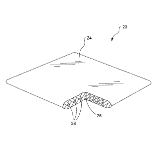
FIG. 1 illustrates a perspective cutaway view of a heating blanket 20, in
accordance
with an embodiment of the present disclosure. The heating blanket 20 may
comprise a matrix
24 with a conductor 26 and a plurality of susceptors 28 embedded therein.
Although not
required, the heating blanket 20 may also include a housing 22, as shown in
FIG. 2, that
contains the matrix 24. The housing 22 may be made of a same material as the
matrix 24.
Referring back to FIG. 1, the matrix 24 is composed of a thermoplastic
material or
other suitable material that becomes conformable, pliable, or moldable above a
minimum
viscosity temperature and solidifies upon cooling. In addition, the
thermoplastic material of
the matrix 24 is thermally conductive. For example, the thermoplastic material
may be
polyethylene. Polyethylene has a minimum viscosity temperature between an
approximate
range of 210 F to 240 F. However, other thermoplastic materials may be used.
By using
thermoplastic material for the matrix 24, the heating blanket 20 can stretch
and conform to
contoured surfaces once the minimum viscosity temperature is achieved. In so
doing, the
heating blanket 20 can provide uniform heat to an area to which the heating
blanket 20 is
applied.
Embedded within the matrix 24, the conductor 26 may be configured to receive
an
electrical current and generate a magnetic field in response to the electrical
current. In one
example, the conductor 26 may comprise a Litz wire, although other suitable
types of
conductors can be used as well. Referring now to FIG. 3, with continued
reference to FIG. 1
and FIG. 2, the conductor 26 is operatively connected to a portable or fixed
power supply 36,
5
CA 02941056 2016-09-06
such as via wiring 38. The power supply 36 may provide alternating current
electrical power
to the conductor 26 and may be connected to a conventional outlet.
In addition, the power supply 36 may operate at higher frequencies. For
example, the
minimum practical frequency may be approximately ten kilohertz, and the
maximum practical
frequency may be approximately four hundred kilohertz. However, other
frequencies may be
used. Furthermore, the power supply 36 may be connected to a controller 40 and
a voltage
sensor 42 or other sensing device configured to indicate a voltage level
provided by the power
supply 36. Based on the indicated voltage level from the voltage sensor 42,
the controller 40
may adjust the alternating current of the power supply 36 over a predetermined
range in order
to facilitate application of the heating blanket 20 to various heating
requirements.
Also embedded within the matrix 24, the plurality of susceptors 28 are
configured to
generate heat in response to the magnetic field generated by the conductor 26.
More
specifically, the plurality of susceptors 28 absorb electromagnetic energy
from the conductor
26 and convert it to heat. Furthermore, the plurality of susceptors 28 are
composed of a
magnetic material having a Curie point. The Curie point is a temperature at
which the
plurality of susceptors 28 becomes non-magnetic.
Upon approaching the Curie point, the heat generated by the plurality of
susceptors 28
decreases. For example, if the Curie point of the magnetic material for the
plurality of
susceptors is 125 F, the plurality of susceptors 28 may generate two Watts per
square inch at
100 F, may decrease heat generation to one Watt per square inch at 110 F, and
may further
decrease heat generation to 0.5 Watts per square inch at 120 F. As such,
portions of the
heating blanket 20 that are cooler due to larger heat sinks generate more heat
and portions of
the heating blanket 20 that are warmer due to smaller heat sinks generate less
heat, thereby
resulting in all portions of the heating blanket 20 arriving at approximately
a same
equilibrium temperature and reliably providing uniform temperature over the
entire heating
blanket 20.
Thus, the heating blanket 20 may provide uniform application of heat to the
area to
which the heating blanket 20 is applied, compensating for heat sinks that draw
heat away
from portions of the area that is being heated. The plurality of susceptors 28
will continue to
heat portions of the area that have not reached the Curie point, while at the
same time, ceasing
to provide heat to portions of the area that have reached the Curie point. In
so doing, the
temperature-dependent magnetic properties, such as the Curie point of the
magnetic material
used in the plurality of susceptors 28, may prevent over-heating or under-
heating of areas to
which the heating blanket 20 is applied.
6
CA 02941056 2016-09-06
The magnetic material of the plurality of susceptors 28 may be provided in a
variety of
compositions, such as a metal, an alloy, a metal oxide, a ferrite, and any
other suitable
material having a Curie point that approximates any desired temperature.
Although other
predetermined arrangements may be used, the magnetic material of the plurality
of susceptors
28 may be chosen such that the Curie point is above the desired temperature of
the heating
application in order to generate sufficient heat at the desired temperature to
overcome average
heat loss. For instance, the plurality of susceptors 28 may comprise a
plurality of alloy
susceptor wires. However, other configurations for the plurality of susceptors
28 may be
used.
In one example, the plurality of susceptors 28 may be composed of Alloy 32,
which
has 32% Ni and 68% Fe and provides uniform temperatures compensating for heat
sinks in
the range of about 240 F to 300 F. In other examples, the magnetic material
of the plurality
of susceptors 28 may comprise Alloy 30, which has 30% Ni and 70% Fe for a
desired
temperature of about 100 F, or Alloy 34, which has 34 'Yo Ni and 66% Fe for a
desired
temperature of about 400 F. However, other compositions may be used for the
magnetic
material of the plurality of susceptors 28. In addition, the heat generation
of the plurality of
susceptors 28 may also depend on a diameter of each wire.
Moreover, the plurality of susceptors 28 may include two or more different
magnetic
materials. For example, the plurality of susceptors 28 may include a plurality
of first
susceptors 44 composed of a first magnetic material and a plurality of second
susceptors 46
composed of a second magnetic material. The first magnetic material of the
plurality of first
susceptors 44 may have a different Curie point than a Curie point of the
second magnetic
material of the plurality of second susceptors 46. By incorporating different
magnetic
materials having different Curie points into the plurality of susceptors 28,
increased
temperature regulation over a wider range of temperatures may be achieved.
Furthermore, the thermoplastic material of the matrix 24 may be matched with a
compatible magnetic material for the plurality of susceptors 28. More
specifically, the Curie
point of the magnetic material of the plurality of susceptors 28 may be
greater than or at least
equal to the minimum viscosity temperature at which the thermoplastic material
of the matrix
24 becomes conformable, pliable, or moldable. In so doing, the plurality of
susceptors 28
heats the matrix 24 to the minimum viscosity temperature such that the matrix
can conform to
contoured surfaces, thereby applying uniform temperature to the structure
being heated.
In addition, the magnetic material of the plurality of susceptors 28 may be
matched to
the application or use of the heating blanket 20. More specifically, the Curie
point of the
7
CA 02941056 2016-09-06
plurality of susceptors 28 may be matched to the desired temperature of the
induction heating
operation being performed. For example, the plurality of susceptors 28 may be
formed of
magnetic materials having Curie points in the range of the curing temperature
of the adhesive,
epoxy, or composite material, which the heating blanket 20 is being used to
heat.
The conductor 26 and the plurality of susceptors 28 may be provided in a
variety of
configurations within the matrix 24. For example, as shown in FIG.3, the
conductor 26 may
be arranged as a flattened helical wire, such as a Litz wire that is wound in
a flattened helical
or solenoid structure, so as to define a plurality of alternating conductor
portions. In the
example, the plurality of susceptors 28 may be arranged as a linear wire array
positioned
within the alternating conductor portions of the flattened helical wire.
For instance, susceptor wires of the linear wire array may be arranged
perpendicular
to conductor portions of the flattened helical wire such that a longitudinal
axis of the
susceptor wires resides substantially perpendicular to an electrical current
flowing through the
flattened helical wire. In the presence of an electrical current provided by
the power supply
36, the plurality of susceptors 28 are positioned between alternating
conductor portions of the
conductor 26 for inductive heating of the plurality of susceptors 28. The
inductively heated
plurality of susceptors 28 thermally conducts heat to the matrix 24, which
thermally conducts
heat to a structure to which the heating blanket 20 is mounted.
In another example, the plurality of susceptors 28 may be formed as a solid or
unitary
component in a cylindrical arrangement. For instance, as shown in FIG. 4, a
susceptor 48 can
be configured as a spiral or spring around the conductor 26 in order to
enhance the flexibility
of the heating blanket 20. However, other arrangements of the conductor 26 and
the plurality
of susceptors 28 may be used.
In addition, the conductor 26 may comprise a plurality of conductors which are
electrically connected in parallel in order to minimize a magnitude of the
voltage required for
large sized heating blankets. For instance, as shown in FIG. 5, the conductor
26 may
comprise a plurality of Litz wires 50 arranged parallel to each other. In the
example, the
plurality of susceptors 28 comprise a woven fabric of susceptor wires
surrounding and
substantially aligned circumferentially around each of the Litz wires 50. The
woven fabric of
susceptor wires may include other non-electrically conducting threads to form
a reinforcing
fabric sleeve around each of the Litz wires 50.
Turning now to FIG. 6, with continued reference to FIGS. 1-5, the heating
blanket 20
is reusable and may contain structural elements, such as reinforcing fibers
52, to support the
reusability of the matrix 24. The reinforcing fibers 52 are used to reduce
deformation of the
8
CA 02941056 2016-09-06
conductor 26 and the plurality of susceptors 28 within the matrix 24. In
addition, the
reinforcing fibers 52 may allow the matrix 24 to be conformable in one
direction and non-
conformable in an opposite direction, depending on the placement of the
reinforcing fibers 52
within the matrix 24. For example, when the matrix 24 is heated to the minimum
viscosity
temperature of the thermoplastic material such that the matrix 24 stretches
and conforms to
the part the heating blanket 20 is applied to, the conductor 26 and the
plurality of susceptors
28 may move, stretch, or deform within the matrix 24. After the matrix 24
cools and becomes
solid again, the conductor 26 and the plurality of susceptors 28 may be in a
different location
within the matrix 24 than originally positioned before heating of the matrix
24 to the
minimum viscosity temperature of the thermoplastic material.
The reinforcing fibers 52 may be disposed in the matrix 24, such as
surrounding the
conductor 26 and the plurality of susceptors 28 proximate surfaces 54, 56 of
the matrix 24. In
so doing, the reinforcing fibers 52 help prevent the conductor 26 and the
plurality of
susceptors 28 from breaking through the matrix 24. For instance, the
reinforcing fibers 52
may comprise nylon wires, polyester wires, and other types of plastic or
textile materials.
However, any suitable non-plastic or non-textile materials may be used for the
reinforcing
fibers 52 as well. The reinforcing fibers 52 may be arranged unidirectional,
woven or fabric,
random or discontinuous fiber mat, or any other suitable arrangement.
Furthermore, the
housing 22 may contain reinforcing fibers 52 in addition to or instead of the
matrix 24. The
reinforcing fibers 52 may serve as a barrier to reinforce surfaces 54, 56,
while still allowing
conformability of the thermoplastic matrix 24.
Referring now to FIGS. 7-9, with continued reference to FIGS. 1-6, the heating
blanket 20 may include other structural elements to support reusability, such
as textile
features 58, 62, 64. More specifically, as shown in FIG. 7, a plurality of
threads 58 composed
of nylon, or other suitable materials, are disposed across the Litz wires 50
and tied to the Litz
wires 50, such as via knots 60. As shown in FIG. 8, the Litz wires 50 may be
interlaced
together in a knitted configuration 62. The threads 58 and the knitted
configuration 62 may
tie the Litz wires 50 together and help contain them within the matrix 24.
As shown in FIG. 9, the Litz wires 50 may be formed in a sine wave
configuration 64,
or other suitable pattern. The sine wave configuration 64, as well as the
threads 58 and the
knitted configuration 62, help limit deformation by accommodating stretching
of the matrix
24. More specifically, such features may provide additional elasticity and
spring-back
through the conductor 26 and the plurality of susceptors 28 embedded within
the matrix 24.
Although in FIGS. 7-9, the Litz wires 50 are shown and described as
incorporating the textile
9
CA 02941056 2016-09-06
features 58, 62, 64, the plurality of susceptors 28 may incorporate the
textile features 58, 62,
64 in addition to or instead of the Litz wires 50.
Turning now to FIG. 10, with continued reference to FIGS. 1-9, the matrix 24
may
include various layers 66, 68, 70 of thermoplastics having different melting
properties. For
example, the conductor 26 and the plurality of susceptors 28 may be embedded
in the internal
layer 66, while surface layers 68, 70 may surround and encapsulate the
internal layer 66. In
the example, the internal layer 66 is composed of a first thermoplastic
material, and the
surface layers 68, 70 are composed of a second thermoplastic material that is
different from
the first thermoplastic material.
More specifically, the first thermoplastic material and the second
thermoplastic
material may have different minimum viscosity temperatures at which each
material becomes
conformable, pliable, or moldable. For instance, the minimum viscosity
temperature of the
first thermoplastic material in the internal layer 66 may be greater than the
minimum viscosity
temperature of the second thermoplastic material in the surface layers 68, 70.
In so doing, the
surface layers 68, 70 may become conformable at a lower temperature than the
internal layer.
At the lower temperature, as the surface layers 68, 70 conform to the
contoured surfaces of
the part being heated by the heating blanket 20, the internal layer 66 may
retain its shape,
thereby minimizing deformation of the matrix 24 while still providing uniform
heat to the
part.
Referring now to FIGS. 11 and 12, with continued reference to FIGS. 1-10, the
heating blanket 20 may be mounted to a structure 72, such as a composite
structure, having at
least one contoured surface 74. The heating blanket 20 may be used to apply
uniform heat to
a rework area 76 on the contoured surface 74 of the structure 72. For example,
the heating
blanket 20 may apply heat to cure an adhesive bonding a patch 78, such as an
uncured
composite patch or other type or patch, to the rework area 76 and/or to heat
composite
material in the rework area 76. However, the heating blanket 20 may be used to
apply
uniform heat to non-contoured surfaces of the structure 72 and to other non-
repair
applications as well.
Turning now to FIG. 13, with continued reference to FIGS. 1-12, a vacuum bag
assembly 80 may be installed over the heating blanket 20 to apply pressure to
the heating
blanket 20, such as prior to supplying electrical current to the heating
blanket 20. The
vacuum bag assembly 80 may include a bagging film 82 covering the heating
blanket 20. The
bagging film 82 may be sealed to the contoured surface 74 of the structure 72
by means of a
CA 02941056 2016-09-06
sealant 84, and a vacuum probe 86 may extend from the bagging film 82 to a
vacuum
generator to apply a vacuum on the bagging film 82.
After vacuum pressure is applied via the vacuum bag assembly 80 to the heating
blanket 20 on the contoured surface 74 of the structure 72, for example, the
heating blanket 20
may still need to stretch and conform to a radius of curvature 88 of the
contoured surface 74.
The thermoplastic material of the matrix 24 may provide the necessary
elasticity to stretch
and conform to the radius of curvature 88 upon heating of the matrix 24 to the
minimum
viscosity temperature by the plurality of susceptors 28. For instance, if the
radius of curvature
88 may be 0.1 inches, and the elasticity of the matrix 24 is about thirty
percent, the heating
blanket 20 can sufficiently stretch and conform to the radius of curvature 88,
as shown in FIG.
14, thereby providing uniform heat across the entire rework area 76 on the
contoured surface
74. With vacuum pressure, all portions of the rework area 76 may be in contact
with the
heating blanket 20 and receive the same temperature.
Referring now to FIG. 15, with continued reference to FIGS. 1-14, the heating
blanket
20 may be preformed in an approximate shape of 90 the structure 72. For
example, the matrix
24 may be heated and formed to the approximate shape 90 of the contoured
surface 74, then
allowed to cool such that at room temperature the heating blanket 20 retains
the preformed
shape 90. In the example where the radius of curvature 88 is 0.1 inches, for
instance, the
heating blanket 20 may have a preformed radius of curvature of 0.5 inches.
However, other
preformed shapes and dimensions for the matrix 24 and the heating blanket 20
may be used.
Moreover, the heating blanket 20 may be applied to various curvatures and
contours than that
shown in FIGS. 11-14. The heating blanket 20 with the preformed shape 90 or
preformed
curvature may require less conformability to match the contour of the
structure 72 to which
the heating blanket is applied.
In general, the foregoing disclosure provides numerous technical effects and
benefits
in various applications relating to heating blankets. Particularly, the
foregoing disclosure
provides a highly formable smart susceptor heating blanket. For example, the
disclosed
heating blanket can be used in industrial applications during manufacturing
and repair of
composite structures, and in other applications. The disclosed heating blanket
provides
uniform, controlled heating of surface areas, such as contoured surface areas.
More specifically, the thermoplastic material of the heating blanket matrix
provides
elasticity and stretching to conform to contoured surfaces in order to
uniformly contact the
structure being heated. In addition, the Curie point of the magnetic material
in the plurality of
susceptors is used to control temperature uniformity in the area to which the
heating blanket is
11
CA 02941056 2016-09-06
applied. With vacuum pressure, all portions of the area being heated may be in
contact with
the heating blanket and achieve the same temperature, thereby helping to
prevent over-heating
or under-heating of certain portions of the area being heated. Furthermore,
structural
elements, such as reinforcing fibers, textile features, and/or layered
thermoplastics, may help
limit deformation of the matrix and support the reusability of the heating
blanket for multiple
applications.
Referring now to FIGS. 16 and 17, with continued reference to FIGS. 1-15, a
process
100 for heating a contoured surface 74 of a structure 72, such as for
repairing the contoured
surface 74, is disclosed, in accordance with another embodiment. At block 102,
an uncured
composite patch 78 is provided or inserted on the contoured surface 74 of the
structure 72. At
block 104, a heating blanket 20 is placed on the uncured composite patch 78 on
the contoured
surface 74.
The heating blanket 20 includes a conductor 26 configured to generate a
magnetic
field in response to an electrical current and a plurality of susceptors 28
configured to
generate heat in response to the magnetic field and composed of a magnetic
material having a
Curie point. The heating blanket 20 also includes a matrix 24 surrounding and
embedding the
conductor 26 and the plurality of susceptors 28. The matrix is composed of a
material that
becomes conformable at a first predetermined temperature, such as a
thermoplastic material.
The first predetermined temperature may be a minimum viscosity temperature of
the material.
At block 106, a vacuum bag assembly 80 is provided or installed over the
uncured
composite patch 78 and the heating blanket 20. A vacuum is applied to the
vacuum bag
assembly 80, at block 108. Electrical current is provided to the conductor 26
of the heating
blanket 20, at block 110, to increase a temperature of the matrix 24 of the
heating blanket 20
to at least the first predetermined temperature. At block 112, the heating
blanket 20 is
allowed to conform to the contoured surface 74. Supply of the electrical
current to the
conductor 26 of the heating blanket 20 may be continued for a first
predetermined time period
to maintain the first predetermined temperature and to allow the matrix 24 of
the heating
blanket 20 to become conformable, stretch and conform to the contoured surface
74 of the
structure 72.
The electrical current to the conductor 26 of the heating blanket 20 is
increased, at
block 114, in order to increase the temperature of the matrix 24 to a second
predetermined
temperature. The second predetermined temperature may be a desired temperature
of the
heating operation, such as a curing temperature of the uncured composite patch
78. Supply of
the increased electrical current to the conductor 26 of the heating blanket 20
may be continued
12
CA 02941056 2016-09-06
to maintain the second predetermined temperature for a second predetermined
time period
until the uncured composite patch 78 is cured, at block 116.
Furthermore, it is not necessary to maintain supply of the electrical current
for the first
predetermined time period and/or the second predetermined time period in order
to achieve
the predetermined temperatures. To achieve a similar effect, the heating
blanket 20 may
include two or more different magnetic materials in the plurality of
susceptors 28 for
increased temperature regulation over a wider range of temperatures. Moreover,
instead of
having predetermined time periods, the heating blanket 20 may be heated from a
start
temperature, such as room temperature, to a final temperature at a steady rate
that allows for
the matrix 24 to conform to the structure 72 as the heating blanket 20
steadily increases to the
final temperature.
At block 118, supply of electrical current to the conductor 26 of the heating
blanket 20
is ceased, and the temperature of the heating blanket 20 is allowed to cool or
reach a room
temperature. The vacuum pressure may be released from the vacuum bag assembly
80, and
the vacuum bag assembly is removed from the heating blanket 20 and the
contoured surface
74 of the structure 72, at block 120. At block 122, the heating blanket 20 is
removed from the
contoured surface 74 of the structure 72.
Furthermore, embodiments of the disclosure may be described in the context of
an
aircraft manufacturing and service method 200 as shown in FIG. 18 and an
aircraft 202 as
shown in FIG. 19. For example, the heating blanket 20 may be used during
component
manufacturing 208 or during maintenance and service 216 for repair
applications. More
specifically, during pre-production, exemplary method 200 may include
specification and
design 204 of the aircraft 202 and material procurement 206. During
production, component
and subassembly manufacturing 208 and system integration 210 of the aircraft
202 takes
place. Thereafter, the aircraft 202 may go through certification and delivery
212 in order to
be placed in service 214. While in service by a customer, the aircraft 202 is
scheduled for
routine maintenance and service 216 (which may also include modification,
reconfiguration,
refurbishment, and so on).
Each of the processes of method 200 may be performed or carried out by a
system
integrator, a third party, and/or an operator (e.g., a customer). For the
purposes of this
description, a system integrator may include without limitation any number of
aircraft
manufacturers and major-system subcontractors; a third party may include
without limitation
any number of venders, subcontractors, and suppliers; and an operator may be
an airline,
leasing company, military entity, service organization, and so on.
13
CA 02941056 2016-09-06
As shown in FIG. 19, the aircraft 202 produced by exemplary method 200 may
include an airframe 218 with a plurality of systems 220 and an interior 222.
Examples of
high-level systems 220 include one or more of a propulsion system 224, an
electrical system
226, a hydraulic system 228, and an environmental system 230. Any number of
other
systems may be included. Although an aerospace example is shown, the
principles of the
invention may be applied to other industries, such as the automotive industry.
Apparatus and methods embodied herein may be employed during any one or more
of
the stages of the production and service method 200. For example, components
or
subassemblies corresponding to production process 208 may be fabricated or
manufactured in
a manner similar to components or subassemblies produced while the aircraft
202 is in
service. Also, one or more apparatus embodiments, method embodiments, or a
combination
thereof may be utilized during the production stages 208 and 210, for example,
by
substantially expediting assembly of or reducing the cost of an aircraft 202.
Similarly, one or
more of apparatus embodiments, method embodiments, or a combination thereof
may be
utilized while the aircraft 202 is in service, for example and without
limitation, to
maintenance and service 216.
It is to be understood that the flowcharts in FIGS. 16-18 are shown and
described as
an example only to assist in disclosing the features of the disclosed system
and techniques,
and that more or less steps than that shown may be included in the process
corresponding to
the various features described above for the disclosed system without
departing from the
scope of the disclosure.
While the foregoing detailed description has been given and provided with
respect to
certain specific embodiments, it is to be understood that the scope of the
disclosure should
not be limited to such embodiments, but that the same are provided simply for
enablement
and best mode purposes. The breadth and spirit of the present disclosure is
broader than the
embodiments specifically disclosed and encompassed within the claims appended
hereto.
Moreover, while some features are described in conjunction with certain
specific
embodiments, these features are not limited to use with only the embodiment
with which they
are described, but instead may be used together with or separate from, other
features
disclosed in conjunction with alternate embodiments.
14