Language selection

Search

Patent 2941243 Summary

Third-party information liability

Some of the information on this Web page has been provided by external sources. The Government of Canada is not responsible for the accuracy, reliability or currency of the information supplied by external sources. Users wishing to rely upon this information should consult directly with the source of the information. Content provided by external sources is not subject to official languages, privacy and accessibility requirements.

Claims and Abstract availability

Any discrepancies in the text and image of the Claims and Abstract are due to differing posting times. Text of the Claims and Abstract are posted:

  • At the time the application is open to public inspection;
  • At the time of issue of the patent (grant).
(12) Patent: (11) CA 2941243
(54) English Title: HIGH PRESSURE FLUID SPRAY NOZZLE INCORPORATING A FLOW CONTROLLED SWITCHING VALVE
(54) French Title: BUSE DE PULVERISATION DE FLUIDE HAUTE PRESSION RENFERMANT UNE SOUPAPE DE COMMUTATION A ECOULEMENT REGULE
Status: Granted
Bibliographic Data
(51) International Patent Classification (IPC):
  • F16K 11/07 (2006.01)
  • B08B 3/02 (2006.01)
  • B08B 9/027 (2006.01)
  • F16K 11/06 (2006.01)
(72) Inventors :
  • ANDERSEN, COLTON (United States of America)
(73) Owners :
  • STONEAGE, INC. (United States of America)
(71) Applicants :
  • STONEAGE, INC. (United States of America)
(74) Agent: NEXUS LAW GROUP LLP
(74) Associate agent:
(45) Issued: 2018-10-16
(86) PCT Filing Date: 2015-02-18
(87) Open to Public Inspection: 2015-09-24
Examination requested: 2016-08-30
Availability of licence: N/A
(25) Language of filing: English

Patent Cooperation Treaty (PCT): Yes
(86) PCT Filing Number: PCT/US2015/016398
(87) International Publication Number: WO2015/142460
(85) National Entry: 2016-08-30

(30) Application Priority Data:
Application No. Country/Territory Date
61/955,056 United States of America 2014-03-18
14/553,612 United States of America 2014-11-25

Abstracts

English Abstract

A nozzle assembly comprises a hollow nozzle body having a central bore and a plurality of ports extending through the body from the central bore; and a switching valve cartridge disposed in the central bore that directs fluid flow to ports upon application of fluid flow above a predetermined threshold to the inlet and direct fluid flow to different ports upon fluid flow having subsequently dropped below the predetermined threshold and then exceeding the predetermined threshold. The cartridge comprises a cylindrical cartridge case having a front portion and a cup shaped rear portion, a cylindrical poppet slidably disposed within the cup shaped rear portion of the cartridge case, and a biasing member within the cartridge case between the front portion of the case and the poppet urging the poppet away from the front portion of the cartridge case.


French Abstract

La présente invention concerne un ensemble buse comprenant : un corps de buse creux ayant un alésage central et une pluralité d'orifices qui s'étendent à travers le corps depuis l'alésage central ; et une cartouche de soupape de commutation disposée dans l'alésage central, qui dirige un écoulement de fluide vers des orifices lors de l'application d'un écoulement de fluide au-dessus d'un seuil prédéfini à l'entrée et qui dirige l'écoulement de fluide vers des orifices différents après que l'écoulement de fluide est par la suite passé au-dessous du seuil prédéfini pour ensuite dépasser le seuil prédéfini. La cartouche comprend un boîtier de cartouche cylindrique ayant une partie avant et une partie arrière cupuliforme ; un champignon cylindrique disposé coulissant à l'intérieur de la partie arrière cupuliforme du boîtier de cartouche ; et un élément de sollicitation à l'intérieur du boîtier de cartouche entre la partie avant du boîtier et le champignon qui écarte le champignon de la partie avant du boîtier de cartouche.

Claims

Note: Claims are shown in the official language in which they were submitted.


CLAIMS
What is claimed is:
1. A nozzle assembly comprising:
a hollow nozzle body having a central bore and a plurality of ports extending
through the body from the central bore; and
a switching valve cartridge disposed in the central bore operable to direct
fluid
flow from an inlet to at least one of the plurality of ports upon application
of fluid flow
above a predetermined threshold to the inlet and direct fluid flow from the
inlet to at
least a different one of the plurality of ports upon fluid flow having
subsequently
dropped below the predetermined threshold and then exceeding the predetermined

threshold, the cartridge comprising:
a cylindrical cartridge case having a front portion and a cup shaped rear
portion;
a cylindrical poppet slidably disposed within the cup shaped rear portion of
the
cartridge case;
a guide cooperating with the poppet to alternate fluid flow between the ports,

wherein the guide includes one or more guide members engaging the poppet to
alternatingly align the poppet with the at least one of the plurality of ports
and the
different one of the plurality of ports each time the poppet abuts the front
portion of the
case; and
a biasing member within the cartridge case between the front portion of the
case
and the poppet urging the poppet away from the front portion of the cartridge
case.
wherein each transition below the predetermined threshold causes the poppet to
rotate
to permit fluid flow to alternate between the first and second set of ports.
2. A nozzle assembly comprising:
a hollow nozzle body having a central bore and a plurality of ports extending
through the body from the central bore; and
a switching valve cartridge disposed in the central bore operable to direct
fluid
flow from an inlet to at least one of the plurality of ports upon application
of fluid flow
above a predetermined threshold to the inlet and direct fluid flow from the
inlet to at
least a different one of the plurality of ports upon fluid flow having
subsequently
11

dropped below the predetermined threshold and then exceeding the predetermined

threshold, the cartridge comprising:
a cylindrical cartridge case having a front portion and a cup shaped rear
portion;
a cylindrical poppet slidably disposed within the cup shaped rear portion of
the
cartridge case;
a guide cooperating with the poppet to alternate fluid flow between the ports,

wherein the guide includes one or more guide members engaging the poppet to
alternatingly align the poppet with the at least one of the plurality of ports
and the
different one of the plurality of ports each time the poppet abuts the front
portion of the
case; and
a biasing member within the cartridge case between the front portion of the
case
and the poppet urging the poppet away from the front portion of the cartridge
case,
wherein the front portion of the cartridge case has at least one bore
therethrough
leading to the first set of ports and at least one other bore therethrough
leading to the
second set of ports.
3. The nozzle assembly according to claim 2 wherein the poppet has a front
face
and at least one lug protruding from the front face for selectively closing
the at least one
bore through the front portion of the cartridge case.
4. A nozzle assembly comprising:
a hollow nozzle body having a central bore and a plurality of ports extending
through the body from the central bore; and
a switching valve cartridge disposed in the central bore operable to direct
fluid
flow from an inlet to at least one of the plurality of ports upon application
of fluid flow
above a predetermined threshold to the inlet and direct fluid flow from the
inlet to at
least a different one of the plurality of ports upon fluid flow having
subsequently
dropped below the predetermined threshold and then exceeding the predetermined

threshold, the cartridge comprising:
a cylindrical cartridge case having a front portion and a cup shaped rear
portion;
a cylindrical poppet slidably disposed within the cup shaped rear portion of
the
cartridge case;
12

a guide cooperating with the poppet to alternate fluid flow between the ports,

wherein the guide includes one or more guide members engaging the poppet to
alternatingly align the poppet with the at least one of the plurality of ports
and the
different one of the plurality of ports each time the poppet abuts the front
portion of the
case, wherein the one or more guide members rotate the poppet a predetermined
amount each time the poppet moves toward or away from the front portion of the

cartridge case; and
a biasing member within the cartridge case between the front portion of the
case
and the poppet urging the poppet away from the front portion of the cartridge
case.
5. The nozzle assembly according to claim 4 wherein the cartridge case has
two
or more axial bores through the front portion equally spaced about a central
axis
through the cartridge case and two or more angled bores through the front
portion
extending to an annular channel around the front portion of the cartridge
case.
6. The nozzle assembly according to claim 5 wherein the poppet has a front
face,
at least two through bores spaced about the central axis, and at least two
lugs
protruding from the front face for selectively engaging the axial and angled
bores
through the front portion of the cartridge case depending on a rotational
position of the
poppet within the rear portion of the cartridge case.
7. A nozzle assembly comprising:
a hollow nozzle body connectable to a high pressure fluid supply, the body
having a central bore, a first plurality of ports extending out of the body
from one end
of the central bore and a second plurality of ports extending out of the body
from a side
of the central bore; and
a switching valve cartridge assembly disposed in the central bore operable to
direct fluid flow from an inlet to one or more of the first plurality of ports
upon application
of fluid flow above a predetermined threshold to the inlet and direct fluid
flow from the
inlet to one or more of the second plurality of ports upon fluid flow dropping
below the
predetermined threshold and then exceeding the predetermined threshold,
wherein the
cartridge assembly comprises:
13

a cartridge case disposed in the central bore of the hollow body, the case
having
a front portion and a cup shaped rear portion, the front portion having a
first plurality of
bores therethrough for passage of fluid to the first plurality of ports and a
second
plurality of bores therethrough for passage of fluid to the second plurality
of ports;
a cylindrical poppet slidably disposed in the rear portion of the cartridge
case, the
poppet having a plurality of axially extending poppet bores therethrough,
wherein the
poppet has a front face and a plurality of lugs protruding from the front face
each
closing one of the bores through the cartridge case when the poppet abuts
against front
portion of the cartridge case;
a biasing member within the rear portion of the cartridge case between the
front
portion and the poppet biasing the poppet away from the front portion of the
cartridge
case; and
a guide member between the rear portion of the cartridge case and the poppet
engaging a corresponding feature on the poppet to rotate the poppet as it
slides within
the rear portion of the cartridge case,.
8. The nozzle assembly according to claim 7 wherein when the poppet has a
zig-zag peripheral annular groove engaging the guide member causing the poppet
to
rotate in only one direction a predetermined amount about a central axis
through the
assembly each time fluid flow transitions above and below the predetermined
threshold.
9. The nozzle assembly according to claim 8 wherein the bores through the
poppet
align with one or more of the bores through the cartridge case when the poppet
abuts
against the front portion of the cartridge case.
10. A switching valve cartridge for use in a nozzle body having a central
bore, the
cartridge comprising:
a generally tubular cartridge case having a front portion and a cup shaped
rear
portion, the front portion having a peripheral annular channel and a first
plurality of axial
bores therethrough for axial passage of fluid out of the front portion and a
second
plurality of bores therethrough for passage of fluid to the annular channel;
a cylindrical poppet slidably disposed in the rear portion of the cartridge
case, the
14

poppet having a plurality of axially extending poppet bores therethrough;
a biasing member within the rear portion of the cartridge case between the
front
portion and the poppet biasing the poppet away from the front portion of the
cartridge
case; and
a guide member between the rear portion of the cartridge case and the poppet
engaging a corresponding feature on the poppet to rotate the poppet as it
slides forward
and rearward within the rear portion of the cartridge case.
11. The cartridge according to claim 10 wherein the poppet has a front face
and a
plurality of lugs protruding from the front face each closing one of the bores
through the
cartridge case when the poppet abuts against front portion of the cartridge
case.
12. The cartridge according to claim 10 wherein when the poppet has a zig-
zag
peripheral annular groove engaging the guide member configured to cause the
poppet
to rotate a predetermined amount in only one direction about a central axis
through the
cartridge each time the poppet is slidably moved toward and away from the
front portion
of the cartridge case.
13. The cartridge according to claim 11 wherein the bores through the
poppet align
with one or more of the bores through the cartridge case when the poppet abuts
against
the front portion of the cartridge case.
14. The cartridge according to claim 10 wherein the guide member is a pin
fixed to
the cartridge case that extends into a corresponding peripheral groove in the
poppet.
15. A nozzle assembly comprising:
a hollow nozzle body having a central bore and a plurality of ports extending
through the body from the central bore; and
a switching valve cartridge disposed in the central bore operable to direct
fluid
flow from an inlet to at least one of the plurality of ports upon application
of fluid flow
above a predetermined threshold to the inlet and direct fluid flow from the
inlet to at
least a different one of the plurality of ports upon fluid flow having
subsequently

dropped below the predetermined threshold and then exceeding the predetermined

threshold, the cartridge comprising:
a cylindrical cartridge case having a front portion and a cup shaped rear
portion;
a cylindrical poppet having at least one axially extending through bore to
permit fluid flow therethrough slidably disposed within the cup shaped rear
portion of the cartridge case;
a guide cooperating with the poppet to alternate fluid flow between the
ports; and
a biasing member within the cartridge case between the front portion of
the case and the poppet urging the poppet away from the front portion of the
cartridge case.
16. The nozzle assembly according to claim 15 wherein the guide includes
one or
more guide members engaging the poppet to alternatingly align the poppet with
the at
least one of the plurality of ports and the different one of the plurality of
ports each time
the poppet abuts the front portion of the case.
17. The nozzle assembly according to claim 16 wherein the poppet has a
peripheral
groove engaging the one or more guide members.
18. The nozzle assembly according to claim 17 wherein each transition below
the
predetermined threshold causes the poppet to rotate to permit fluid flow to
alternate
between the at least one of the plurality of ports and the at least one
different one of the
plurality of ports.
19. The nozzle assembly according to claim 17 wherein the front portion of
the
cartridge case has at least one bore therethrough leading to the at least one
of the
plurality of ports and at least one other bore therethrough leading to the at
least one
different one of the plurality of ports.
20. The nozzle assembly according to claim 19 wherein the poppet has a
front face
16

and at least one lug protruding from the front face for selectively closing
the at least one
bore through the front portion of the cartridge case.
21. The nozzle assembly according to claim 16 wherein the one or more guide

members rotate the poppet a predetermined amount each time the poppet moves
toward or away from the front portion of the cartridge case.
22. The nozzle assembly according to claim 21 wherein the cartridge case
has two
or more axial bores through the front portion equally spaced about a central
axis
through the cartridge case and two or more angled bores through the front
portion
extending to an annular channel around the front portion of the cartridge
case.
23. The nozzle assembly according to claim 22 wherein the poppet has a
front face,
at least two through bores spaced about the central axis, and at least two
lugs
protruding from the front face for selectively engaging the axial and angled
bores
through the front portion of the cartridge case depending on a rotational
position of the
poppet within the rear portion of the cartridge case.
24. The nozzle assembly according to claim 15 wherein the guide member has
pins
projecting inward from the rear portion of the cartridge case engaging the
poppet.
25. The nozzle assembly according to claim 15 wherein the poppet is fully
within the
rear cup shaped portion of the cartridge case.
26. The nozzle assembly according to claim 25 wherein the guide includes
one or
more guide members engaging the poppet to alternatingly align the poppet with
the at
least one of the plurality of ports and the different one of the plurality of
ports each time
the poppet abuts the front portion of the case.
27. The nozzle assembly according to claim 26 wherein the poppet has a
peripheral
groove engaging the one or more guide members.
17

28. The nozzle assembly according to claim 27 wherein the front portion of
the
cartridge case has at least one bore therethrough leading to the at least one
of the
plurality of ports and at least one other bore therethrough leading to the at
least one
different one of the plurality of ports.
29. The nozzle assembly according to claim 25 wherein the guide member has
pins
projecting inward from the rear portion of the cartridge case engaging the
poppet.
30. The nozzle assembly according to claim 29 wherein each transition below
the
predetermined threshold causes the poppet to rotate to permit fluid flow to
alternate
between the at least one of the plurality of ports and the at least one
different one of the
plurality of ports.
31. A nozzle assembly comprising:
a hollow nozzle body connectable to a high pressure fluid supply, the body
having a central bore, a first plurality of ports extending out of the body
from one end
of the central bore and a second plurality of ports extending out of the body
from a side
of the central bore; and
a switching valve cartridge assembly disposed in the central bore operable to
direct fluid flow from an inlet to one or more of the first plurality of ports
upon application
of fluid flow above a predetermined threshold to the inlet and direct fluid
flow from the
inlet to one or more of the second plurality of ports upon fluid flow dropping
below the
predetermined threshold and then exceeding the predetermined threshold,
wherein the
cartridge assembly comprises:
a cartridge case disposed in the central bore of the hollow body, the case
having a front portion and a cup shaped rear portion, the front portion having
at
least one bore therethrough for passage of fluid to the first plurality of
ports and
at least a second bore therethrough for passage of fluid to the second
plurality
of ports;
a cylindrical poppet slidably disposed in the rear portion of the cartridge
case, the poppet having a at least one axially extending poppet bore
therethrough;
18

a biasing member within the rear portion of the cartridge case between
the front portion and the poppet biasing the poppet away from the front
portion
of the cartridge case; and
a guide member between the rear portion of the cartridge case and the
poppet engaging a corresponding feature on the poppet to rotate the poppet as
it slides within the rear portion of the cartridge case.
32. The nozzle assembly according to claim 31 wherein the poppet has a
front face
and at least one lug protruding from the front face closing one of the bores
through the
cartridge case when the poppet abuts against front portion of the cartridge
case.
33. The nozzle assembly according to claim 32 wherein when the poppet has a

zig-zag peripheral annular groove engaging the guide member causing the poppet
to
rotate in only one direction a predetermined amount about a central axis
through the
assembly each time fluid flow transitions above and below the predetermined
threshold.
34. The nozzle assembly according to claim 33 wherein the at least one bore

through the poppet aligns with one or more of the bores through the cartridge
case
when the poppet abuts against the front portion of the cartridge case.
19

Description

Note: Descriptions are shown in the official language in which they were submitted.


CA 02941243 2016-08-30
WO 2015/142460 PCT/US2015/016398
HIGH PRESSURE FLUID SPRAY NOZZLE INCORPORATING A FLOW
CONTROLLED SWITCHING VALVE
BACKGROUND OF THE DISCLOSURE
[0001] Traction nozzles are used in sewer pipe lines and other piping systems
to
assist in pulling high pressure hose into the pipe to reach obstructions
requiring
removal. These traction nozzles have jet tips oriented at an angle rearward in
order
to generate thrust in the nozzle within the pipe to assist in pulling the hose
through
and along long stretches of pipe and around pipe bends. These nozzles have
forward directed jet tips and may also have laterally directed tips to ablate
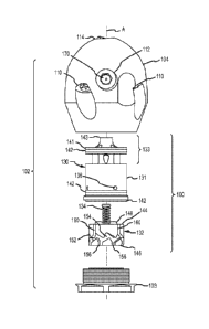
the
obstructions encountered. However, the forward directed jet tips produce a
counter
force against forward travel of the nozzle through the pipe. This counterforce

hinders effective deployment of the high pressure hose and reduces the net
pulling
force produced by the traction nozzle on the high pressure hose. Thus there is
a
need for a switching mechanism that does not generate a counterforce during
traction operation, yet facilitates operation of an effective fluid jet nozzle
during
actual cleaning operations. Furthermore, there is a need for a nozzle assembly

incorporating a switching valve assembly that is replaceable and has a minimum

number of component parts in order to simplify design and maintenance of such
a
nozzle assembly.
SUMMARY OF THE DISCLOSURE
[0002] An exemplary embodiment of a nozzle assembly in accordance with the
present disclosure includes a hollow nozzle head body containing a switching
valve
cartridge assembly captured in the body by an inlet nut fastened to the nozzle
body.
The cartridge assembly includes a generally cylindrical cartridge case
slidably
disposed in the nozzle body, a movable poppet disposed in the cartridge case,
and a
bias member resiliently biasing the poppet toward the inlet nut at a rear end
of the
cartridge case.
[0003] This nozzle assembly more particularly includes a hollow nozzle body
having a central bore and a plurality of ports extending through the body from
the
central bore. A switching valve cartridge is disposed in the central bore.
This
cartridge is operable to direct fluid flow from an inlet to at least one of
the plurality of
1

CA 02941243 2016-08-30
WO 2015/142460 PCT/US2015/016398
ports upon application of fluid flow above a predetermined threshold to the
inlet and
direct fluid flow from the inlet to at least a different one of the plurality
of ports upon
fluid flow having subsequently dropped below the predetermined threshold and
then
exceeding the predetermined threshold.
[0004] The cartridge includes a cylindrical cartridge case having a front
portion and
a cup shaped rear portion, a cylindrical poppet slidably disposed within the
cup
shaped rear portion of the cartridge case, and a biasing member within the
cartridge
case disposed between the front portion of the case and the poppet. This
biasing
member is preferably a coil spring. The spring urges the poppet away from the
front
portion of the cartridge case.
[0005] The cartridge preferably includes one or more of guide members engaging

the poppet to altematingly align the poppet with the at least one of the
plurality of
ports and the different one of the plurality of ports each time the poppet
abuts the
front portion of the case. The guide members are preferably pins through a
side wall
of the cartridge case projecting radially inward from the rear portion of the
cartridge
case that engage a corresponding feature on the poppet.
[0006] The poppet has at least one through bore to permit fluid flow
therethrough
and the corresponding feature. This feature preferably is a peripheral zig-zag

groove. Each transition below the predetermined threshold causes the poppet to

rotate about its axis to permit fluid flow to alternate between the first and
second set
of ports.
[0007] The front portion of the cartridge case has at least one bore
therethrough
leading to the first set of ports and at least one other bore therethrough
leading to the
second set of ports. The poppet has a front face and at least one lug
protruding from
the front face for selectively closing the at least one bore through the front
portion of
the cartridge case. The guide members rotate the poppet a predetermined
amount,
for example 22.5 each time the poppet moves toward or away from the front
portion
of the cartridge case.
[0008] The cartridge case preferably has two or more axial bores through the
front
portion equally spaced about a central axis through the cartridge case and two
or
more angled bores through the front portion extending to an annular channel
that
extends around the front portion of the cartridge case. The poppet has a front
face,
at least two through bores spaced about the central axis, and at least two
lugs
2

CA 02941243 2016-08-30
WO 2015/142460 PCT/US2015/016398
protruding from the front face for selectively engaging the axial and angled
bores
through the front portion of the cartridge case depending on a rotational
position of
the poppet within the rear portion of the cartridge case.
[0009] An embodiment of a nozzle assembly in accordance with the present
disclosure includes a hollow nozzle body connectable to a high pressure fluid
supply.
The nozzle body has a central bore, a first plurality of ports extending out
of the body
from one end of the central bore and a second plurality of ports extending out
of the
body from a side of the central bore. A switching valve cartridge assembly is
disposed in the central bore that is operable to direct fluid flow from an
inlet to one or
more of the first plurality of ports upon application of fluid flow above a
predetermined threshold to the inlet and direct fluid flow from the inlet to
one or more
of the second plurality of ports upon fluid flow dropping below the
predetermined
threshold and then exceeding the predetermined threshold again.
[0010] The cartridge assembly in this embodiment includes a cartridge case
disposed in the central bore of the hollow body. The cartridge case has a
front
portion and a cup shaped rear portion. The front portion has a first plurality
of bores
therethrough for passage of fluid to the first plurality of ports and a second
plurality of
bores therethrough for passage of fluid to the second plurality of ports.
[0011] A cylindrical poppet is slidably disposed in the rear portion of the
cartridge
case. This poppet has a plurality of axially extending poppet bores
therethrough. A
biasing member within the rear portion of the cartridge case extending between
the
front portion and the poppet urges the poppet away from the front portion of
the
cartridge case such that, absent fluid flow through the nozzle assembly, the
poppet
abuts against a retaining nut that captures the cartridge within the nozzle
body. A
guide member that extends between the rear portion of the cartridge case and
the
poppet engages a corresponding feature on the poppet to rotate the poppet as
it
slides forward and rearward within the rear portion of the cartridge case.
[0012] The poppet has a front face and a plurality of lugs protruding from the
front
face each closing one of the bores through the cartridge case when the poppet
abuts
against front portion of the cartridge case. The poppet has a zig-zag
peripheral
annular groove engaging the guide member. This engagement causes the poppet to

rotate in only one direction a predetermined amount about a central axis
through the
assembly each time fluid flow transitions above and below the predetermined
3

CA 02941243 2016-08-30
WO 2015/142460 PCT/US2015/016398
threshold. The bores through the poppet align with one or more of the bores
through
the cartridge case when the poppet abuts against the front portion of the
cartridge
case.
[0013] One embodiment of a switching valve cartridge for use in a nozzle body
in
accordance with the present disclosure includes a generally tubular cartridge
case
having a front portion and a cup shaped rear portion. The front portion has a
peripheral annular channel and a first plurality of axial bores therethrough
for axial
passage of fluid out of the front end and a second plurality of bores
therethrough for
passage of fluid to the annular channel. The cartridge also includes a
cylindrical
poppet slidably disposed in the rear portion of the cartridge case. This
poppet has a
plurality of axially extending poppet bores therethrough. A
biasing member is
disposed within the rear portion of the cartridge case between the front
portion and
the poppet. This biasing member is preferably a coil spring that biases the
poppet
away from the front portion of the cartridge case absent sufficient fluid flow
to
overcome the spring force. A guide member extends between the rear portion of
the
cartridge case and the poppet and engages a corresponding feature on the
poppet
to rotate the poppet as it slides forward and rearward within the rear portion
of the
cartridge case.
[0014] The poppet has a front face and a plurality of lugs protruding from the
front
face each closing one of the bores through the cartridge case when the poppet
abuts
against front portion of the cartridge case. The bores through the poppet
align with
one or more of the bores through the cartridge case when the poppet abuts
against
the front portion of the cartridge case.
[0015] Further features, advantages and characteristics of the embodiments of
this
disclosure will be apparent from reading the following detailed description
when
taken in conjunction with the drawing figures.
DESCRIPTION OF THE DRAWINGS
[0016] FIG. 1 is a partial exploded view of a switching nozzle head assembly
in
accordance with present disclosure fastened to a cleaning hose.
[0017] FIG. 2 is an enlarged exploded view of the switching nozzle head
assembly
shown in FIG. 1.
4

CA 02941243 2016-08-30
WO 2015/142460 PCT/US2015/016398
[0018] FIG. 3 is an axial cross sectional view through an assembled switching
nozzle head assembly in an unpressurized condition.
[0019] FIG. 4 is an axial cross sectional view through the nozzle head
assembly
shown in FIG. 3 in a pressurized condition with flow directed to cleaning
ports.
[0020] FIG. 5 is an axial cross sectional view through the nozzle head
assembly
rotated 45 degrees from that shown in FIGS. 3 and 4, with the poppet directing
flow
to tractor ports.
[0021] FIG. 6 is an axial cross sectional view through the nozzle assembly as
in
FIG. 4 with flow plugged from passage to the cleaning ports.
[0022] FIG. 7 is an axial cross sectional view through the nozzle assembly as
in
FIG. 5, showing the poppet preventing fluid flow to the tractor ports.
DETAILED DESCRIPTION
[0023] An exemplary embodiment of a nozzle assembly incorporating a switching
valve assembly is shown in Figures 1 through 7. Note that the cross sectional
views
of FIGS. 3, 4 and 6 are axial cross sectional views showing the cleaning
nozzle ports
passing out of the side of the nozzle head body. FIGS. 5 and 7 are axial cross

sectional views of the same assembly rotated 45 degrees, with the cut going
through
a pair of tractor nozzle ports.
[0024] Turning now to FIG. 1, a partial exploded view of a pipe cleaning
assembly
with a nozzle assembly 102 incorporating a cartridge assembly 100 in
accordance
with an exemplary embodiment of the present disclosure is shown. The nozzle
assembly 102 includes a hollow nozzle head body 104 that houses the cartridge
assembly 100 captured within the nozzle body 104 by a threaded retainer nut
103.
The assembly 102 is in turn threaded or otherwise fastened via retainer nut
103 to a
distal end of a rotating bearing coupling assembly 106 such as is disclosed in
US
Patent No. 6,059,202, which is, in turn, fastened to the distal end of a high
pressure
fluid hose 108.
[0025] A separate enlarged exploded view of the nozzle assembly 102 is shown
in
an exploded view in FIG. 2. The cartridge assembly 100 comprises a cartridge
body
130, a coil spring 134 and a poppet 132.

CA 02941243 2016-08-30
WO 2015/142460 PCT/US2015/016398
[0026] The nozzle head, or body, 104 in this exemplary embodiment, is
generally
symmetrical about its longitudinal axis "A" and has a set of four
circumferentially
spaced apart tractor ports 110, a set of four cleaning ports 112, and a front
cleaning
port 114. Each of these ports 110, 112, and 114 passes into a central blind
bore 116
into which the cartridge 100 is installed. The ports 110 and 114 extend into a
bottom
annulus portion of the central blind bore 116. The ports 112 intersect a side
portion
of the central blind bore 116, spaced from the bottom annulus portion of the
central
blind bore 116.
[0027] Each of these ports is positioned/directed at an angle from, or
displaced off
center from the longitudinal axis A of the nozzle body 104 so as to impart a
rotational
moment to the nozzle body 104 during device operation. The angle from the axis

causes forward traction, or neutral (no pulling), or retarding in the case of
a forward
cutting nozzle. It is only the radial offset that imparts a rotational moment
to the
nozzle body. As a result, during operation of the cartridge assembly 100, the
nozzle
body 104 spins on the bearing assembly 106. The bearing assembly 106 typically
is
designed to allow spinning of the nozzle assembly 102 at a controlled rate.
[0028] The choice of and direction of ports 110, 112, and 114 may be modified
in
different nozzle heads 104, depending on the particular cleaning application
for
which the nozzle assembly 102 is designed. For example, the precise angular
position, number and offset of each of the ports may be changed as well as the

number of sets of ports depending on operational needs for a specific
application.
Provided the same radial spacing of the port openings into the central blind
bore 116
remains the same, a variety of nozzle head configurations may utilize the same

cartridge 100 as described below. Furthermore, all of the wear parts in the
switching
valve mechanism of the nozzle assembly 102 are contained in the cartridge 100
such that repair is simplified by simple cartridge replacement when required.
[0029] The cartridge 100 comprises a cup shaped cartridge case 130, a poppet
132, and a biasing spring 134. The cartridge 100 is assembled into the central
blind
bore 116 in the nozzle body 104 and captured therein via the threaded retainer
nut
103. The threaded retainer nut 103 has a peripheral face groove holding a seal
0-
ring 142 which engages a rear annular face of the cartridge case 130 to
capture the
cartridge case 130 within the nozzle body 104. The cartridge case 130 carries
a pair
6

CA 02941243 2016-08-30
WO 2015/142460 PCT/US2015/016398
of spaced 0-rings 142 in corresponding peripheral grooves to center and seal
the
cartridge 100 in place in the bore 116.
[0030] The cartridge case 130 has a cup shaped rear portion 131 and a solid
front
portion 133. The front portion 133 has a distal end 143 for engaging the
bottom of
the central blind bore 116 in the nozzle body 104, an annular rim 141, and an
annular channel 140 around the front portion 133 separating the front portion
133
from the rear portion 131. The front portion 133 also has a central axial
blind bore
135 for receiving therein one end of the spring 134. The front portion 133
also
preferably has four axially extending, equally spaced apart bores 137
alternating with
four angled bores 139. The four axially extending bores 137 are symmetrically
spaced 90 degrees apart about the central axis A. The angled bores 139, also
90
degrees apart, are symmetrically spaced between the four axially extending
bores
137. Thus there is a bore 137 or 139 every 45 degrees around the central axis
A
through the cartridge case 130.
[0031] Each of these angled bores 137 communicates with the annular channel
140 around the solid front portion 133 of the cartridge case 130. The disc
shaped rim
141 of the front portion 133 carries an 0-ring 142 that isolates the annular
channel
156 from the distal end 143. The cartridge case 130 also has four equally
spaced
guide pins 136 that extend radially inward through the side wall of the cup
shaped
rear portion 131. These guide pins are press fit through the side wall of the
rear
portion 131, and are used to control position of the poppet 132 within the
cartridge
case 130 as explained further below. The cartridge case 130 requires no
specific
orientation about axis A when installed within the blind bore 116 of the
nozzle body
104.
[0032] The poppet 132 is basically a solid cylindrical body having a front end
144
and a rear end 146. The front end 144 has a flat radial face with four
symmetrically
spaced protruding lugs 148 spaced 90 degrees radially apart about the axis A.
Between these lugs 148 are four equally spaced axially extending through bores

150, again equally spaced 90 degrees apart about the axis A. Each of the lugs
148
acts as a valve disk to one of the bores 137 and 139 depending on the
rotational
position of the poppet 132 within the cartridge case 130.
7

CA 02941243 2016-08-30
WO 2015/142460 PCT/US2015/016398
[0033] The exemplary poppet 132 has an outer side wall 152 that has a zig-zag
pattern annular cam groove 154 formed in the side wall 152 fully around the
periphery of the poppet 132. This cam groove 154 is sized complementary to the

diameter and depth of the pins 136 that project radially inward from the side
wall of
the rear portion 131 of the cartridge case 130. When the cartridge 100 is
fully
assembled, the pins 136 ride in the cam groove 154. This cam groove 154 has
forward notches or vertices 156 each rotationally spaced about 450 apart along
the
groove 154. The cam groove 154 also has rear notches 158 spaced alternatingly
with four axial grooves 160 spaced about 900 apart. These axial grooves 160
merge
with the cam groove 154 at an angular rotation position between the rear
notches
158 in the groove 154.
[0034] Each of the four guide pins 136 ride in the cam groove 154 when the
valve
cartridge 100 is fully assembled. The sides of the cam groove 154 are angled
toward the sequential forward and rear notches or vertices 156 and 158 of the
groove 154 such that when the poppet 132 moves forward and back as flow is
applied or reduced, the poppet 132 has to rotate about 22.5 clockwise each
time as
it moves either forward or back with each change in flow above and below a
predetermined threshold rate.
[0035] When fluid flow is off, as is shown in FIG. 3, or at least reduced
below the
predetermined threshold, determined by the spring rate of the spring 134, the
poppet
132 is pushed by the spring 134 rearward so that it rests against the nut 103.
At the
same time, the poppet 132 is rotated 22.5 clockwise. The guide pins 136
shown in
FIG. 3 are either resting against the forward notches 156 or riding within the
axial
grooves 160.
[0036] In this intermediate position, the poppet 132 rests against the nut
103. In
this position, the passages 150 through the poppet 132 are open to all the
passages
in the cartridge case 130, i.e. the axial passages 137 and angled passages 139
to all
the ports 110, 112 and 114. However, fluid pressure is either off or low at
this point.
[0037] If the position of the poppet 132 before flow decrease had been as
shown in
FIG. 4, i.e., with flow through the angled passages 139 to the annular channel
140 to
the cleaning nozzle ports 112, then, when fluid flow is again turned on, the
poppet
132 again is moved forward by the fluid flow against the inlet end portion of
the
8

CA 02941243 2016-08-30
WO 2015/142460 PCT/US2015/016398
poppet 132, but this time moves the poppet 132 moves forward and rotates 22.5

clockwise to the position shown in FIG. 5. In this position, the passages 150
are
aligned with the axial passages 137 to the tractor ports 110 and front
cleaning port
114. At the same time, the four lugs 148 on the poppet end 144 close the four
angled bores 139 to the cleaning nozzles 112, as is shown in FIG. 6.
[0038] When flow is subsequently reduced below the predetermined threshold,
such as by the operator turning off flow, the poppet 132 rotates about 22.5
as the
spring 134 pushes the poppet 132 rearward, via engagement with the stationary
guide pins 136 to cause rotation and axial movement to an intermediate
position,
again as is shown in FIG. 3, except rotated one notch 156 further by 22.5 .
This
rotation is caused by the interaction between the stationary guide pins 136
riding in
the groove 154 forcing rotation of the poppet 132 as the spring 134 pushes the

poppet rearward.
[0039] Then, when flow is again increased above the predetermined threshold,
the
poppet 132 rotates about 22.5 again as fluid flow pushes the poppet 132
forward, to
the position shown in FIGS. 4 and 7. When the poppet 132 is in this position,
the
passages 137 are plugged via the lugs 148, and the passages 150 are directly
aligned with the angled bores 139 to the annular channel 140 and the cleaning
ports
112. Since the ports 137 are plugged as is shown in FIG. 7, there is no flow
available
to the traction ports 110. Thus, while flow is directed through the cleaning
ports 112,
flow is positively prevented through the traction ports 110.
[0040] Each cycle of fluid flow/pressure application causes about a 45
rotation of
the poppet 132 and hence an alternation between fluid flow being directed to
forward
port 114 and traction ports 110 and between cleaning ports 112. Since all of
these
ports are preferably offset from a direct radial orientation, a rotational
torque is
applied to the nozzle body 104 to cause nozzle head rotation when fluid
pressure is
applied. Finally, each of the ports 110, 112 and 114 each preferably has a
threaded
jet tip 170 installed. These jet tips 170 may also be of different
configurations
depending on the task to be performed.
[0041] It is to be understood that various changes can be made to the nozzle
body
104 and to the switching valve cartridge 100 in accordance with the present
disclosure. For example, the nozzle head body 104 may be configured with a
9

CA 02941243 2016-08-30
different number of ports 110 and 112 and the corresponding poppet 132 and
case
130 in the cartridge 100 would thus have a different number of openings and
passages. The same cartridge 100 may be utilized in a variety of nozzle head
bodies 104 each with a different set of angled ports. The angles and offsets
utilized
may be tuned to achieve specific rotational torques at designed pressures and
flow
rates. Additionally, the lugs 148 on the poppet 132 may be replaced with a
flat face
seal. The cartridge 100 could also be used in a non-rotary nozzle or flow
diversion
design in-line along a hose.
[0042] The scope of the
claims should not be limited by the preferred
embodiments set forth in the examples, but should be given the broadest
interpretation consistent with the description as a whole.

Representative Drawing
A single figure which represents the drawing illustrating the invention.
Administrative Status

For a clearer understanding of the status of the application/patent presented on this page, the site Disclaimer , as well as the definitions for Patent , Administrative Status , Maintenance Fee  and Payment History  should be consulted.

Administrative Status

Title Date
Forecasted Issue Date 2018-10-16
(86) PCT Filing Date 2015-02-18
(87) PCT Publication Date 2015-09-24
(85) National Entry 2016-08-30
Examination Requested 2016-08-30
(45) Issued 2018-10-16

Abandonment History

There is no abandonment history.

Maintenance Fee

Last Payment of $210.51 was received on 2023-12-07


 Upcoming maintenance fee amounts

Description Date Amount
Next Payment if small entity fee 2025-02-18 $125.00
Next Payment if standard fee 2025-02-18 $347.00

Note : If the full payment has not been received on or before the date indicated, a further fee may be required which may be one of the following

  • the reinstatement fee;
  • the late payment fee; or
  • additional fee to reverse deemed expiry.

Patent fees are adjusted on the 1st of January every year. The amounts above are the current amounts if received by December 31 of the current year.
Please refer to the CIPO Patent Fees web page to see all current fee amounts.

Payment History

Fee Type Anniversary Year Due Date Amount Paid Paid Date
Request for Examination $800.00 2016-08-30
Application Fee $400.00 2016-08-30
Maintenance Fee - Application - New Act 2 2017-02-20 $100.00 2017-02-17
Maintenance Fee - Application - New Act 3 2018-02-19 $100.00 2018-02-09
Final Fee $300.00 2018-09-04
Maintenance Fee - Patent - New Act 4 2019-02-18 $100.00 2019-01-23
Maintenance Fee - Patent - New Act 5 2020-02-18 $200.00 2020-01-29
Maintenance Fee - Patent - New Act 6 2021-02-18 $200.00 2020-12-22
Maintenance Fee - Patent - New Act 7 2022-02-18 $204.00 2021-12-31
Maintenance Fee - Patent - New Act 8 2023-02-20 $203.59 2022-12-14
Maintenance Fee - Patent - New Act 9 2024-02-19 $210.51 2023-12-07
Owners on Record

Note: Records showing the ownership history in alphabetical order.

Current Owners on Record
STONEAGE, INC.
Past Owners on Record
None
Past Owners that do not appear in the "Owners on Record" listing will appear in other documentation within the application.
Documents

To view selected files, please enter reCAPTCHA code :


To view images, click a link in the Document Description column. To download the documents, select one or more checkboxes in the first column and then click the "Download Selected in PDF format (Zip Archive)" or the "Download Selected as Single PDF" button.

List of published and non-published patent-specific documents on the CPD .

If you have any difficulty accessing content, you can call the Client Service Centre at 1-866-997-1936 or send them an e-mail at CIPO Client Service Centre.


Document
Description 
Date
(yyyy-mm-dd) 
Number of pages   Size of Image (KB) 
Abstract 2016-08-30 2 80
Drawings 2016-08-30 7 242
Representative Drawing 2016-08-30 1 33
Cover Page 2016-09-27 1 52
Examiner Requisition 2017-08-10 5 235
Amendment 2018-01-31 15 514
Maintenance Fee Payment 2018-02-09 1 33
Claims 2018-01-31 9 376
Claims 2016-08-30 6 236
Description 2016-08-30 10 519
Change of Agent 2018-08-27 1 34
Office Letter 2018-09-04 1 30
Final Fee 2018-09-04 1 40
Change of Agent 2018-09-05 3 76
Office Letter 2018-09-19 1 25
Representative Drawing 2018-09-20 1 10
Cover Page 2018-09-20 1 47
International Search Report 2016-08-30 2 96
Declaration 2016-08-30 3 39
National Entry Request 2016-08-30 7 162
Maintenance Fee Payment 2017-02-17 1 33