Note: Descriptions are shown in the official language in which they were submitted.
SYSTEMS AND METHODS FOR PREVENTING ROTATION OF ROTOR BEARINGS
IN A STATOR
BACKGROUND
[0001/2] Field of the invention.
[0003] The invention relates generally to rotor bearings, and more
particularly to
systems and methods for preventing rotor bearings from rotating within a
stator, where it is
not necessary to precisely align the bearings for installation in the stator.
[0004] Related art.
[0005] Oil and natural gas are often produced by drilling wells into oil
reservoirs and
then pumping the oil and gas out of the reservoirs through the wells. If there
is insufficient
pressure in the well to force these fluids out of the well, it may be
necessary to use an
artificial lift system in order to extract the fluids from the reservoirs. A
typical artificial lift
system employs an electric submersible pump which is positioned in a producing
zone of the
well to pump the fluids out of the well.
[0006] An electric submersible pump system includes a pump and a motor which
is
coupled to the pump and drives the pump. The electric submersible pump system
may also
include seals, gauge packages and other components. Because they are designed
to fit within
the borehole of a well, electric submersible pump systems are typically less
than ten inches
wide, but may be tens of meters long. The motor of an electric submersible
pump system
may produce hundreds of horsepower.
[0007] The motor of the electric submersible pump system is typically an AC
induction motor. The motor has a stator that is cylindrical with a coaxial
bore. A rotor (or
more than one rotor) is coaxially positioned within the bore of the stator.
The rotor is
coupled to a shaft so that rotation of the rotor turns the shaft. Bearings
hold the shaft, hence
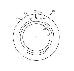
the rotor, in position within the bore of the stator and allow the shaft and
rotor to rotate
smoothly within the bore.
[0008] Conventionally, each bearing is held in position within the stator bore
by one
or more T-rings. The T-rings are seated in a nesting groove around the
periphery (the
cylindrical outer surface) of the bearing. The T-rings extend radially outward
from the
CA 2941247 2018-01-04
CA 02941247 2016-08-30
WO 2015/134236 PCT/US2015/017282
bearing and contact the inner diameter of the stator bore. The T-rings thereby
provide an
interference fit between the bearing and the stator which serves to prevent
the bearings from
rotating in the stator bore, while also allowing the bearings to move axially
within the stator
bore to account for thermal expansion of the rotor stack. Such rotation of the
bearings will
cause unnecessary wear and/or damage to the bearings or the stator, which may
lead to rapid
motor failure.
[0009] There are, however, some disadvantages to using T-rings to hold the
bearings
within the stator. T-rings are commonly made from an elastomeric material such
as EPDM,
or ethylene propylene diene monomer. These types of elastomeric materials may
not be able
to withstand the high temperatures that are experienced by motors in downhole
environments.
In particular, in SAGD (steam assist, gravity drain) applications that are
used to get oil out of
tar sands, the downhole temperatures typically exceed 200 C. At these
temperatures, EPDM
loses its mechanical integrity and fails, so that the T-rings are no longer
capable of properly
securing the bearings and preventing them from rotating within the stator
bore.
[0010] It would therefore be desirable to provide a mechanism for securing the
bearings, and particularly for preventing the bearings from rotating in the
stator bore while
allowing axial bearing movement to account for thermal expansion, where the
new
mechanism does not fail in the high temperatures of downhole environments.
SUMMARY OF THE INVENTION
[0011] This disclosure is directed to systems and methods for preventing
rotation of
rotor bearings in electric motors which enable retrofitting of conventionally
designed
bearings to use spring-loaded keys instead of elastomeric T-rings to prevent
rotation of the
bearings within a stator bore. An elongated, curved spring arm is positioned
in the nesting
groove at the outer periphery of the bearing. One end of the spring may be
secured to the
bearing by positioning an S-shaped bend in the spring arm through a hole in
the floor of the
nesting groove. A key at the opposite end of the spring arm is urged radially
outward by the
spring arm. The key may be positioned in a slot in the outer portion of the
bearing, and the
spring arm may be retained in the groove by a retaining pin installed in the
groove. The key
moves radially as the spring arm is flexed. The key is pushed radially inward
to a position
that is within the outer diameter of the bearing. This allows the bearing to
be inserted into the
stator bore without the key having to be aligned with a keyway of the stator.
After the
bearing has been inserted into the stator bore (typically when the motor is
operated), the
bearing may rotate until the key at the end of the spring arm is aligned with
the keyway in the
2
CA 02941247 2016-08-30
WO 2015/134236 PCT/US2015/017282
stator bore. When the key is aligned with the keyway, the key is urged
radially outward by
the spring arm into the keyway, preventing further rotation of the bearing in
the stator.
[0012] One embodiment comprises an apparatus having a rotor bearing with a
spring/key mechanism installed in a nesting groove at the outer periphery of
the bearing. The
spring/key mechanism includes a curved spring arm that fits within the nesting
groove. The
spring arm has a first end that is secured to the bearing and resists
circumferential movement
of the spring arm with in the nesting groove. This may be accomplished, for
example, by
providing an S-shaped bend at the end of the spring arm and positioning the S-
shaped bend
through a hole that is formed in the floor of the groove. Alternatively, the
spring arm may be
long enough that it extends around more than half of the circumference of the
groove and
simply clips onto the bearing. A retaining pin may be provided to hold the
spring arm in
position within the groove. At the opposite end of the spring arm is a key. At
least a portion
of this end of the spring arm has a radius of curvature that is greater than
that of the groove,
so that the spring arm urges the key radially outward from the groove. This
causes the key to
move into engagement with a corresponding keyway of the stator when the
bearing is
positioned in the stator bore and rotates to move the key into alignment with
the keyway.
[0013] The spring/key mechanism may be formed in various ways. In one
embodiment, a round wire is formed into the curved arc of the spring arm. An S-
shaped bend
is made in one end of the wire for securing the spring arm to the bearing. A C-
shaped bend is
made in the other end of the wire to form the key. The spring/key mechanism
may
alternatively be made from flat wire. In one embodiment, an S-shaped bend is
made in one
end of the wire to be positioned in the hole in the floor of the nesting
groove. The other end
of the flat wire is bent upward to form the key. The key may be narrow enough
to fit within
the nesting groove, or it may be wider than the groove, in which case a slot
is formed in the
outer portion of the bearing to accommodate the key. The edges of the key may
be rounded
or chamfered to facilitate depression of the key into the groove and/or slot
upon installation
of the bearing into the stator bore.
[0014] An alternative embodiment comprises a method for retrofitting a rotor
bearing
with a mechanism that prevents rotation of the bearing within a stator. This
method includes
providing a conventionally designed bearing, possibly making minor
modifications to the
bearing, and installing a spring/key mechanism on the bearing. If the bearing
initially has a
T-ring installed in the nesting groove at the outer periphery of the bearing,
the T-ring is
removed. Depending upon the design of the spring/key mechanism, it may be
necessary to
form a slot in the outer portion of the bearing. Holes may be formed in the
floor and/or walls
3
of the groove to accept an S-shaped bend in the end of the spring arm, and to
allow
installation of a retaining pin. The spring arm of the spring/key mechanism is
then installed
by inserting the S-shaped bend through the hole in the floor of the groove and
positioning the
curved spring arm in the nesting groove. This deforms the spring arm so that a
spring force
will be applied to the key to urge it radially outward from the bearing. The
spring arm may
be retained in the groove by installing a retaining pin over it.
[0014a] Another alternative embodiment comprises an apparatus comprising: a
rotor
bearing having a nesting groove in an outer periphery of the rotor bearing,
wherein the
nesting groove extends in a circumferential direction and extends in an arc of
at least 30
degrees around an axis of the bearing; a curved spring arm positioned in the
nesting groove,
wherein the spring arm extends in an are of at least 30 degrees around the
axis of the bearing,
wherein the spring arm has a first end that is secured to the bearing and
resists circumferential
movement of the spring arm with respect to the bearing, wherein the spring arm
has a second
end opposite the first end, wherein the spring arm has a key connected to the
second end, and
wherein when the key is positioned within an outer diameter of the bearing,
the spring arm is
deformed against a floor of the nesting groove and thereby provides a spring
force that urges
the key radially outward from the bearing; and a stator, wherein the stator
has a bore
therethrough, wherein the bore has a keyway therein, wherein the rotor bearing
is positioned
within the bore and the key is urged by the spring arm into contact with the
stator, and
wherein when the key is aligned with the keyway, the key is urged into the
keyway by the
spring arm.
[0014b] A further alternative embodiment comprises a method for retrofitting a
rotor
bearing with a mechanism that prevents rotation of the bearing within a
stator, the method
comprising: providing a bearing having a nesting groove in an outer periphery
of the bearing,
wherein the nesting groove extends in a circumferential direction and extends
in an arc of at
least 30 degrees around an axis of the bearing; providing a spring/key member
that includes a
curved spring arm and a key, wherein the spring arm forms an arc of between 30
and 360
degrees around the axis of the bearing between first and second ends of the
spring arm;
installing the spring/key member in the nesting groove, wherein the spring arm
provides a
spring force between a floor of the nesting groove and the key which urges the
key radially
outward from the bearing; and installing the bearing in a bore of a stator,
wherein the bore
has a keyway therein, wherein when the key is aligned with the keyway, the key
is urged into
the keyway by the spring arm.
[0015] Numerous other embodiments are also possible.
4
CA 2941247 2018-01-04
BRIEF DESCRIPTION OF THE DRAWINGS
[0016] Other objects and advantages of the invention may become apparent upon
reading the following detailed description and upon reference to the
accompanying drawings.
[0017] FIGURE 1 is a diagram illustrating some of the primary components of an
electric submersible pump system.
[0018] FIGURE 2 is a diagram illustrating the structure of an exemplary motor
suitable for use in an electric submersible pump system.
[0019] FIGURE 3 is a more detailed diagram illustrating the structure of an
exemplary motor including a rotor bearing.
[0020] FIGURES 4A and 4B are diagrams illustrating an exemplary rotor bearing
in
accordance with the prior art.
[0021] FIGURES 5A and 5B are diagrams illustrating an exemplary rotor bearing
having a spring-loaded key installed thereon in accordance with one
embodiment.
[0022] FIGURE 6 is a diagram illustrating a spring/key member in accordance
with
one embodiment.
[0023] FIGURES 7A and 7B arc a pair of diagrams illustrating the operation of
the
spring/key member in one embodiment.
[0024] FIGURES 8A-8C are diagrams illustrating spring/key members in
accordance
with several alternative embodiments.
[0025] FIGURES 9A-9B are diagrams illustrating interlocking keys and spring
arm
ends in accordance with two alternative embodiments.
[0026] While the invention is subject to various modifications and alternative
forms,
specific embodiments thereof are shown by way of example in the drawings and
the
accompanying detailed description. It should be understood, however, that the
drawings and
detailed description are not intended to limit the invention to the particular
embodiment
which is described. This disclosure is instead intended to cover all
modifications, equivalents
4a
CA 2941247 2018-01-04
CA 02941247 2016-08-30
WO 2015/134236 PCT/US2015/017282
and alternatives falling within the scope of the present invention. Further,
the drawings may
not be to scale, and may exaggerate one or more components in order to
facilitate an
understanding of the various features described herein.
DESCRIPTION OF EXEMPLARY EMBODIMENTS
[0027] Various embodiments of the invention are described below. It should be
noted
that these and any other embodiments described below are exemplary and are
intended to be
illustrative of the invention rather than limiting.
[0028] As described herein, various embodiments of the invention comprise
systems
and methods for preventing rotation of rotor bearings in electric motors. In
one embodiment,
an elongated spring arm is positioned near the outer diameter of the bearing
so that it extends
around at least a portion of the outer periphery of the bearing. There is a
tab or key at one
end of the spring arm. The key moves radially as the spring is flexed. As the
key is pushed
radially inward, the spring arm is compressed. This moves the key to a
position within the
outer diameter of the bearing, allowing the bearing to be inserted into the
stator bore without
the key having to be aligned with a keyway of the stator. After the bearing
has been inserted
into the stator bore, the bearing rotates until the key at the end of the
spring arm is aligned
with the keyway in the stator bore. When the key is aligned with the keyway,
the key is
urged radially outward by the spring arm into the keyway, preventing further
rotation of the
bearing in the stator.
[0029] The particular design of the spring arm and key may vary from one
embodiment to another. The various embodiments may provide several advantages
over the
prior art. For instance, many bearing designs cannot be easily modified to
accommodate
conventional coil-spring-loaded keys, but very little modification of these
designs is
necessary to allow them to be retrofitted with the present spring-arm key
mechanism.
Additionally, the force provided by the circumferentially positioned spring
arm to urge the
key radially outward is more constant across the travel of the key and greater
when the key is
extended into the stator's keyway, when compared to a conventionally
positioned coil spring.
The spring arm therefore more effectively ensures that the key will engage the
keyway.
[0030] Embodiments of the invention may be implemented, for example, in
electric
submersible pump systems. It should be noted that the invention is not limited
to electric
submersible pumps, but can be implemented in other types of motors as well.
The electric
submersible pump motor described herein is intended to be exemplary of the
motors in which
the invention can be used.
CA 02941247 2016-08-30
WO 2015/134236 PCT/US2015/017282
[0031] Referring to FIGURE 1, a diagram illustrating the components of an
electric
submersible pump system in one embodiment is shown. In this embodiment, an
electric
submersible pump system is implemented in a well for producing oil, gas or
other fluids. An
electric submersible pump system 120 is coupled to the end of tubing string
150, and the
electric submersible pump system and tubing string are lowered into the
wellbore to position
the pump in a producing portion of the well. A drive system (not shown) at the
surface of the
well provides power to the electric submersible pump system 120 to drive the
system's
motor.
[0032] Electric submersible pump system 120 includes a pump section 121, a
seal
section 122, and a motor section 123. Electric submersible pump system 120 may
include
various other components which will not be described in detail here because
they are well
known in the art and are not important to a discussion of the invention. Motor
section 123 is
coupled by a shaft through seal section 122 to pump section 121. Motor section
123 rotates
the shaft, thereby driving pump section 121, which pumps the oil or other
fluid through the
tubing string 150 and out of the well.
[0033] Referring to FIGURE 2, a diagram illustrating the structure of an
exemplary
motor suitable for use in an electric submersible pump system is shown. As
depicted in this
figure, motor 200 has a stator 210 and a rotor 220. Stator 210 is generally
cylindrical, with a
coaxial bore that runs through it. Rotor 220 is coaxially positioned within
the bore of stator
210. Rotor 220 is attached to a shaft 230 that is coaxial with the rotor and
stator 210. In this
example, rotor 220 includes multiple sections (e.g., 221), where bearings
(e.g., 240) are
positioned at the ends of each section. The bearings 240 support shaft 230,
and consequently
rotor 220, within the bore of stator 210 and allow the rotor and shaft 230 to
rotate within the
stator.
[0034] Referring to FIGURES 3 and 4, a pair of diagrams illustrating the
structure of
motor 200 and one of the bearings of the motor are shown in more detail. It
can be seen in
this figure that stator 210 is formed by stacking a set of thin, substantially
identical plates or
laminations (e.g., 311). The laminations 311 are generally annular in shape,
so that when
they are stacked together, they form a generally cylindrical shape, with a
coaxial, cylindrical
bore in the center. The diameter of the bore of the stator 210 may also be
referred to as the
inner diameter of the stator. The stacked laminations 311 are pressed into a
housing 312 to
form the stator assembly 210. It should be noted that the laminations 311 need
not be exactly
identical. Similarly, the laminations 311 need not be perfectly annular. For
example, in
some embodiments, the laminations form a key or keyway that extends axially
and mates
6
CA 02941247 2016-08-30
WO 2015/134236 PCT/US2015/017282
with a corresponding structure of housing 312 to prevent the stacked
laminations from
rotating within the housing. Each of laminations 311 also includes a notch on
its inner
diameter. This notch enables the alignment of the lamination with the other
laminations in
the stator and also forms a part of the keyway that will be engaged by the
spring-loaded key
of the bearing.
[0035] The construction of rotor 220 is similar to that of stator 210, in that
the rotor
sections are formed by stacking corresponding sets of laminations (e.g., 321).
The
laminations 321 are again essentially annular, having an outer diameter that
is slightly less
than the inner diameter of stator 220, and an inner diameter that is
substantially equal to the
outer diameter of shaft 230. Each set of laminations 321 is stacked and shaft
230 is
positioned through the bore formed through the stacked rotor laminations. The
shaft 230 and
laminations 321 may be keyed to prevent the laminations from rotating with
respect to the
shaft.
[0036] Rotor 220 is held in position within stator 210 by the rotor bearings
(e.g., 240).
As noted above, there are multiple bearings, each of which is positioned
between (or at an
ends of) the rotor sections. Thrust washers (e.g., 360) are positioned between
bearing 240
and the end plates (e.g., 370) of the rotor sections. A sleeve 380 is secured
to shaft 230.
Bearing 240 has an inner portion 341 that supports sleeve 380 and allows the
sleeve to rotate
within the bearing. Inner portion 341 may also be referred to as the neck of
the bearing.
Bearing 240 has an outer portion 342 that extends radially outward toward the
stator.
Passageways (e.g., 343) through outer portion 342 allow oil to flow through
the outer portion,
facilitating lubrication and cooling of the motor components.
[0037] Bearing 240 is a conventional bearing that uses a T-ring (350) to
maintain the
position of the bearing within the stator bore. T-ring 350 is seated in a
nesting groove 344 in
the periphery of the outer portion (342) of the bearing. The outer diameter of
bearing 240 is
slightly less than the inner diameter of the stator bore, so T-ring 350
extends radially outward
from the outer diameter of the bearing in order to contact the inner diameter
of the stator. T-
ring 350 is intended to provide an interference fit between bearing 240 and
stator 210 to hold
the bearing in place within the stator bore and prevent the bearing from
rotating within the
stator bore. The interference fit allows axial movement of the bearing within
the stator bore
to accommodate movement of the stacked laminations of the rotor caused by
thermal
expansion during operation of the motor.
[0038] Referring to FIGURES 4A and 4B, bearing 240 is shown apart from the
other
components of the motor. FIGURE 4A is a view of the bearing along its axis,
while FIGURE
7
CA 02941247 2016-08-30
WO 2015/134236 PCT/US2015/017282
4B is a side view of the bearing. These figures explicitly depict the axis
(410) of the bearing,
as well as the outer diameter (420) of the bearing. Outer diameter 420 may
also be referred
to herein as the outer periphery of the bearing.
[0039] For purposes of this disclosure, the term "radially" refers to
directions that are
substantially (and not necessarily exactly) perpendicular to the axis of the
bearing. Thus,
"radially inward" means a direction toward the axis, while "radially outward"
means a
direction away from the axis. The term "circumferential" refers to directions
(or items)
having a substantially constant distance from the axis. For example, T-ring
350 extends
circumferentially around bearing 240.
[0040] FIGURES 5A and 5B illustrate a bearing that has a spring-loaded key
incorporated therein in accordance with one embodiment. In this embodiment,
the bearing
shown in FIGURES 4A and 4B has been modified to incorporate a spring loaded
key to
illustrate the manner in which a conventional bearing can be easily
retrofitted with the present
spring-loaded key mechanism.
[0041] Referring to FIGURES 5A and 5B, bearing 500 has a cylindrical inner
portion
510 and a cylindrical outer portion 520, with a bore therethrough. A plurality
of passageways
(e.g., 530) are provided through outer portion 520 to allow oil to circulate
through the
bearing. A nesting groove 540 is formed in the outer periphery 525 of the
bearing. These
features are common to the conventional bearing shown in FIGURES 4A and 4B.
[0042] Bearing 500, however, includes several features that are not found in
the
conventional bearing. For example, rather than having a T-ring positioned in
groove 540,
bearing 500 has a spring/key member 560 that is installed in the groove.
Spring/key member
560 has a curved body, or spring arm 561 that extends circumferentially around
a portion of
the groove. Spring arm 561 forms an arc of approximately 80 degrees, but could
be between
about 30 to 360 degrees in alternative embodiments. At a lower end of spring
body 561 is an
S-shaped bend 562. At the upper end of body 561 is a C-shaped key 564. The
diameter of
key 564 must be sized to fit in the keyway. A hole 542 is formed between the
bottom of
groove 540 and passageway 530. S-shaped bend 562 is positioned in hole 542 to
secure the
lower end of spring/key member 560. C-shaped key 564 is positioned in slot
550.
Spring/key member 560 is shown apart from the bearing in FIGURE 6.
[0043] Spring/key member 560 is preferably made of a non-magnetic metal, such
as
203/304 stainless steel, 17-7 stainless steel, or any grade of Inconel, Monel,
or Elgiloy.
Spring body 561 has a radius of curvature that is greater than the radius of
curvature of the
bottom or floor 544 of groove 540. Consequently, when S-shaped bend 562 is
secured in
8
CA 02941247 2016-08-30
WO 2015/134236 PCT/US2015/017282
hole 542 and C-shaped key 564 is positioned in slot 550, the C-shaped key is
urged radially
outward, away from the bearing. In one embodiment, a retaining pin 570 may be
positioned
over spring/key member 560 to retain the spring/key member in groove 540.
Retaining pin
570 is inserted into hole 571, which extends above and across groove 540 and
into the
opposing side of outer portion 520. In an alternative embodiment, as key 564
is urged
outward, it may actually move at an angle with respect to slot 550, so that
the key contacts
the side of the slot. This may limit the outward movement of the key and
thereby retain it in
the slot. In this case, there is no need for retaining pin 570.
[0044] Referring to FIGURES 7A and 7B, a pair of diagrams illustrating the
operation of the spring/key member is shown. These figures depict a bearing
having a
spring/key member as described in connection with FIGURES 5-6, where the
bearing has
been positioned within a stator bore. Each of FIGURES 7A and 7B shows the
outer portion
710 of the bearing and the bore of stator 720. Outer portion 710 of the
bearing has a slot 730
in which key 740 is positioned. FIGURE 7A shows key 740 in a retracted
position in slot
730 of the bearing, while FIGURE 7B shows the key in an extended position in
which it
engages keyway 750 of the stator.
[0045] When the bearing is installed in the stator, key 740 is simply pushed
down into
slot 730 so that it does not substantially extend beyond the outer diameter of
the bearing, and
the bearing is inserted into the stator bore without regard for the
circumferential orientation of
the bearing with respect to keyway 750. In most instances, slot 730 and key
740 will not be
aligned with keyway 750, so key 740 will initially remain in its retracted
position in slot 730,
as shown in FIGURE 7A. After the motor is assembled and it begins operating,
rotation of
the rotor within the stator will normally cause the bearing to rotate to some
degree. When the
rotation of the bearing brings key 740 into alignment with keyway 750, the
spring arm will
cause key 740 to move radially outward into the keyway. When key 740 engages
keyway
750 in this manner, the bearing is prevented from rotating any further in the
stator. The
diameter of the key 740 must be small enough relative to the groove to allow
axial movement
of the bearing in the stator, but large enough to transfer sufficient
rotational force to the
bearing to prevent bearing rotation.
[0046] As shown in FIGURES 5A and 5B, a portion of C-shaped key 564 is
positioned within slot 550. This configuration is advantageous in that the
rotating force is
immediately transferred from the keyway of the stator through the key to the
outer portion of
the bearing. In alternative embodiments, it is not necessary for the key to be
positioned in a
slot in the bearing. The key may instead sit entirely within the groove around
the periphery
9
CA 02941247 2016-08-30
WO 2015/134236 PCT/US2015/017282
of the bearing. In such a configuration, the rotating force would be
transferred from the stator
keyway, down the length of the spring arm to the S-shaped bend that is secured
to the
bearing. Similarly, it is not necessary in all embodiments to use the
mechanism of an S-
shaped bend in a hole in the bearing to hold the spring arm in position and
prevent it from
rotating (moving circumferentially with respect to the bearing). If the spring
arm is long
enough (e.g., if the spring arm extends 270 degrees around the groove), the
friction between
the spring arm and the bottom of the groove may be sufficient to hold the
spring arm in
position on the bearing and consequently to prevent the bearing from rotating
within the
stator.
[0047] The spring/key member described above in connection with FIGURES 5-6 is
an example of the many variations that are possible. Several alternative
embodiments of the
spring/key member are shown in FIGURES 8A-8C. FIGURE 8A shows an embodiment in
which spring/key member 810 is formed from round wire, similar to spring/key
member 560.
The C-shaped key (811) and S-shaped bend (813) of spring/key member 810 are
the same as
the corresponding components of member 560, but the body (812) of spring/key
member 810
is longer, and extends around a greater portion of the groove in the periphery
of the bearing
(forming an arc of approximately 170 degrees, instead of the approximately 80
degree arc of
spring/key member 560).
[0048] FIGURES 8B and 8C depict embodiments of the spring/key member that are
formed with flat wire, which has a substantially constant thickness and width,
instead of
round wire. In the embodiment of FIGURE 8B, a key 821 is formed at the upper
end of
spring body 822, and an S-shaped bend 823 is formed at the lower end. The
width of body
822 is small enough the body will be seated on the floor of the groove. Key
821, however, is
wider than the body, so that it will extend into the slot that is formed in
the outer portion of
the bearing. As explained above, this will result in the transfer of the
rotating force
immediately from the keyway of the stator through the key to the outer portion
of the bearing.
[0049] The embodiment of FIGURE 8C is very similar to that of FIGURE 8B,
having
a key 321 at the upper end of spring body 832, and an S-shaped bend 833 at the
lower end.
The embodiment of FIGURE 8C, however, does not have a widened key. Key 831 is
instead
the same width as spring body 832. Key 831 is narrow enough that it fits
entirely within the
nesting groove of the bearing. One of the advantages of this configuration is
that it is not
necessary to form a slot in the outer portion of the bearing. Additionally,
the spring/key
member itself uses less material and may be less costly to manufacture than
the design with
the wider key.
CA 02941247 2016-08-30
WO 2015/134236 PCT/US2015/017282
[0050] It can be seen that, in each of the embodiments shown in FIGURES 6 and
8A-
8C, the key has rounded or chamfered edges (e.g., 814, 824, 834) in order to
facilitate
installation into, and removal from, the motor bore. The rounded/chamfered
edges prevent
the edge of the key from catching on the edge of the stator bore and keep the
key pushed
down into the nesting groove as the bearing slides into the stator bore. The
chamfered edge
also allows for removal of the bearing from the stator, where the expanded
spring transitions
from the keyway into a smaller diameter exit bore. Lack of a chamfered edge
would
effectively create a snap lock where the key would deadhead against a smaller
diameter lead-
in bore to the stator, thus preventing the bearing, and thus potentially the
entire rotor stack,
from being pulled out of the stator.
[0051] Although each of the embodiments shown in FIGURES 6 and 8A-8C includes
an S-shaped bend to secure the lower end of the spring/key member to the
bearing (e.g., by
positioning it in hole 542), alternative embodiments may keep the device in
position using
alternative means. For instance, an L-shaped bend may be used instead of an S-
shaped bend.
The S-shaped or L-shaped bend could also be positioned in a hole through the
side of the
groove, rather than the floor of the groove, to secure the end of the spring
arm.
[0052] In other embodiments, the spring arm may be lengthened so that the
spring
arm wraps around the floor of the groove and holds the spring/key member on
the bearing.
The spring arm may, for example, form an arc of 270 degrees so that it clips
onto the bearing.
It may therefore be unnecessary to provide any means to secure the lower end
of the spring
arm to the bearing other than the spring arm itself In this embodiment, the
portion of the
spring arm that provides the friction fit on the bearing may have a radius of
curvature that is
less than that of the floor of the groove, while a portion adjacent to the key
may have a
greater radius of curvature so that it can provide a spring force to urge the
key outward from
the bearing.
[0053] In another embodiment, the spring arm may wrap entirely around the
bearing
so that one end of the spring arm hooks onto the other end. In this
embodiment, the spring
arm may be considered to form an arc of 360 degrees. Examples of this
embodiment are
depicted in FIGURES 9A-9B. In FIGURE 9A, a small T (910) is formed in the end
of the
spring arm opposite the key (920). A T-shaped hole (930) through key 920 is
provided so
that T 910 can be inserted through the widened upper part of hole 930. When T
910 is moved
downward into the narrower part of hole 930 (as shown in the figure), the T is
locked against
key 920. In the example of FIGURE 9A, a simpler 90-degree bend (940) is formed
at the end
11
CA 02941247 2016-08-30
WO 2015/134236 PCT/US2015/017282
of the spring arm. Bend 940 is inserted through a hole (950) that is formed in
the spring arm
just below key 960, holding the two ends of the spring arm together.
[0054] There may be other variations in other alternative embodiments. For
instance,
in one embodiment, the stator may include more than one keyway that can be
engaged by the
spring-loaded key. In another embodiment, multiple spring-loaded keys may be
installed on
a bearing. Some embodiments comprise the spring-loaded key mechanism alone,
while other
embodiments may include this mechanism installed on a bearing, and yet other
embodiments
comprise a motor having one or more bearings with the spring-loaded key
mechanism.
[0055] Another alternative embodiment comprises a method for retrofitting a
rotor
bearing. In this method, a bearing that is designed to be used with a
conventional T-ring is
retrofitted with a spring/key member as described above. The retrofit requires
little, if any,
modification of the bearing and therefore reduces the cost of the procedure as
compared to
conventional retrofit procedures.
[0056] In one embodiment, a bearing having a nesting groove in the outer
periphery
of the bearing is provided. The groove is designed to accommodate a T-ring. If
the T-ring is
installed on the bearing, the T-ring is removed. A slot is then machined into
the outer portion
of the bearing. The slot extends across the width (axially) of the outer
portion of the bearing.
A hole is also machined into the floor of the groove. In this embodiment, the
hole extends
through the floor of the groove to an oil passageway as shown in FIGURES 5A-
5B. The hole
is separated from the slot by the length of the spring/key member to be
installed.
[0057] A spring/key member that includes a spring arm and a key is then
installed on
the bearing. The spring arm has the key on one end and an S-shaped bend on the
other end.
The S-shaped bend is inserted in the hole in the floor of the groove, and the
spring arm is
positioned in the groove with the key in the slot. If needed, a retaining pin
is inserted in the
slot over the spring arm to retain the spring arm in the groove.
[0058] After the spring/key member has been installed on the bearing, the
bearing
may be installed in the stator bore. In one embodiment, the bearing is
assembled with the
various components of the rotor, and this assembly is inserted into the bore
of the stator.
When the rotor assembly is inserted into the stator bore, the key is pushed
radially inward,
into the slot (and groove). Typically, the laminations of the stator are
recessed into the
housing of the stator so that the key cannot be held down manually. The
chamfered edges of
the key allow the key to be pushed inward by contact with the stator
laminations. After the
rotor assembly has been fully inserted into the stator bore, assembly of the
motor is
completed.
12
CA 02941247 2016-08-30
WO 2015/134236 PCT/US2015/017282
[0059] The key may remain depressed into the slot and/or groove after assembly
of
the motor is complete. When the motor is operated, the bearing will tend to
rotate until the
key of the spring/key assembly is aligned with the keyway in the stator bore.
When the key
is aligned with the keyway, the spring force that the mechanism applies to the
key will cause
the key to move radially outward from the bearing into the keyway. When the
key is engaged
with the keyway, the spring,/key member will prevent the bearing from rotating
any further.
[0060] It should be noted that there may be many alternative embodiments. For
example, embodiments may include rotor bearings, motors (e.g., electric
submersible pump
motors) that utilize bearings as described above, methods of manufacturing or
using bearings
having the described features, and so on. Alternative embodiments may also
include many
variations of the features described above. For instance, there may be one or
multiple
spring/key members, and so on. Still other variations may be apparent to those
of skill in the
art upon reading this disclosure.
[0061] The benefits and advantages which may be provided by the present
invention
have been described above with regard to specific embodiments. These benefits
and
advantages, and any elements or limitations that may cause them to occur or to
become more
pronounced are not to be construed as critical, required, or essential
features of any or all of
the embodiments. As used herein, the terms "comprises," -comprising," or any
other
variations thereof, are intended to be interpreted as non-exclusively
including the elements or
limitations which follow those terms. Accordingly, a system, method, or other
embodiment
that comprises a set of elements is not limited to only those elements, and
may include other
elements not expressly listed or inherent to the described embodiment.
[0062] While the present invention has been described with reference to
particular
embodiments, it should be understood that the embodiments are illustrative and
that the scope
of the invention is not limited to these embodiments. Many variations,
modifications,
additions and improvements to the embodiments described above are possible. It
is
contemplated that these variations, modifications, additions and improvements
fall within the
scope of the invention as detailed herein.
13