Note: Descriptions are shown in the official language in which they were submitted.
CA 02941456 2016-09-12
TITLE: DETACHABLE BED BASE
BACKGROUND OF THE INVENTION
(a) Technical Field of the Invention
The present invention relates to a detachable bed base in which the first
connection assembly and the second connection assembly are supported and
reinforced stably.
(b) Description of the Prior Art
A conventional detachable bed base contains a first connection assembly
and a second connection assembly, wherein the first connection assembly has
a protrusion, and the second connection assembly has a groove configured to
retain the protrusion of the first connection assembly, thus connecting the
first
connection assembly and the second connection assembly together. However,
the first connection assembly and the second connection assembly cannot be
reinforced securely.
The present invention has arisen to mitigate and/or obviate the
afore-described disadvantages.
CA 02941456 2016-09-12
2
SUMMARY OF THE INVENTION
The primary objective of the present invention is to provide a detachable
bed base in which the first connection assembly and the second connection
assembly are supported and reinforced stably.
Another objective of the present invention is to provide a detachable bed
base in which the multiple reinforcement posts are connected between the first
connection assembly and the second connection assembly so as to reinforce
the detachable bed base.
To obtain above-mentioned objects, a detachable bed base provided by
the present invention contains: a first connection assembly, a second
connection assembly, multiple support rods, two frames, and multiple screw
elements.
l'he multiple support rods connect the first connection assembly and the
second connection assembly together, the first connection assembly includes a
plurality of first hollow tubes arranged on a bottom of the first connection
assembly, and the second connection assembly includes a plurality of second
hollow tubes arranged on a bottom of the second connection assembly and
connecting with the plurality of first hollow tubes of the first connection
assembly.
The multiple support rods insert into and extend out of the plurality of
3
first hollow tubes of the first connection assembly so as to fit with the
plurality
of second hollow tubes of the second connection assembly, and the multiple
screw elements lock the multiple support rods, the plurality of first hollow
tubes,
and the plurality of second hollow tubes together, hence the first connection
assembly and the second connection assembly are connected together.
Multiple reinforcement posts are connected between the first connection
assembly and the second connection assembly, wherein multiple first C-shaped
slats connect the first connection assembly and a subset of the multiple
reinforcement posts together, and multiple second C-shaped slats couple the
second connection assembly and a remaining subset of the multiple
reinforcement posts together.
Each of the multiple first C-shaped slats has a first accommodation
recess defined between two peripheral sides of said each first C-shaped slat
so as
to accommodate a first end of each of the multiple reinforcement posts, and
each
of the multiple second C-shaped slats has a second accommodation recess
defined between two peripheral sides of said each second C-shaped slat so as
to
accommodate a second end of said each reinforcement post.
Said each first C-shaped slat has two opposite first through holes formed
on the two peripheral sides thereof so as to accommodate each of multiple
CA 2941456 2018-10-19
CA 02941456 2016-09-12
4
fixing bolts, and apart of said each fixing bolt extends out of one of the two
first through holes and has an aperture configured to house each of multiple
pins, wherein said each second C-shaped slat has two opposite second through
holes formed on the two peripheral sides thereof so as to accommodate said
each fixing bolt, and the part of said each fixing bolt extends out of one of
the
two second through holes and has the aperture configured to insert said each
pin, hence the multiple reinforcement posts support the detachable bed base.
Two frames hold the first connection assembly and the second connection
assembly, respectively, and each of the two Eames includes a first extension
mounted on an outer end of the first connection assembly or the second
connection assembly, said each frame also includes two second extensions
coupling with two peripheral sides of the first connection assembly or the
second connection assembly, wherein the first extension of said each frame
has two hooks arranged on two edges thereof and locking with the two second
extensions, respectively, wherein each of the two second extensions has a
coupling holder corresponding to a first column of the first connection
assembly or a second column of the second connection assembly, and said
each second extension has a fitting trench and a positioning member which are
connected with the first connection assembly or the second connection
assembly.
CA 02941456 2016-09-12
A plurality of supporters lock the first column, the second column, and
the coupling holder of said each second extension together, wherein each of
the multiple supporters has a screwing peg extending outwardly from a
bottom of said each supporter so as to screw with said each second extension,
5 the first column of the first connection assembly, and the second
column of the
second connection assembly via the coupling holder of said each second
extension.
CA 02941456 2016-09-12
6
BRIEF DESCRIPTION OF THE DRAWINGS
FIG 1 is a perspective view showing the exploded components of a
detachable bed base according to a preferred embodiment of the present
invention.
FIG 2 is a perspective view showing the assembly of a part of the
detachable bed base according to the preferred embodiment of the present
invention.
FIG 3 is a perspective view showing the assembly of the detachable bed
base according to the prefeiTed embodiment of the present invention.
FIG 4 is another perspective view showing the assembly of the
detachable bed base according to the preferred embodiment of the present
invention.
FIG 5 is also a perspective view showing the assembly of another part of
the detachable bed base according to the preferred embodiment of the present
invention.
FIG 6 is also another perspective view showing the assembly of another
part of the detachable bed base according to the preferred embodiment of the
present invention.
FIG 7 is another perspective view showing the exploded components of
the detachable bed base according to the preferred embodiment of the present
CA 02941456 2016-09-12
7
invention.
FIG 8 is a perspective view showing the operation of a part of the
detachable bed base according to the preferred embodiment of the present
invention.
FIG 9 is a perspective view showing the operation of the detachable bed
base according to the preferred embodiment of the present invention.
FIG 10 is another perspective view showing the operation of the
detachable bed base according to the preferred embodiment of the present
invention.
CA 02941456 2016-09-12
8
DETAILED DESCRIPTION OF THE PREFERRED EMBODIMENTS
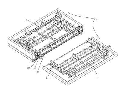
With reference to FIG 1, a detachable bed base 1 according to a preferred
embodiment of the present invention comprises: a first connection assembly
and a second connection assembly 11 which mate with an electric cylinder
5 (not shown).
Each of the first connection assembly 10 and the second connection
assembly 11 includes multiple support rods 12, and a width of the detachable
bed base 1 is within 180 cm to 190 cm, wherein the first connection assembly
10 includes a plurality of first hollow tubes 101 arranged on a bottom
thereof,
10 and the second connection assembly 11 includes a plurality of second
hollow
tubes 111 arranged on a bottom thereof and connecting with the plurality of
first hollow tubes 101 of the first connection assembly 10. The multiple
support rods 12 insert into and extend out of the plurality of first hollow
tubes
101 of the first connection assembly 10 so as to fit with the plurality of
second
hollow tubes 111 of the second connection assembly 11, and multiple screw
elements 13 lock the multiple support rods 12, the plurality of first hollow
tubes 101, and the plurality of second hollow tubes 111 together (as shown in
FIG 2), hence the first connection assembly 10 and the second connection
assembly 11 are connected together. Each of the multiple screw elements 13 is
a butterfly screw and has two wings 13 extending outwardly from a top of said
CA 02941456 2016-09-12
9
each screw element 13 so as to rotate said each screw element 13 tightly or
loosely.
Referring to FIG 3, multiple reinforcement posts 14 are connected
between the first connection assembly 10 and the second connection assembly
11, wherein multiple first C-shaped slats 102 connect the first connection
assembly 10 and some of the multiple reinforcement posts 14 together, and
multiple second C-shaped slats 112 couple the second connection assembly 11
and the others of the multiple reinforcement posts 14 together (as shown in
FIG 4), wherein each of the multiple first C-shaped slats 102 has a first
accommodation recess defined between two peripheral sides of said each first
C-shaped slat 102 so as to accommodate a first end of each of the multiple
reinforcement posts 14, and each of the multiple second C-shaped slats 112
has a second accommodation recess defined between two peripheral sides of
said each second C-shaped slat 112 so as to accommodate a second end of
said each reinforcement post 14. As illustrated in FIG 5, said each first
C-shaped slat 102 has two opposite first through holes 1021 formed on the
two peripheral sides thereof so as to accommodate each of multiple fixing
bolts 15, and a part of said each fixing bolt 15 extends out of one of the two
first through holes 1021 and has an aperture configured to house each of
multiple pins 15, and said each second C-shaped slat 112 has two opposite
CA 02941456 2016-09-12
second through holes 1121 formed on the two peripheral sides thereof so as to
accommodate said each fixing bolt 15, and the part of said each fixing bolt 15
extends out of one of the two second through holes 1121 and has the aperture
configured to insert said each pin 15 (as shown in FIG 6), hence the multiple
5 reinforcement posts 14 support the detachable bed base 1 securely.
With reference to FIG 7, two frames 17 hold the first connection
assembly 10 and the second connection assembly 11, respectively, and each of
the two frames 17 includes a first extension 171 mounted on an outer end of
the first connection assembly 10 or the second connection assembly 11, said
10 each frame 17 also includes two second extensions 172 coupling with two
peripheral sides of the first connection assembly 10 or the second connection
assembly 11, wherein the first extension 171 of said each frame 17 has two
hooks 1712 arranged on two edges thereof and locking with the two second
extensions 172, respectively, wherein each of the two second extensions 172
has a coupling holder 1721 corresponding to a first column 103 of the first
connection assembly 10 or a second column 113 of the second connection
assembly 11, and said each second extension 172 has a fitting trench 1722 and
a positioning member 1723 which are connected with the first connection
assembly 10 or the second connection assembly 11.
In assembly, said first extension 171 is fixed on the outer end of the first
CA 02941456 2016-09-12
I I
connection assembly 10 or the second connection assembly 11, and the
coupling holder 1721 of said each second extension 172 is aligned with the
first column 103 of the first connection assembly 10 or the second column 113
of the second connection assembly 11, then the fitting trench 1722 is fitted
.. with an inverted T-shaped sheet 1031 of the first column 103 of the first
connection assembly 10 (as illustrated in FIG 8), hence said each second
extension 172 is fixed on each of the two peripheral sides of the first
connection assembly 10 or the second connection assembly 11. Thereafter,
each of the two hooks 1712 of the first extension 171 is fitted with the
positioning member 1723 of said each second extension 172 so that the first
extension 171 is coupled with said each second extension 172. Referring
further to FIG 9, a plurality of supporters 181 lock the first column 103, the
second column 113, and the coupling holder 1721 of said each second
extension 172 together, wherein each of the multiple supporters 18 has a
screwing peg 181 extending outwardly from a bottom of said each supporter
18 so as to screw with said each second extension 172, the first column 103 of
the first connection assembly 10, and the second column 113 of the second
connection assembly 11 via the coupling holder 1721 of said each second
extension 172, thus connecting the detachable bed base 1, as shown in FIG 10.
Accordingly, the multiple supporters 18 support the first connection
CA 02941456 2016-09-12
12
assembly 10 and the second connection assembly 11 stably, and the two
frames 17 fix the detachable bed base 1 firmly.
Preferably, the multiple reinforcement posts 14 are connected between the
first connection assembly 10 and the second connection assembly 11 so as to
reinforce the detachable bed base 1. In addition, a driving motor set (not
shown) is housed in the detachable bed base 1 so as to drive a movement of
the detachable bed base 1 easily.
While the prefened embodiments of the invention have been set forth for
the purpose of disclosure, modifications of the disclosed embodiments of the
invention as well as other embodiments thereof may occur to those skilled in
the art. The scope of the claims should not be limited by the preferred
embodiments set forth in the examples, but should be given the broadest
interpretation consistent with the description as a whole.