Note: Descriptions are shown in the official language in which they were submitted.
CA 02941673 2016-09-06
WO 2015/147647 PCT/NL2015/050201
1
Method for lowering a subsea structure haying a substantially flat support
base into the
water through the splash zone
The present invention relates to a method for lowering a subsea structure
having a
substantially flat support base into the water through the splash zone.
In offshore activities subsea equipment is installed on the seabed. For
installing the subsea
equipment on the seabed, the subsea equipment is first transported on a ship
or transport barge to
the location where the subsea equipment is to be installed. Subsequently the
subsea equipment is
lifted from the deck of the ship or transport barge and lowered into the water
through the water
line, the so called splash zone, towards the seabed. Once arrived at the
seabed the subsea
equipment is positioned on the seabed and installed. For preventing the subsea
equipment to sink
into the seabed, the subsea equipment is generally mounted on a relatively
large flat support base,
which generally includes one or more so-called mudmats. Also during transport
of the subsea
equipment, the subsea equipment is generally supported stable on the deck of
the ship or transport
barge on the flat support base.
The present invention has as one of its objects to improve the lowering of a
subsea
structure to be installed on the seabed into the water through the splash
zone, wherein said subsea
structure comprises subsea equipment arranged on a substantially flat support
base for preventing
the subsea equipment to sink into the seabed.
Thereto, the present invention provides a method for lowering a subsea
structure having a
substantially flat support base, in particular a flat support base frame or
flat support base element,
into the water through the splash zone, comprising:
- lifting the subsea structure into the air in a horizontal position in
which the flat support
base extends substantially parallel to the horizontal plane;
- tilting the subsea structure while suspended in the air from the horizontal
position into a
tilted position in which the flat support base is angled with respect to the
horizontal plane;
- lowering the subsea structure into the water through the splash zone in
the tilted position;
and
- tilting the subsea structure while suspended in the water below the
splash zone back into
the horizontal position.
By the first step of lifting the subsea structure into the air in a horizontal
position in which
the flat support base extends substantially parallel to the horizontal plane,
the lifting of the subsea
structure of the deck of a ship or transport barge on which the subsea
structure was supported
during transport is uncomplicated. The latter in particular in view of the
fact that the subsea
structure is for stable support during transport positioned with its flat
support base on the deck and
is consequently already in its horizontal position. Once in the air there is
sufficient free space for
CA 02941673 2016-09-06
WO 2015/147647 PCT/NL2015/050201
2
safely tilting the subsea structure in the air from the horizontal position
into a tilted position in
which the flat support base is angled with respect to the horizontal plane.
The subsequent step of
lowering the subsea structure into the water through the splash zone in the
tilted position is
advantageous in view of the loads on the subsea structure and the hoisting
equipment during the
lowering of the subsea structure through the splash zone. The overall load
applied on the hoisting
equipment and the subsea structure suspended therefrom change dramatically
when the subsea
structure starts touching water, up to the point where it is completely
submerged. In particular
contact with the waves creates widely fluctuating dynamic forces on the subsea
structure and on
the hoisting equipment. If the subsea structure would be lowered into the
splash zone in the
horizontal position thereof, the full area of the flat support base of the
subsea structure would come
into contact with the water at the moment the support base comes into contact
with the water,
resulting in relatively large change in loads applied on the hoisting
equipment and the subsea
structure suspended therefrom. This change of loads can severely damage the
subsea structure and
the hoisting equipment. By lowering according to the invention the subsea
structure into the water
through the splash zone in the tilted position, the full area of the flat
support base of the subsea
structure no longer comes into contact with the water at the moment the
support base comes into
contact with the water. The latter has the advantage that the change in loads
applied on the hoisting
equipment and the subsea structure suspended therefrom resulting from lowering
the subsea
structure through the splash zone is reduced. Once the subsea structure is
fully submerged, and
thus has passed the splash zone, there is sufficient free space to safely tilt
the subsea structure back
to its horizontal position, in which position the flat support base will be
positioned and installed on
the seabed.
The above described sequence of step of the method according to the invention
provides
for uncompleted movements of the subsea structure at the deck of ship or
transport barge and at the
seabed where free space is limited, while the more complicated movement of the
tilting of the
subsea structure is performed in the air and in the water where free space is
available in abundance,
such that damage to the subsea structure and surrounding equipment and people
is prevented.
The method according to the invention thus prevents damage to the subsea
structure and
hoisting equipment as a result of the change in loads on the subsea structure
and the hoisting
equipment by lowering the subsea structure through the splash zone in tilted
position, while also
preventing damage to the subsea structure and surrounding equipment that might
occur as a result
of tilting the subsea structure before and after lowering the subsea structure
trough the splash zone.
The prevention of damage to the subsea structure, to the hoisting equipment,
and to surrounding
equipment allows for extension of the limits for wave height, wind speeds etc.
within which the
lifting of the subsea structure of the ship or transport barge, the tilting of
the subsea structure, and
the lowering of the subsea structure through the splash zone can safely be
performed. For the
CA 02941673 2016-09-06
WO 2015/147647 PCT/NL2015/050201
3
operation of installing subsea equipment on the seabed this makes it possible
to operate within
larger weather windows and thus avoid delay as a result of worsened weather
conditions.
In an advantageous embodiment of the method according to the invention the
tilting of the
subsea structure in the air is performed above the splash zone. Although
alternatively the tilting of
the subsea structure in the air could be performed above the ship or transport
barge on which the
subsea structure was transported, tilting the subsea structure in the air
above the splash zone has
the advantage of further preventing damage to the ship or transport barge as a
result of the tilting of
the subsea structure.
In an advantageous embodiment of the method according to the invention, for
lifting the
subsea structure, the subsea structure is suspended from a substantially flat
lifting frame extending
substantially parallel to the flat base of the subsea structure, wherein the
lifting frame is suspended
from at least one first hoisting cable and at least one second hoisting cable,
each connected to the
lifting frame such that with the subsea structure in the horizontal position,
the vertical component
of the respective lifting forces exerted by the first hoisting cable and the
second hoisting cable on
the lifting frame are offset from the combined center of mass of the lifting
frame and the subsea
structure on opposite sides of the said combined center of mass, and for
tilting the subsea structure
one of the first hoisting cable and second hoisting cable is drawn in or payed
out.
The thus provided first and second hoisting cables allow for a controlled
tilting of the
lifting frame and the subsea structure suspended therefrom by simply drawing
in or paying out the
second hoisting cable while the lifting frame and the subsea structure are
suspended in the air or in
the water. By suspending the subsea structure from a lifting frame extending
parallel to the support
base of the subsea structure while suspending the lifting from the first and
second hoisting cables, a
free space between the arrangement of first and second hoisting cables and the
subsea structure is
provided in which the equipment of the subsea structure that is arranged on
the support base can
freely move when tilting the subsea structure. Preferably, in the tilted
position, the lifting frame is
suspended from the first hoisting cable and the second hoisting cable, wherein
the vertical
component of the respective lifting forces exerted by the first hoisting cable
and the second
hoisting cable on the lifting frame are offset from the combined center of
mass of the lifting frame
and the subsea structure on opposite sides of the said combined center of
mass. This ensures that
the subsea structure can be tilted back into the horizontal position by
drawing in or paying out one
of the first hoisting cable and second hoisting cable.
In an alternative embodiment, for lifting the subsea structure, the subsea
structure is
suspended from a first hoisting cable and a second hoisting cable, each
connected to the subsea
structure such that with the subsea structure in the horizontal position, the
vertical component of
the respective lifting forces exerted by the first hoisting cable and the
second hoisting cable on the
lifting frame are offset from the center of mass of the subsea structure on
opposite sides of the said
CA 02941673 2016-09-06
WO 2015/147647 PCT/NL2015/050201
4
center of mass, and for tilting the subsea structure one of the first hoisting
cable and second
hoisting cable is drawn in or payed out. This alternative embodiment, wherein
the lifting frame is
omitted and the first and second hoisting cables are directly connected to the
subsea structure, is in
particular advantageous in case the shape and size of the equipment of the
subsea structure
arranged on the support base does not interfere with the hoisting cable
arrangement when tilting
the subsea structure. Preferably, in the tilted position, the lifting frame is
suspended from the first
hoisting cable and the second hoisting cable, wherein the vertical component
of the respective
lifting forces exerted by the first hoisting cable and the second hoisting
cable on the lifting frame
are offset from the combined center of mass of the lifting frame and the
subsea structure on
opposite sides of the said combined center of mass. This ensures that the
subsea structure can be
tilted back into the horizontal position by drawing in or paying out one of
the first hoisting cable
and second hoisting cable.
In an advantageous embodiment of the method according to the invention as
described
herein above with first and second hoisting cables, with the subsea structure
in the horizontal
position, the vertical component of the lifting force exerted by the first
hoisting cable is offset from
said center of mass by a first distance, and the vertical component of the
lifting force exerted by the
second hoisting cable is offset from said center of mass by a second distance,
wherein the first
distance is smaller than the second distance.
In this embodiment the first hoisting cable supports more weight than the
second hosting
cable. By applying the features of this embodiment the force that is required
to be applied on the
second hoisting cable for paying out or drawing in the second hoisting cable
for tilting the subsea
structure can thus be lower, such that the force for tilting the subsea
structure can be lower.
In a further advantageous embodiment of the method according to the invention,
the
second hoisting cable is drawn in for tilting the subsea structure from its
horizontal position into its
tilted position and is payed out for tilting the subsea structure from its
tilted position back into its
horizontal position.
In a further advantageous embodiment of the method according to the invention
with first
and a second hoisting cables:
- the first hoisting cable is suspended from a hoisting block;
- the second hoisting cable is led through the hoisting block; and
- a stop is arranged on the second hoisting cable on the side of the pulley
away from the
lifting frame;
wherein in the horizontal position of the subsea structure, the stop is in
contact with the
hoisting block.
By applying the features of this embodiment, gravity pulls the stop against
the hoisting
block when the subsea structure is in its horizontal position. Consequently,
the horizontal position
CA 02941673 2016-09-06
WO 2015/147647 PCT/NL2015/050201
of the subsea structure is maintained when no lifting force is applied to the
second hoisting cable at
the side of the stop away from the hoisting block. This has the advantage that
during the lifting of
the subsea structure from the deck of the ship or transport barge in its
horizontal position and
during the lowering of the subsea structure towards the seabed in its
horizontal position the lifting
5 and lowering can be performed by drawing in and paying out a single main
hoisting cable from
which the hoisting block is suspended. The second hoisting cable can remain
slack on the side of
the stop away from the subsea structure, and no precise coordination of the
winch operating the
main hoisting cable and the winch operating the second hoisting cable is
required for maintaining
the horizontal position of the subsea structure.
The present invention further relates to a system for lowering a subsea
structure having a
substantially flat base into the water through the splash zone, comprising
- lifting means for lifting the subsea structure into the air and for
lowering the subsea
structure into the water through the splash zone;
- tilting means for tilting the subsea structure from a horizontal position
in which the flat
support base extends substantially parallel to the horizontal plane into a
tilted position in which the
flat support base is angled with respect to the horizontal plane;
wherein the lifting means and the tilting means are configured for:
- lifting the subsea structure into the air in the horizontal position;
- tilting the subsea structure while suspended in the air from the
horizontal position into
the;
- lowering the subsea structure into the water through the splash zone in
the tilted position;
and
- tilting the subsea structure while suspended in the water below the
splash zone back into
the horizontal position.
With this system according to the invention, the embodiment of the method
according to
the invention as described herein above in which a lifting frame is used, can
be performed with the
advantage as described herein above with respect to said embodiment.
The present invention further relates to a system for lowering a subsea
structure having a
substantially flat base into the water through the splash zone, comprising:
- a hoisting installation;
- a substantially flat lifting frame suspended from the hoisting
installation and configured
for suspending therefrom the subsea structure;
wherein
- the lifting frame is suspended from the hoisting installation via a first
hoisting cable and a
second hoisting cable, each connected to the lifting frame such that with the
lifting frame in a
horizontal position in which the lifting frame extends substantially parallel
to the horizontal plane,
CA 02941673 2016-09-06
WO 2015/147647 PCT/NL2015/050201
6
the vertical component of the respective lifting forces exerted by the first
hoisting cable and the
second hoisting cable on the lifting frame are offset from the center of mass
of the lifting frame on
opposite sides of said center of mass;
- the hoisting installation comprises a first winch for operating the first
hoisting cable and a
second winch for operating the second hoisting cable independently from the
first hoisting cable.
With this system according to the invention, the embodiment of the method
according to
the invention as described herein above in which a lifting frame is used, can
be performed with the
advantage as described herein above with respect to said embodiment.
In an advantageous embodiment of the system according to the invention the
first hoisting
cable is offset from the center of mass of the lifting frame by a first
distance, and the second
hoisting cable is offset from the center of mass of the lifting frame by a
second distance, wherein
the first distance is smaller than the second distance.
With this embodiment of the system according to the invention, the embodiment
of the
method according to the invention as described herein above in which the first
hoisting cable has a
smaller offset distance and the second hoisting cable, can be performed with
the advantage as
described herein above with respect to said embodiment.
In a further advantageous embodiment of the system according to the invention,
the first
hoisting cable is suspended from a hoisting block, the second hoisting cable
is led through the
hoisting block, and a stop is arranged on the second hoisting cable on the
side of the hoisting block
away from the lifting frame, wherein in the horizontal position of the lifting
frame, the stop is in
contact with the hoisting block.
With this embodiment of the system according to the invention, the embodiment
of the
method according to the invention as described herein above in which the first
hoisting cable has a
smaller offset distance and the second hoisting cable, can be performed with
the advantage as
described herein above with respect to said embodiment.
In a further embodiment of the system according to the invention the hoisting
installation
is arranged on a ship or offshore platform.
The present invention further relates to a set, comprising a subsea structure
having a
substantially flat support base, and a substantially flat lifting frame,
wherein:
- the subsea structure is coupled to the lifting frame for suspension wherein
the
substantially flat support base extends parallel to the substantially flat
lifting frame;
- a first hoisting cable and a second hoisting cable are connected to the
lifting frame for
lifting the lifting frame and the subsea structure suspended therefrom;
wherein
- the first hoisting cable and the second hoisting cable are connected to the
lifting frame
such that with the subsea structure in the horizontal position in which the
substantially flat support
CA 02941673 2016-09-06
WO 2015/147647 PCT/NL2015/050201
7
base extends parallel to the horizontal plane , the vertical component of the
respective lifting forces
exerted by the first hoisting cable and the second hoisting cable on the
lifting frame are offset from
the combined center of mass of the lifting frame and the subsea structure on
opposite sides of the
said combined center of mass; and
wherein
- the second hoisting cable is independently operable from the first
hoisting cable.
The present invention further relates to an assembly for lowering a subsea
structure having
a substantially flat support base into the water through the splash zone,
comprising:
- a substantially flat lifting frame which is configured for suspending
therefrom the subsea
structure;
- a first hoisting cable and a second hoisting cable for lifting the
lifting frame, each
connected to the lifting frame such that with the lifting frame in a
horizontal position in which the
lifting frame extends substantially parallel to the horizontal plane, the
vertical component of the
respective lifting forces exerted by the first hoisting cable and the second
hoisting cable on the
lifting frame are offset from the center of mass of the lifting frame on
opposite sides of said center
of mass, wherein the second hoisting cable is independently operable from the
first hoisting cable.
The present invention is further elucidated in the following description with
reference to
the accompanying schematic figures, in which:
Figures 1 to 4 show in side view an embodiment of a system according to the
invention in
four subsequent moments in time during the performance of an embodiment of the
method
according to the invention.
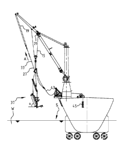
In figures 1 to 4 a hoisting installation 1 is shown which is arranged on a
ship 3 of which
the hull 5 is shown and thrusters 7. The hoisting installation 1 has a crane 9
with a boom 11 and a
jib 13. The hoisting installation 1 is provided with a main hoisting cable 15
operated by means of a
main winch 17 and an auxiliary hoisting cable 19 operated by means of an
auxiliary winch 21.
Suspended from the hoisting installation 1 is a substantially flat lifting
frame 23. The
lifting frame 23 is suspended from the hoisting installation 1 via a first
hoisting cable 25 and a
second hoisting cable 27. The first hoisting cable 25 is connected at one end
to the lifting frame 23
and at an opposite end to a hoisting block 29 that, in turn, is connected to
the main hoisting cable
15. The lifting frame 23 extends in a plane perpendicular to the drawing plane
of figure 1. In order
to prevent the tilting of the lifting frame 23 about the line 1 where the
horizontal plane in which the
lifting frame extends intersects the plane of the drawing, the first hoisting
cable 25 is split into two
cables 25a, 25b. This is shown in figure 1A in which the lifting frame 23 is
shown in side view in a
vertical plane perpendicular to the drawing plane of figure 1. The second
hoisting cable 27 is at one
end to the lifting frame 23 and led through the hoisting block 29 over a
pulley 31 provided in the
CA 02941673 2016-09-06
WO 2015/147647
PCT/NL2015/050201
8
hoisting block 29. A stop 33 is arranged on the second hoisting cable 15 on
the side of the hoisting
block 29 away from the lifting frame 23.
Suspended from the lifting frame 23 by means of cables 35 is a subsea
structure 37 that is
to be installed on the seabed. The subsea structure 37 has a substantially
flat support base 39 and
subsea equipment 41 arranged thereon. The cables 35 are arranged such that the
flat support base
39 of the subsea structure 37 is suspended parallel to the lifting frame 23.
In particular the lifting
frame 23, the support base 39 and the cables 35 are arranged in a
parallelogram configuration. For
connecting the cables 35 the subsea structure 37 and the lifting frame 23 are
provided with pad
eyes at corners of the lifting frame and the support base.
In figure 1 the subsea structure 37 is suspended in its horizontal position in
which the flat
support base 39 extends substantially parallel to the horizontal plane. The
horizontal plane extends
perpendicular to the plane of the drawing. The first hoisting cable 25 is
connected to the lifting
frame 23 such that with the subsea structure 37 in the shown horizontal
position, the vertical
component Fv1 of the lifting force exerted by the first hoisting cable 25 is
offset from the combined
center of mass M of the lifting frame 23 and the subsea structure 37 by a
first offset distance d1.
The second hoisting cable 27 is connected to the lifting frame 23 such that
with the subsea
structure 37 in the shown horizontal position, the vertical component Fv2 of
the lifting force exerted
by the second hoisting cable 27 is offset from the combined center of mass M
of the lifting frame
23 and the subsea structure 37 by a second offset distance d2. The first
offset distance d1 is smaller
than the second offset distance d2. As a result of gravity, the stop 33 is
pulled against the hoisting
block 29. The auxiliary hoisting cable 19 is slack, such that all weight is
supported by the main
hoisting cable 17.
In figure 1 the subsea structure 37 has been lifted of the deck 41 of the ship
3, where it was
positioned on its support base 37 in its horizontal position during its
transport to the location where
it is to be installed, and has been lifted in the air above the splash zone S.
In figure 2 is shown that, from the situation shown in figure 2, by drawing in
the second
hoisting cable 27 by pulling the second hoisting cable 27 in direction of
arrow A by means of
auxiliary hoisting cable 19 and auxiliary winch 21, the subsea structure 37
has been tilted while
suspended in the air from the horizontal position (shown in figure 1) into a
tilted position (shown
in figure 2) in which the flat support base 39 is angled a with respect to the
horizontal plane.
During the tilting of the subsea structure 37, the main hoisting cable 15 has
remained stationary.
In figure 3 is shown that from the situation shown in figure 2 the subsea
structure 37 has
been lowered into the water W through the splash zone S in the tilted position
by paying out both
main hoisting cable 17 and auxiliary hoisting cable 19 in the direction of
arrows B. As shown in
figure 3 the subsea structure 37 has been lowered in its tilted position into
a location in the water
below the splash zone S.
CA 02941673 2016-09-06
WO 2015/147647 PCT/NL2015/050201
9
In figure 4 is shown that, from the situation shown in figure 3, by paying out
the second
hoisting cable 27, in particular by paying out auxiliary hoisting cable 19 in
the direction of arrow C
while remaining the main hoisting cable 15 stationary, the subsea structure 37
has been tilted while
suspended in the water W below the splash zone S back from its tilted position
(shown in figure 3)
back into its horizontal position (shown in figure 4). In figure 4 the
auxiliary hoisting cable 19 is
slack, such that the subsea structure 37 is fully supported by the main
hoisting cable 15.
From the situation shown in figure 4 the subsea structure 37 is further
lowered towards the
seabed in the direction of arrow D by paying out the main hoisting cable 15
and the auxiliary
hoisting cable 19 by means of main winch 17 and auxiliary winch 21. Since the
distance to the
seabed can be large, for instance more than 1000 meters, a long range hoisting
cable 43 coupled to
the hoisting block 29 and a long range winch 45 are provided that take over
the lowering of the
subsea structure 37 and lifting frame 23 towards the seabed after decoupling
of the main hoisting
cable 15 from the hoisting block 29 and decoupling of the auxiliary hoisting
cable 19 from the
second hoisting cable 25. As a result of gravity the stop 33 is pulled against
the hoisting block 29,
such that the subsea structure 37 remains in its horizontal position even
though no hoisting cable is
connected to the end of the second hoisting cable 25 away from the lifting
frame 23. In more
shallow water, the main hoisting cable 15 can be used to lower the subsea
structure 37 all the way
to the seabed.
The subsea structure 37 is lowered to the seabed in its horizontal position,
where it is
installed on the seabed.
While the principles of the invention have been set out above in connection
with specific
embodiments, it is to be understood that this description is merely made by
way of example and
not as a limitation of the scope of protection, which is determined by the
appended claims.