Note: Descriptions are shown in the official language in which they were submitted.
DIAPHRAGM ACTUATORS HAVING ADJUSTABLE ACTUATION FORCE
FIELD OF THE DISCLOSURE
[0001] This patent relates generally to actuators and, more
particularly, to diaphragm
actuators having adjustable actuation force.
BACKGROUND
[0002] Fluid control valves are commonly distributed throughout process
control
systems to control flow rates and/or pressures of various fluids (e.g.
liquids, gases, etc.). A
fluid control valve assembly typically includes a valve body, a stem, and an
actuator (e.g., a
pneumatic actuator) to displace the valve stem to operate the fluid control
valve. Typically,
movement of an actuator stem moves the valve stem to position a plug or flow
control
member within the valve. In the case of a diaphragm actuator, an input
pressure (e.g.,
pressurized gas, fluid, etc.) is applied to a chamber of the actuator to
displace the diaphragm.
The input pressure necessary to displace the diaphragm is typically defined by
multiple
parameters including diaphragm and spring selection, tolerances of components,
assembly
variation, etc. Typically, the flow controlled by the actuator is largely
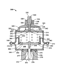
defined by component
selection and tolerances, thereby resulting in significant variability in
actuation response
(e.g., input pressure necessary to actuate the diaphragm actuator).
Additionally, the operating
flow controlled by the fluid control valve may necessitate adjustments to the
actuator over
the operating life of the actuator as the flow through the fluid control valve
may change (e.g.,
drift) over time.
SUMMARY
[0003] According to one aspect of the present disclosure, an object is to
provide an apparatus
for use as a diaphragm actuator having an adjustable actuation force, the
apparatus
comprising:
a spring seat coupled to a diaphragm of an actuator, the spring seat to
contact a spring
and to be coupled to a stem, the diaphragm to displace the stem based on a
force provided to
the diaphragm, the stem to control a fluid valve, the spring seat having
adjacent first and
second annular recesses with different diameters to define a first stepped
profile, wherein the
spring seat has a first thickness, and wherein the first and second annular
recesses have
1
Date Recue/Date Received 2022-03-01
second and third thicknesses, respectively, the first thickness encompassing
the second and
third thicknesses; and
an adjuster to adjust an amount of force provided to the spring seat by the
spring, the
adjuster having adjacent third and fourth annular recesses with different
diameters to define a
second stepped profile to engage the first stepped profile, the adjuster
including a second
spring seat to contact the spring on an end of the spring opposite the spring
seat, the spring
seat having an edge to limit a range of motion of the spring seat relative to
the second spring
seat.
[0003a] According to another aspect of the present disclosure, an object is to
provide an
apparatus for use as a diaphragm actuator having an adjustable actuation
force, the apparatus
comprising:
a spring seat coupled to a diaphragm of an actuator, the spring seat to
contact a spring
and to be coupled to a stem, the diaphragm to displace the stem based on a
force provided to
the diaphragm, the stem to control a fluid valve, the spring seat having
adjacent first and
second annular recesses with different diameters to define a first stepped
profile, wherein the
spring seat has a first thickness, and wherein the first and second annular
recesses have
second and third thicknesses, respectively, the first thickness encompassing
the second and
third thicknesses; and
an adjuster that is operated from outside the actuator, the adjuster to adjust
an amount
of force provided to the spring seat by the spring, the adjuster having
adjacent third and
fourth annular recesses with different diameters to define a second stepped
profile to engage
the first stepped profile.
[0003b] According to another aspect of present disclosure, an object is to
provide an
apparatus for use as a diaphragm actuator having an adjustable actuation
force, the apparatus
comprising:
a diaphragm of a valve actuator, the diaphragm to displace a stem based on a
force
provided to the diaphragm, the stem to control a fluid valve;
a first spring seat coupled to the diaphragm;
la
Date Recue/Date Received 2022-03-01
an adjuster in contact with a second spring seat, the second spring seat
having
adjacent first and second annular recesses with different diameters to define
a first stepped
profile, the adjuster having adjacent third and fourth annular recesses with
different diameters
to define a second stepped profile to engage the first stepped profile,
wherein the second
spring seat has a first thickness, and wherein the first and second annular
recesses have
second and third thicknesses, respectively, the first thickness encompassing
the second and
third thicknesses;
a housing having a threaded aperture to receive a threaded portion of the
adjuster,
wherein the adjuster displaces the second spring seat to adjust an amount of
force provided to
the diaphragm by a spring; and
a seal disposed within a seal gland to seal the housing to the adjuster.
[0003c1 According to another aspect of the present disclosure, an object is to
provide an
apparatus for use as a diaphragm actuator having an adjustable actuation
force, the apparatus
comprising:
a valve stem of a fluid actuator to be displaced by a diaphragm based on a
force
provided to the diaphragm, the diaphragm coupled to a first spring seat;
a second spring seat in contact with an adjuster, the adjuster to have a
central aperture
to receive the valve stem, the second spring seat having adjacent first and
second annular
recesses with different diameters to define a first stepped profile, the
adjuster having adjacent
third and fourth annular recesses with different diameters to define a second
stepped profile
to engage the first stepped profile, wherein the second spring seat comprises
an edge to limit
a range of motion of the second spring seat relative to the first spring seat,
wherein the edge
is to contact an adjustable travel stop, and wherein the adjustable travel
stop is to be adjusted
to vary the range of motion of the second spring seat relative to the first
spring seat; and
a housing having a threaded central aperture to receive a threaded portion of
the
adjuster, wherein the adjuster displaces the second spring seat to adjust an
amount of force
provided to the diaphragm by a spring.
lb
Date Recue/Date Received 2022-03-01
[0003d] According to another aspect of the present disclosure, an object is to
provide an
apparatus for use as a diaphragm actuator having an adjustable actuation
force, the apparatus
comprising:
a spring seat coupled to a first diaphragm of an actuator, the spring seat to
contact a
.. spring and to be coupled to a stem, the first diaphragm to displace the
stem based on a force
provided to the first diaphragm, the stem to control a fluid valve, the spring
seat having
adjacent first and second annular recesses with different diameters to define
a first stepped
profile;
a second diaphragm coupled to the spring seat; and
an adjuster to adjust an amount of force provided to the spring seat by the
spring, the
adjuster having adjacent third and fourth annular recesses with different
diameters to define a
second stepped profile to engage the first stepped profile.
[0003e] Other possible aspect(s), object(s), embodiment(s), variant(s) and/or
advantage(s) of
the present disclosure, all being preferred and/or optional, are briefly
summarized
hereinbelow.
[00031] For example, one described example apparatus includes a spring seat
coupled to a
diaphragm of an actuator. The spring seat is to contact a spring and coupled
to a stem. The
diaphragm displaces the stem based on a force provided to the diaphragm and
the stem is to
control a fluid valve. The example apparatus also includes an adjuster to
adjust an amount of
force provided to the spring seat by the spring.
[0004] Another described example apparatus includes a diaphragm of a valve
actuator. The
diaphragm displaces a stem based on a force provided to the diaphragm and the
stem controls
a fluid valve. The example apparatus also includes a first spring seat coupled
to the
diaphragm and an adjuster in contact with a second spring seat opposite the
first spring seat.
The example apparatus also includes a spring to contact the first spring seat
and the second
spring seat at opposing ends and a housing having a threaded aperture to
receive a threaded
portion of the adjuster. The adjuster displaces the second spring seat.
1C
Date Recue/Date Received 2022-03-01
CA 02941692 2016-09-02
WO 2015/142809 PCT[US2015/020910
[0005] Another described example apparatus includes a valve stem of a fluid
actuator to
be displaced by a diaphragm based on a force provided to the diaphragm. The
diaphragm is
coupled to a first spring seat. The first spring seat coupled is to the
diaphragm. The example
apparatus also includes a second spring seat in contact with an adjuster. The
adjuster has a
central aperture to receive the valve stem. The example apparatus also
includes a spring to
contact the first spring seat and the second spring seat at opposing ends and
a housing having
a threaded central aperture to receive a threaded portion of the adjuster.
BRIEF DESCRIPTION OF THE DRAWINGS
[0006] FIG. lA is a cross-sectional view of a known reverse-acting
diaphragm actuator.
[0007] FIG. 1B is a cross-sectional view of another known reverse-acting
diaphragm
actuator, which has an adjustable spring.
[0008] FIG. 2 is a cross-sectional view of a known direct-acting diaphragm
actuator.
[0009] FIG. 3 is a cross-sectional view of an example reverse-acting
diaphragm actuator
in accordance with the teachings of this disclosure.
[0010] FIG. 4 is a cross-sectional view of an example direct-acting
diaphragm actuator.
[0011] FIG. 5 is a cross-sectional view of another example double-acting
diaphragm
spring-to-extend actuator.
[0012] FIG. 6 is a cross-sectional view of another example double-acting
diaphragm
spring-to-retract actuator.
[0013] FIG. 7 is a cross-sectional view of another example reverse-acting
diaphragm
actuator that has adjustable stops to limit travel of a spring seat.
[0014] The figures are not to scale. Instead, to clarify multiple layers
and regions, the
thickness of the layers may be enlarged in the drawings. Wherever possible,
the same
reference numbers will be used throughout the drawing(s) and accompanying
written
description to refer to the same or like parts. As used in this patent,
stating that any part (e.g.,
a layer, film, area, or plate) is in any way positioned on (e.g., positioned
on, located on,
disposed on, or formed on, etc.) another part, means that the referenced part
is either in
contact with the other part, or that the referenced part is above the other
part with one or more
intermediate part(s) located therebetween. Stating that any part is in contact
with another part
means that there is no intermediate part between the two parts.
DETAILED DESCRIPTION
[0015] Many known diaphragm actuators employ a diaphragm to receive an
input force
to displace a valve stem, which controls a fluid valve, thereby altering the
fluid flow
- 2 -
CA 02941692 2016-09-02
WO 2015/142809 PCT/US2015/020910
characteristics through the fluid valve. In direct-acting diaphragm actuators,
applying an
input control pressure from a fluid (e.g., gas, air, etc.) moves the diaphragm
to extend the
actuator stem. In reverse-acting diaphragm actuators, applying an input
control pressure from
a fluid (e.g., gas, air, etc.) moves the diaphragm up to retract the actuator
stem. Some known
diaphragm actuators include a spring to provide (e.g., maintain) a force to
the diaphragm to
define a desired relationship between the control pressure and actuator stem
displacement.
This relationship may vary due to factors including spring(s) and/or
diaphragm(s) selection,
tolerances of the components, variation in manufacturing, etc. The
characteristics of the
diaphragm actuator may also change with time (e.g., drift, etc.) as the
diaphragm actuator is
used. Additionally, known diaphragm actuators may expose service/maintenance
personnel to
a fully or partially loaded spring when the diaphragm actuator is disassembled
due to these
known systems lacking mechanisms or features to decrease spring load prior the
actuator
being opened for service and/or maintenance. Some known actuators may allow
adjustability
via an externally exposed spring. Such exposure to external conditions may be
disadvantageous in harsh environmental conditions (e.g., high temperature,
highly corrosive,
etc.).
[0016] The example diaphragm actuators disclosed herein enable adjustment
of
diaphragm actuation forces with an internally positioned adjustment spring.
More
specifically, the example apparatus described herein eliminate the need for
force adjustments
through diaphragm and/or spring replacements, thereby allowing adjustment of
the actuation
force in the field and/or in a manufacturing setting without exposing the
adjustment spring to
external conditions, for example. Additionally, the examples disclosed also
enable field
adjustment to compensate for performance shift (e.g., performance drift,
performance
variation, etc.) of the example diaphragm actuators. As a result, the examples
disclosed
herein eliminate the need to stock and/or inventory numerous different springs
and/or
diaphragms to accommodate different applications, thereby potentially
improving profit
margins and/or supply chain flexibility. The examples described herein may
improve
reliability and/or useful life of the adjustment spring by internally
positioning the adjustment
spring. Reducing the number of unique components by combining multiple
configurations
into a single Stock Keeping Unit (SKU) reduces inventory complexity and
simplifies part
number management and Bill of Materials (BOM) tracking. Reductions in SKUs
also allows
reduction of spare part inventories and complex supply chain management of
numerous
configurations. Additionally, the examples disclosed herein allow spring load
force applied to
- 3 -
CA 02941692 2016-09-02
WO 2015/142809 PCT/US2015/020910
a diaphragm to be reduced prior to disassembly of the diaphragm actuator to
reduce potential
exposure of service and/or maintenance staff to a spring under load.
[0017] In some examples, a spring may contact a spring seat, which may be
coupled to a
diaphragm. The spring seat may have an adjuster (e.g., an adjustment knob) to
displace the
spring seat, thereby changing the spring force applied to the diaphragm and,
thus, altering the
amount of force needed to displace the diaphragm. To facilitate access to the
adjuster, the
adjuster may have an access point external to the diaphragm actuator. For
example, the access
point may be a hex socket to interface with a tool, for example.
[0018] In some examples, the diaphragm actuator may have two or more
diaphragms
coupled to a spring seat. Other examples may have adjustable mechanical stops
to limit a
range through which the seat spring and/or the diaphragm displaces.
[0019] Before describing the example diaphragm actuators mentioned above, a
brief
description of known diaphragm actuators is provided below in connection with
FIGS. IA,
1B and 2. Turning to FIG. 1A, a cross-sectional view of a diaphragm actuator
100 is
provided. The actuator 100 is a reverse-acting (e.g., air-to-open) diaphragm
actuator, which
includes an upper casing (e.g., housing) 102 coupled to a lower casing (e.g..
housing) 104
with a plurality of fasteners (e.g., screws, bolts, rivets etc.) 108, 110
spaced along an exterior
edge of the casings 102 and 104 in a conventional manner. A diaphragm 112
separates the
space within the casings 102, 104 into a control pressure chamber 114 and an
atmospheric
pressure chamber 116. The diaphragm 112 is coupled at an end of the diaphragm
112 to a
spring seat 118 and positioned (e.g., captured, retained) by the casings 102,
104. In some
examples, the fasteners 108, 110 may pass through respective apertures of the
diaphragm
112. The spring seat 118 is coupled to an actuator stem 120 via a fastener
122. In the
illustrated example, the actuator stem 120 is to be coupled to a stem of a
fluid control valve.
In particular, displacement of the actuator stem 120 moves the valve stem to
vary a fluid flow
in the fluid control valve by positioning or moving a plug or flow control
member of the fluid
control valve.
[0020] In operation, displacement of the actuator stem 120 occurs in
response to an input
pressure in the control pressure chamber 114. The input pressure displaces the
diaphragm 112
of the illustrated example in an upward direction in the orientation shown in
FIG. 1A. In
particular, the input pressure displaces at least a portion of the diaphragm
112 when the input
pressure applied to the control pressure chamber 114 produces a force on the
diaphragm 112
that exceeds a spring force provided by a spring 124. The upward movement of
the
- 4 -
CA 02941692 2016-09-02
WO 2015/142809 PCT/US2015/020910
diaphragm 112 and, thus, the spring seat 118, in turn, moves the stem 120 and
any valve stem
coupled thereto upward, thereby changing the flow of fluid through a fluid
valve.
[0021] In the illustrated example, the amount of force needed to displace
the diaphragm
112 is affected by spring selection, tolerances, compression distances of the
spring, and/or
elasticity of the diaphragm 112, etc.
[0022] FIG. 1B illustrates a cross-sectional view of another known reverse-
acting
diaphragm actuator 130. The actuator 130 includes an upper casing 132 coupled
to a lower
casing 134 with a plurality of fasteners (e.g., screws, bolts, rivets etc.)
136, 138 spaced along
an exterior edge of the casings 132 and 134 in a conventional manner. A
diaphragm 140
separates the space within the casings 132, 134 into a control pressure
chamber 142 and an
atmospheric pressure chamber 144. The diaphragm 140 is coupled at an end of
the diaphragm
140 to a diaphragm plate 146 and positioned (e.g., captured, retained) by the
casings 132,
134. In some examples, the fasteners 136, 138 may pass through respective
apertures of the
diaphragm 140. The diaphragm plate 146 is coupled to an actuator stem 148 via
a fastener
150. In the illustrated example, the actuator stem 148 is to be coupled to a
valve stem 151 of
a fluid control valve. In particular, displacement of the actuator stem 148
moves the valve
stem 151 to vary a fluid flow in the fluid control valve by positioning or
moving a plug or
flow control member of the fluid control valve. In this example, a force
provided to the
diaphragm plate 146 by a spring 152 may be adjusted via a spring seat 154
(e.g., displacing
the spring seat 154 relative to the lower casing 134). The spring seat 154 may
be displaced
via a spring adjuster 156, which may be rotated to displace the spring seat
154. In the
illustrated example, the spring 152 is externally exposed.
[0023] In operation, displacement of the actuator stem 148 occurs in
response to an input
pressure in the control pressure chamber 142. The input pressure displaces the
diaphragm 140
of the illustrated example in an upward direction in the orientation shown in
FIG. 1B. In
particular, the input pressure displaces at least a portion of the diaphragm
140 when the input
pressure applied to the control pressure chamber 142 produces a force on the
diaphragm 140
that exceeds a force provided by a spring 152. The upward movement of the
diaphragm 140
and, thus, the diaphragm plate 146 moves the stem 148 and the valve stem 151
upward,
thereby changing the flow of fluid through the fluid valve.
[0024] FIG. 2 illustrates a cross-sectional view of another known diaphragm
actuator
200, which is direct-acting (e.g., air-to-close). Similar to the diaphragm
actuators 100, 130
shown above in connection with FIGS. lA and 1B, a peripheral edge of a
diaphragm 202 is
- 5 -
CA 02941692 2016-09-02
WO 2015/142809 PCT/US2015/020910
positioned (e.g., captured) between an upper casing 204 and a lower casing
206. In the
illustrated example, the upper casing 204 is coupled to the lower casing 206
with a plurality
of fasteners (e.g., screws, bolts, rivets etc.) 208, 210 spaced along an
exterior edge of the
casings 204, 206 in a conventional manner and, in some examples, the fasteners
208, 210
may extend through respective apertures of the diaphragm 202 near a peripheral
edge of the
diaphragm 202. The diaphragm 202 is captured between the casings (e.g.,
housings) 204, 206
and separates the space within the casings 204, 206 into a control pressure
chamber 212 and
an atmospheric pressure chamber 214. The diaphragm 202 is coupled to a spring
seat 215 at a
central portion of the diaphragm 202. In the illustrated example, a stem 216
is coupled to the
spring seat 215 and moves with the spring seat 215 to control a fluid valve.
In particular, the
stem 216 is coupled to a stem of the fluid valve to move a plug or fluid
control member of the
fluid valve to vary a fluid flow therethrough.
[0025] In operation, displacement of the actuator stem 216 of the
illustrated example
occurs in response to an input pressure being provided into the control
pressure chamber 212.
The input pressure displaces the diaphragm 202 in a downward direction in the
orientation
shown in FIG. 2. In particular, the input pressure displaces at least a
portion of the diaphragm
202 when the input pressure is applied to the control pressure chamber 212,
thereby
displacing the spring seat 215 downward and, thus, counteracting a spring
force provided by
a spring 218. The downward movement of the spring seat 215, in turn, displaces
the actuator
stem 216 downward. Similar to the actuators 100, 130 the force needed to
displace the
diaphragm 202 is affected by spring selection, tolerances, compression
distances of the
spring, elasticity of the diaphragm 202, etc.
[0026] FIG. 3 is a cross-sectional view of an example actuator 300 in
accordance with
the teachings of this disclosure. The example actuator 300 of FIG. 3 is
reverse-acting (e.g.,
air-to-open). With reference to FIG. 3, a diaphragm 302 is positioned (e.g.,
captured) between
an upper casing 304 and a lower casing 306 with a plurality of fasteners 308,
310.
[0027] A spring 312 of the illustrated example is positioned (e.g.,
captured, encased, etc.)
internally within the actuator 300 and between an upper spring seat 314 and a
lower spring
seat 316. In the illustrated example, the upper spring seat 314, which
contacts (e.g., engages)
a first end of the spring 312, is disposed within a recess 320 of the upper
casing 304. The
recess 320 of the upper casing 304 may be used to align the upper spring seat
314 via a wall
322 that may contact and/or align a peripheral edge 323 of the upper spring
seat 314. An
adjuster 324 of the illustrated example is in contact with the upper spring
seat 314. In the
- 6 -
CA 02941692 2016-09-02
WO 2015/142809 PCT/US2015/020910
illustrated example, the upper casing 304 has a threaded aperture 325 to
threadably engage a
threaded portion 326 of the adjuster 324. The upper casing 304 of the
illustrated example also
has an aperture 328 to receive a portion 329 of the adjuster 324, which has a
recess 330 to
define a gap in which the adjuster 324 may displace relative to the upper
casing 304. Such a
gap may apply to any of the examples disclosed herein. In some examples, the
adjuster 324
may have an aperture 332 to receive a tool. The aperture 332 may be hex shaped
or any other
appropriate shape to receive the tool. In the illustrated example, the
aperture 332 is externally
accessible. In some examples, the tool may alternatively or additionally be
used to engage
and/or contact an external surface (e.g., flats or other feature) of the
adjuster 324. The
aperture 328 of the illustrated example, in some examples, includes a seal
cavity 334 to
receive an 0-ring or gasket, for example, to seal the adjuster 324 to the
upper casing 304.
[0028] The adjuster 324 may have a bearing surface 335 to position and/or
contact a
recess 336 of the upper spring seat 314. The bearing surface 335 of the
illustrated example
allows the upper spring seat 314 to remain relatively stationary (e.g., does
not rotate) as the
adjuster 324 is rotated. While contact with the bearing surface 335 is shown,
any appropriate
type of contact may be used, including but not limited to a bearing interface
(e.g., ball
bearing), a rotating joint, etc. Alternatively, the adjuster 324 may be
coupled to the upper
spring seat 314 via welding, adhering, or any other appropriate manufacturing
process.
[0029] In some examples, the upper casing 304 may engage and/or restrict a
surface of
the upper spring seat 314 such as a surface 338, for example, to further align
and/or constrain
the upper spring seat 314. A gap depicted by an arrow 340 depicts a distance
the upper spring
seat 314 may move in a longitudinal direction relative to the upper casing
304. In some
examples the upper casing 304 may have a contour to matably receive a surface
342 (e.g.,
annular surface, annular bevel, etc.) of the upper spring seat 314.
[0030] The lower spring seat 316 of the illustrated example is coupled to
an actuator
stem 344 via a fastener 348. In the illustrated example, the lower spring seat
316 contacts
(e.g., engages) a second end of the spring 312. In the illustrated example,
the lower spring
seat 316 has a side wall 350 and a plate 358 coupled together to constrain the
spring 312 from
side-to-side or lateral displacement. In some examples, the diaphragm 302 may
have a tab or
lip 362 to be retained by the side wall 350 and/or the plate 358. The lower
spring seat 316 of
the illustrated example sealingly engages the diaphragm 302 at an interface
between the side
wall 350 and the plate 358. The side wall 350 of the illustrated example also
has an edge 364
to contact the upper casing 304, thereby limiting the range of motion or
displacement of the
- 7 -
CA 02941692 2016-09-02
WO 2015/142809 PCT/US2015/020910
lower spring seat 316 relative to the upper casing 304. Additionally or
alternatively, in some
examples, the edge 364 may limit the displacement of the lower spring seat 316
by contacting
upper spring seat 314.
[0031] In some examples, the lower spring seat 316 and/or the upper spring
seat 314 may
have protrusions (e.g., annular or ring-shaped protrusions) 366 to further
constrain the spring
312 (e.g., prevent or reduce side-to-side motion of the spring 312).
Additionally or
alternatively, other biasing elements may be used (e.g., fluid bladders,
etc.). The actuator 300
may have a single spring or multiple springs between the lower spring seat 316
and the upper
seat 314. Multiple springs may be arranged in a concentric pattern or may be
arranged in a
non-concentric pattern. Employing multiple springs may allow increased
compactness of the
actuator 300 (e.g., higher spring force per displacement) and/or greater
redundancy, etc.
[0032] In operation, an input pressure may be provided to a control
pressure chamber
368 to displace the diaphragm 302 and the lower spring seat 316 against the
force of the
spring 312 to move the lower spring seat 316 in an upward direction in the
orientation of FIG.
3. A chamber 370 of the illustrated example may be at atmospheric pressure or
at another
defined pressure to provide a pressure differential relative to the control
pressure chamber
368.
[0033] The upward motion of the lower spring seat 316, in turn, displaces
the stem 344
upward along a central axis defined by a bushing 372 in the lower casing 306.
The bushing
372 of the illustrated example has annular walls 374. 376, which define a
stepped profile or
flange to couple and/or engage a corresponding stepped profile 377 of the
lower casing 306.
In some examples, the lower casing and/or the bushing 372 may have seal
cavities 378 to seal
the control pressure chamber 368 along interfaces defined by the bushing 372
and/or the
lower casing 306 near the actuator stem 344.
[0034] The amount of spring force counteracting the input force applied via
a control
pressure in the lower chamber 368 may be varied by displacing the adjuster 324
and, in turn,
displacing the upper spring seat 314. To adjust the force applied to the
diaphragm 302 by the
spring 312, the adjuster 324 is rotated to displace the adjuster 324 to
displace relative to the
upper casing 304 and, therefore, adjust the amount of force provided to the
lower spring seat
316 and/or the diaphragm 302 by the spring 312.
[0035] In other words, the adjuster 324 allows the amount of force
counteracting the
input force provided to the diaphragm 302 via the control pressure chamber 368
to be
adjusted (e.g., customized or tuned to specific applications and/or adjusted
to precise
- 8 -
CA 02941692 2016-09-02
WO 2015/142809 PCT/US2015/020910
operating specifications, etc.) and may also be used to decrease compression
force of the
spring 312 prior to disassembly of the upper casing 304 from the actuator 300
during
servicing or maintenance operations to, for example, prevent service personnel
from exposure
to a fully or partially loaded spring during servicing of the actuator 300.
The amount of force
applied to the diaphragm 302 via displacement of the upper spring seat 314 may
be adjusted
in the field and/or fine-tuned to satisfy specific applications. As mentioned
above, a gap
depicted by the double arrow 340 indicates the range over which the upper
spring seat 314
may move within the recess 320. In contrast to the known actuators 100. 130,
200, the
example actuator 300 allows adjustment of the spring force applied to the
diaphragm 302 via
adjustment (e.g., alteration) of the compression of the spring 312 while
positioning the spring
312 internally to prevent exposure of the spring 312 to external conditions.
This allows a
wide range of adjustability while eliminating the requirement for tight
tolerances of parts,
fits, etc. and/or components specific to varying applications while
potentially increasing
useful life of the spring 312.
[0036] FIG. 4 is a cross-sectional view of an example direct-acting (e.g.,
air-to-close)
actuator 400. As depicted in FIG. 4, a diaphragm 402 is positioned (e.g.,
captured) between
an upper casing 404 and a lower casing 406 with a plurality of fasteners 408,
410 that, in
some examples, may pass through respective apertures of the diaphragm 402. In
contrast to
the actuator 300 described in connection with FIG. 3, an adjuster 412 is in
contact with a
lower spring seat 414 instead of an upper spring seat 416.
[0037] In the illustrated example, a spring 418 is positioned (e.g.,
captured) internally
within the actuator 400 and between the lower spring seat 414 and the upper
spring seat 416.
In the illustrated example, the lower spring seat 414 contacts (e.g., engages)
a first end of the
spring 418 and is disposed within the lower casing 406. In the illustrated
example, the lower
casing 406 has annular surfaces 424, 426 defining a stepped profile to accept
an insert 428
having a threaded aperture 430 and a corresponding stepped profile to contact
the surfaces
424, 426 of the lower casing 406. In the illustrated example, the threaded
aperture 430 of the
insert 428 engages threads 432 of the adjuster 412, which has a central
aperture 434 to accept
a stem 436. The stem 436 of the illustrated example moves along a central bore
defined by
the central aperture 434. Alternatively, in some examples, the insert 428 is
integral with the
lower casing 406. In examples where a differential pressure is applied to a
chamber 440 (i.e.,
as opposed to the chamber 440 being at atmospheric pressure), a seal 438,
which may be an
0-ring or gasket, substantially prevents leaking from the chamber 440 to an
external
- 9 -
CA 02941692 2016-09-02
WO 2015/142809 PCT/US2015/020910
environment of the actuator 400. Additionally or alternatively, in such
examples, a seal 441,
which may be an 0-ring or a gasket, in some examples, seals the chamber 440.
[0038] The adjuster 412 may have bearing surfaces 442, 444 defining a
stepped profile
to contact a corresponding stepped profile 445 of the lower spring seat 414.
The bearing
surfaces 442, 444 of the illustrated example allow the lower spring seat 414
to remain
relatively stationary (e.g., does not rotate) as the adjuster 412 is rotated.
The adjuster 412 of
the illustrated example also has a protrusion (e.g., wall) 446 to constrain or
prevent lateral
movement of the spring 418.
[0039] While contact via the bearing surfaces 442, 444 is shown, any
appropriate type of
contact between the adjuster 412 and the lower spring seat 414 may be used
including, but
not limited to a bearing interface (e.g., ball bearing), etc. Alternatively,
the adjuster 412 may
be coupled to the lower spring seat 414 by welding, adhering, or any other
appropriate
manufacturing process. Additionally or alternatively, the adjuster 412 may
have an aperture
447 to receive a tool. The aperture 447 may be externally accessible and hex
shaped or any
other appropriate shape to receive the tool. In some examples, the tool may
contact an
external surface (e.g., outer surface) of the adjuster 412.The stem 436 of the
illustrated
example is coupled to the upper spring seat 416 via contact between a surface
448 of the stem
436 and a surface 450 of the upper spring seat 416. In other examples, the
stem 436 may not
be coupled to the upper spring seat 416 and may, instead, only contact the
upper spring seat
416 (e.g., the stem 436 is displaced by bearing surface contact of the upper
spring seat 416 to
the valve stem 436).
[0040] In the illustrated example, the upper spring seat 416 contacts
(e.g., engages) a
second end of the spring 418. In this example, the upper spring seat 416 has a
side wall 452
and/or a plate 454 to define an interface to constrain the spring 418 from
side-to-side or
lateral displacement. The side wall 452 and/or the plate 454 of the
illustrated example also
sealingly engage the diaphragm 402 at the interface defined by the side wall
452 and/or the
plate 454. More specifically, in this example, the side wall 452 and the plate
454 constrain a
tab or lip 456 of the diaphragm 402. The side wall 452 of the illustrated
example also has an
edge 458 to contact the lower casing 406, thereby restricting (e.g., limiting)
the range of
motion of the upper spring seat 416. Additionally or alternatively, in some
examples, the
edge 458 may limit the range of motion of the upper spring seat 416 by
contacting the lower
spring seat 414.
- 10 -
CA 02941692 2016-09-02
WO 2015/142809 PCT[US2015/020910
[0041] In some examples, the lower spring seat 414 and/or the upper spring
seat 416 may
have protrusions (e.g., annular ring-shaped protrusions) 460 to further
constrain the spring
418 (e.g., prevent side-to-side or lateral motion of the spring 418).
Alternatively, other
biasing elements may be used instead of springs (e.g., fluid bladders, etc.).
The actuator 400
may have a single spring or multiple springs between the lower spring seat 414
and the upper
spring seat 416. Multiple springs may be arranged in a concentric pattern or
may be arranged
in a non-concentric pattern. Employing multiple springs may allow compactness
of the
actuator 400 (e.g., higher spring force per displacement) and/or greater
redundancy, etc.
[0042] In operation, an input pressure may be provided at a control
pressure chamber 462
to displace the diaphragm 402 and the upper spring seat 416 against the force
of the spring
418. The force applied to the diaphragm 402 via the pressurized fluid in the
control pressure
chamber 462 displaces the upper spring seat 416 and, thus, the stem 436 in a
downward
direction in the orientation of FIG. 4.
[0043] The amount of spring force counteracting the input force applied to
the diaphragm
402 via the control pressure chamber 462 may be varied by rotating the
adjuster 412 and, in
turn, thereby moving the lower spring seat 414 relative to the lower casing
406. Like the
actuator 300 described in connection with FIG. 3, the positioning of the
spring 312 internally
prevents exposure of the spring 312 to external conditions.
[0044] FIG. 5 is a cross-sectional view of an example double-acting (e.g.,
spring-to-
extend) diaphragm actuator 500, which has dual diaphragms. While similar to
the diaphragm
actuator 300 described in connection with FIG. 3, the diaphragm actuator 500
has two
diaphragms 502, 504 coupled to a lower spring seat 506 instead of a single
diaphragm. The
first diaphragm 502 of the illustrated example is positioned (e.g., captured)
between an upper
casing 508 and a retainer 510. Likewise, the second diaphragm 504 is captured
between a
lower casing 512 and the retainer 510. In the illustrated example, the upper
casing 508, the
lower casing 512 and/or the retainer 510 have apertures 514 to allow a
plurality of fasteners
(e.g., screws, rivets, bolts, etc.) 516 to couple the upper casing 508, the
lower casing 512
and/or the retainer 510 together. In some examples, the retainer 510 may have
an aperture
518 to allow a cavity 520 to be at a substantially atmospheric pressure and/or
the pressure
external to the actuator 500.
[0045] Similar to the diaphragm actuator 300, an adjuster 521 is in contact
with an upper
spring seat 522 and a force provided to the lower spring seat 506 and/or the
diaphragms 502,
504 is adjustable by turning the adjuster 521 to displace the upper spring
seat 522 relative to
-11-
CA 02941692 2016-09-02
WO 2015/142809 PCT/US2015/020910
the lower spring seat 506. The lower spring seat 506 of the illustrated
example has an edge
524 to contact a surface 526 of the upper casing 508 and. likewise, an edge
528 to contact a
surface 530 of the lower casing 512. Such edge contacts limit the travel of
the lower spring
seat 506 in opposing directions. In some examples, the edge 524 contacts the
upper spring
seat 522 to limit the travel of the lower spring seat 506. Alternatively,
another spring may be
present in an input pressure chamber 532 positioned (e.g., captured) between
the lower spring
seat 506 and the lower casing 512.
[0046] Actuators with multiple diaphragms have a relatively longer
operational life in
comparison to piston actuators utilizing a dynamic o-ring. Actuators with
multiple
diaphragms may be stroked up and down at a relatively quick rate (i.e.,
improved dynamic
performance) because spring force is not solely relied upon to provide an
opposing return
displacement. In some examples, additional spring seat force is provided to
the lower spring
seat 506 when a chamber 534 is supplied with pressure.
[0047] FIG. 6 is a cross-sectional view of an example double-acting (e.g.,
spring-to-
retract) diaphragm actuator 600, which has dual diaphragms. The diaphragm
actuator 600 of
the illustrated example has two diaphragms 602, 604 coupled to an upper spring
seat 606.
Similar to the dual diaphragm actuator 500, the first diaphragm 602 is coupled
between an
upper casing 608 and a retainer 610. Likewise, the second diaphragm 604 is
coupled between
a lower casing 612 and the retainer 610. In the illustrated example, the upper
casing, 608, the
lower casing 612 and/or retainer 610 have apertures 614 to allow a plurality
of fasteners (e.g.,
screws, rivets, bolts, etc.) 616 to couple the upper casing 608, the lower
casing 612 and/or the
retainer 610 together. In some examples, the retainer 610 may have an aperture
617 to allow a
cavity 618 to be at a substantially atmospheric pressure and/or the pressure
external to the
actuator 600.
[0048] Similar to the diaphragm actuator 400 of FIG. 4, an adjuster 619 is
in contact with
a lower spring seat 620 and a force provided to the lower spring seat 620
and/or the
diaphragms 602, 604 is adjustable by turning the adjuster 619 to displace the
lower spring
seat 620 relative to the upper spring seat 606. In the illustrated example, an
insert 622, which
is coupled the lower casing 612 via a stepped profile 623, has a second
stepped profile 624 to
contact the lower spring seat 620 to allow the lower spring seat 620 to remain
relatively
stationary (e.g., does not rotate) as the adjuster 619 is rotated. The insert
622 of the illustrated
example has a seal gland 625 to receive an 0-ring or gasket to seal the insert
622 to the
adjuster 619 as the adjuster 619 moves relative to the insert 622 (i.e., the 0-
ring or gasket in
- 12 -
CA 02941692 2016-09-02
WO 2015/142809 PCT/US2015/020910
the seal gland 625 seals a cavity 627). Additionally, another spring may be
positioned (e.g.,
captured) between the upper spring seat 606 and the upper casing 608. The
upper spring seat
606 of the illustrated example has an edge 626 to limit the range of motion or
displacement of
the upper spring seat 606 relative the lower casing 612. Likewise, the upper
spring seat 606
of the illustrated example has an edge 628 to limit the range motion or
displacement of the
upper spring seat 606 relative to the upper casing 608.
[0049] As mentioned above in connection with FIG. 5, actuators with
multiple
diaphragms have a relatively longer operational life in comparison to piston
actuators
utilizing a dynamic 0-ring.
[0050] FIG. 7 is a cross-sectional view of another example diaphragm
actuator 700 in a
reverse-acting (e.g., air-to-open) configuration that has adjustable travel
stops 702 to limit
travel of a spring seat 704. In the illustrated example, the range of motion
of the spring seat
704 and/or a diaphragm 705 is limited by an edge 706 of the side walls 707
contacting
stopping surfaces 710 of the adjustable travel stops 702 as the spring seat
704 moves towards
the stops 702. The position of the stopping surfaces 710 of the stops 702 may
be adjusted by
rotating a bolt 712, which may be turned by a wrench, or any other appropriate
method.
While the adjustable travel stops 702 are shown in conjunction with the
actuator 700, they
may be applied to any of the examples described herein.
[0051] Although certain example apparatus have been described herein, the
scope of
coverage of this patent is not limited thereto. On the contrary, this patent
covers all methods,
apparatus and articles of manufacture fairly falling within the scope of the
amended claims
either literally or under doctrine of equivalents.
- 13 -