Note: Descriptions are shown in the official language in which they were submitted.
CA 02941725 2016-08-25
TITLE
Automatic Installation Mechanism, Lamp Having Automatic Installation
Mechanism, And Installation Method Thereof
CROSS REFERENCE OF RELATED APPLICATION
[0001] This is a non-provisional application that claims priority to
international
application number PCT/CN2014/089391, international filing date October 24,
2014, the
entire contents of each of which are expressly incorporated herein by
reference.
NOTICE OF COPYRIGHT
[0002] A portion of the disclosure of this patent document contains material
which is
subject to copyright protection. The copyright owner has no objection to any
reproduction by anyone of the patent disclosure, as it appears in the United
States Patent
and Trademark Office patent files or records, but otherwise reserves all
copyright rights
whatsoever.
BACKGROUND OF THE PRESENT INVENTION
FIELD OF INVENTION
[0003] The present invention relates to an installation mechanism and more
particularly
to an automatic installation mechanism and an automatic installation lamp,
wherein an
object being installed, such as a lamp, can achieve the automatic
installation, is easy to be
installed, and have high efficiency.
CA 02941725 2016-08-25
DESCRIPTION OF RELATED ARTS
[0004] Lamps are the most common illumination appliances in our daily life.
During
the installation of the lamps, such as ceiling lamps, an installation hole is
needed to allow
the ceiling lights being mounted therein in order to provide an indoor
illumination.
[0005] As shown in Fig. 1, the installation mechanism for the conventional
ceiling
light comprises a fixing member 100, a torsion spring 200, a U-shaped strut
300, wherein
the fixing member 100 is installed on a shell body 400 of the ceiling light,
and the torsion
spring 200 is coupled on the fixing member 100 to connect with one side of the
fixing
member 100 and one side of the U-shaped strut 300 respectively, so that the
torsion
spring 200, which is connected with one side of the U-shaped strut 300, is a
rotation shaft
adapted to rotate towards an lower portion of the fixing member 100 in order
to reach the
shell body 400. In order to ensure the stability for the installation of the
ceiling light, two
sets of the installation mechanism for the conventional ceiling light are
adapted to
symmetrically install on the shell body 400 of the ceiling light, and the U-
shaped strut
300 is arranged on an outer side of the fixing member 100.
[0006] Accordingly, while the ceiling light is installed on the ceiling via
the above
mentioned installation mechanism, an action force is applied on the U-shaped
strut 300 to
force the U-shaped strut 300 overcome a torsion provided by the torsion spring
200, so
that the torsion spring 200 is a rotation shaft to force one side of the U-
shaped strut 300 to
rotate towards the top portion of the fixing member 100 until that the U-
shaped strut 300
is in a vertical position, and then the action force is continuously applied
on the U-shaped
strut 300 as well as that the ceiling light is placed into an installation
hole of the ceiling.
At the same time, at least a partial of one side of the U-shaped strut 300 is
passed through
the ceiling, and then the action force is released. After that, one side of
the U-shaped strut
300, which is connected with the torsion spring 200, starts to reset until
that one side of
the U-shaped strut 300 touches the margin edge of the installation hole of the
ceiling. If a
lower portion of the shell body 400 of the ceiling light has a protrude edge
(as shown in
Fig. 1). The ceiling is seized between the protrude edge of the shell body 400
and the U-
shaped strut 300.
2
CA 02941725 2016-08-25
[0007] Therefore, according to the above mentioned installation process, the
action
force is needed to applied on the U-shaped strut 300 to overcome the torsion
provided by
the torsion spring 200, so that the U-shaped strut 300 can be prevented to
rotate towards
the lower portion of the shell body 400 through the torsion of the torsion
spring 200 as
well as that the torsion spring 200 is a rotation shaft, and otherwise, the
ceiling light
cannot be installed. The action force applied on the U-shaped strut 300 is
exerted by the
installation officers, wherein it is very difficult to remain the action force
on the U-
shaped strut 300 by only one hand of the installation officers. In addition,
while the
ceiling light is large in size and has multiple U-shaped struts 300, it is
still very difficult
to remain the action force on the U-shaped struts 300 by two hands of the
installation
officers. The action force is applied on an action point, wherein while the
action point is
located on a location more closely to the torsion spring 200, the action force
applied on
the U-shaped strut 300 is relatively larger, and in the other words, while the
action point
is located on a location away from the torsion spring 200, which is more
closely to the
other side of the U-shaped strut 300, the action force applied on the U-shaped
strut 300 is
relatively smaller. However, the size of the installation hole is not much
larger than that
of the shell body 400, so that the existence of the hands may impede the
installation of
the ceiling light, and more especially the action force is applied on the
location more
closely to the other side of the U-shaped strut 300, the installation of the
ceiling light is
more difficult. Therefore, the installation of the conventional ceiling light
is inconvenient,
energy-wasting, and low in efficiency. And, while the ceiling light needs to
be detached
from the ceiling, the hands of the installation offices will be damaged by the
rebound of
the torsion spring 200, so that the installation of the conventional ceiling
light is unsafety.
[0008] The lights are the most common illumination appliance in our daily
life. In
order to incorporate the interior design and the illumination angle of the
lights, there are
multiple methods for installing the lights, but the most common method to
install the
lights for the normal family is the embedded method, such that the lights is
embedded
inside the installation hole of the ceiling to provide the illumination
function.
3
CA 02941725 2016-08-25
[0009] The installation method for the conventional lights is to install the
lights by
hands, and in such manner, the installation time and steps is increased, and
at the same
time, supplemental tools may be needed to complete the installation process,
and further
increase the probability of the injure for the installation officers.
Especially while the
lights are broken in the late night, the users feel hassle to replace the
lights by themselves
due to the dark environment and the complicated installation steps for the
convention
lights.
[0010] The conventional installation for the lights is to use the awkward
springs to
complete the installation process, wherein during the installation process,
two hands of
the user is needed to be apply the action force to overcome the torsion of the
torsion
springs, and the action force is applied to counter the torsion, and then the
light is placed
into the installation hole of the ceiling to complete the installation of the
light. During the
installation process, a large amount of action force is needed to be applied
on the torsion
spring by two hands of the user, so as to increase the labor intensity and the
risk of
accidents.
[0011] Therefore, the mounting structure of the present invention is improved
comparing with the original mounting structure, so that the improved mounting
structure
of the present invention is easy and convenient to operate. An automatic
switch based on
a simple cam is adapted to achieve the automatic installation and detachment
as well as to
efficiently decrease the manufacturing cost.
[0012] The present invention is to provide the automatic switch based on a
simple
mechanical principle, wherein the automatic switch is used to replace the
human hands.
During the installation of the lights, the torsion spring is pulled up by the
human hands
and is locked by the automatic switch, and then the lights can be installed on
the ceiling.
While the lights need to be installed or detached, the automatic switch is
activated to
install or detach the lights through that the automatic switch and the inner
wall of the
installation hole of the ceiling is contacted with the automatic switch, so as
to achieve the
automatic installation and detachment process.
4
CA 02941725 2016-08-25
SUMMARY OF THE PRESENT INVENTION
[0013] The invention is advantageous in that it provides an automatic
installation
mechanism with simple in structure and low in manufacturing cost.
[0014] Another advantage of the invention is to provide an automatic
installation
mechanism, wherein the automatic installation mechanism can be installed on an
object,
such as ceiling lamps, so as to achieve an automatic installation object with
easy to
installation function.
[0015] Another advantage of the invention is to provide an automatic
installation
mechanism, wherein the automatic installation mechanism can be installation on
an
object, such as ceiling lamps, so as to achieve an automatic installation
object, reduce the
labor loads for the installation officers, and improve the installation
efficiency.
[0016] Another advantage of the invention is to provide an automatic
installation lamp,
wherein the automatic installation lamp can be installed automatically and
conveniently.
[0017] Another advantage of the invention is to provide an automatic
installation lamp,
wherein the automatic installation lamp can be installed automatically, and
further
reduces the labor loads for the installation officers, and improve the
installation
efficiency.
[0018] Another advantage of the invention is to provide an automatic
installation
device, wherein an automatic switch is provided to achieve the automatic
installation, so
that the user can easily install and replace the automatic installation lamp.
[0019] Another advantage of the invention is to provide an automatic
installation
device, wherein the automatic installation device can be installed on the
automatic
installation lamp, so as to allow the automatic installation lamp being more
easily to
install on the ceiling.
5
CA 02941725 2016-08-25
[0020] Another advantage of the invention is to provide an automatic
installation
device, wherein a simple elliptic mechanism is able to simply the installation
procedure
as well as to efficiently lower the manufacturing cost.
[0021] Another advantage of the invention is to provide an automatic
installation
device, wherein the installation method for the automatic installation lamp is
simplified,
so that the user is easy to install the automatic installation lamp by himself
/ herself, so as
to prevent the waste of manpower.
[0022] Another advantage of the invention is to provide an automatic
installation
device, wherein the lock unit comprises a locking portion to ensure the
stability of the
installation method for the automatic installation lamp.
[0023] Another advantage of the invention is to provide an automatic
installation
device, wherein no additional manufacturing cost for the automatic
installation lamp will
be generated, and the installation method for the automatic installation lamp
is simplified,
so as to achieve the automatic installation procedure.
[0024] Another advantage of the invention is to provide an automatic
installation
device, wherein the automatic switch is adapted to operate the automatic
installation
method, so that the automatic switch is activated by touching with the
ceiling, so that the
user doesn't need to apply too much effort to detach or install the automatic
installation
lamp on the ceiling.
[0025] Additional advantages and features of the invention will become
apparent from
the description which follows, and may be realized by means of the
instrumentalities and
combinations particular point out in the appended claims.
[0026] According to the present invention, the foregoing and other objects and
advantages are attained by an automatic installation mechanism, comprising:
[0027] an elastic element;
6
CA 02941725 2016-08-25
[0028] a fixing base;
[0029] a support element having one end rotatably connected with the side face
of the
fixing base, wherein the elastic element is arranged between the support
element and the
fixing base to connect the support element and the fixing base respectively,
wherein the
free end of the support element is adapted to pivotally move towards a lower
portion of
the fixing base;
[0030] a fixing element having a first catch element; and
[0031] a limiting element having a triggering element and a second catch
element,
wherein triggering element is activated to move away from the fixing base, and
the fixing
element is arranged on the support element, and the limiting element is
movably or
rotatably arranged on the side face of the fixing base, and the fixing element
is arranged
on an upper portion of the fixing base, and the limiting element is movably or
rotatably
arranged on the support element, wherein the free end of the support element
is able to
overcome a torsion provided by the elastic element, so that the free end of
the support
element pivotally moves towards the upper portion of the fixing base as well
as that the
second catch element is hooked on the first catch element, and while the
triggering
element is activated to support the limiting element being moved down or
pivotally
moved along the support element, the second catch element is detached from the
first
catch element.
[0032] Accordingly, the first catch element is a fixing plate, and the second
catch
element is a baffle, wherein the free end of the support element is pivotally
moved
towards the upper portion of the fixing base by overcoming the torsion of the
elastic
element, the baffle is hooked on the fixing plate so as to achieve that the
second catch
element is hooked on the first catch element. While the triggering element is
activated to
force the limiting element being moved or sliding down along the support
element, the
baffle is moved down or pivotally moved to detach from the fixing plate, so as
to achieve
that the second catch element is detached from the first catch element.
7
CA 02941725 2016-08-25
[0033] Accordingly, the baffle is a wedge-shaped baffle, wherein the wedge-
shaped
baffle has an inclined surface facing away from the fixing base.
[0034] Accordingly, the number of the first and second catch element is one,
and the
first and second catch elements are able to hook with each other.
[0035] Accordingly, the limiting element is slidably or rotatably arranged on
the side
face of the fixing base, and the automatic installation mechanism further
comprises an
elastic resetting element erectly arranged between the limiting element and
the fixing
base, and the elastic resetting element is biased against the limiting element
and the
fixing base.
[0036] Accordingly, the elastic resetting element can be a spring or a
helicoid spring,
wherein the helicoid spring or spring are erectly arranged between a bottom
portion of the
limiting element and the fixing base, and are biased against the lower end of
the limiting
element and the fixing base.
[0037] Accordingly, the elastic resetting element can be a spring or a
helicoid spring,
wherein the helicoid spring or spring are erectly arranged inside the limiting
element and
arranged between the limiting element and the fixing base, and are biased
against the
lower end of the limiting element and the fixing base.
[0038] Accordingly, the limiting element is slidably or rotatably arranged on
the side
face of the fixing base, and the automatic installation mechanism further
comprises an
elastic resetting element is arranged inside the limiting element, and
arranged between
the limiting element and the fixing base, and the elastic resetting element is
biased
against the limiting element and the fixing base.
[0039] Accordingly, the elastic resetting element can be a helicoid spring,
[0040] Accordingly, the side surface of the fixing base comprises a box body,
wherein
the limiting element is slidably or rotatably arranged on the box body, and
the limiting
8
CA 02941725 2016-08-25
element is able to slide up-and-down along the box body. A triggering element
is
arranged through a side face of the box body, and the triggering element is
exposed to the
side face of the box body, and is able to be slide up-and-down along the box
body. The
second catch element is arranged through the top portion of the box body and
exposed to
outside.
[0041] Accordingly, two sides of the box body comprises two symmetrically
arranged
guiding grooves, and two sides of the limiting element comprises two
symmetrically
arranged guiding shafts, wherein the guiding shafts are arranged inside the
guiding
grooves.
[0042] Accordingly, the guiding grooves are L-shaped guiding grooves.
[0043] Accordingly, the first catch element is a fixing groove having an
opening facing
towards one end of the support element, and the second catch element is a
baffle, wherein
the free end of the support element is adapted to overcome the action force
provided by
the elastic element and is pivotally moved towards the upper portion of the
fixing base.
The baffle is deposed inside the fixing groove and is hooked into the fixing
groove,
wherein the fixing groove is formed close to the side face of the fixing base,
so as to
achieve that the fixing groove being hooked into the first catch element.
While the
triggering element is activated by the action force to force the limiting
element being
pivotally moved or slide downward, the baffle is moved downwardly or rotated
to detach
from the fixing groove, so that the second catch element being detached from
the first
catch element.
[0044] Accordingly, the elastic element is rotatably connected with the side
face of the
fixing base, and is connected with the one end of the support element and the
fixing base
respectively. In other words, the one end of the support element is rotatably
connected to
the side face of the fixing base.
[0045] Accordingly, the elastic element is a hollow structure, wherein the
side face of
the fixing base comprises a pair of symmetrically arranged protruded portions,
and two
9
CA 02941725 2016-08-25
ends of the elastic element are coupled on the two protruded portions, so as
to achieve
that the elastic element is rotatably linked on the side face of the fixing
base.
[0046] Accordingly, the elastic element and the support element are formed as
a whole.
[0047] Accordingly, the elastic element is a helicoid spring.
[0048] Accordingly, the support element is a U-shaped support element, wherein
two
free ends of the U-shaped support element are connected to the elastic
element, and two
ends of the fixing element are arranged on the support element.
[0049] Accordingly, the two ends of the fixing element comprises two coupling
grooves, wherein an opening of the coupling groove is smaller than the inner
portion of
the coupling groove, so that two legs of the U-shaped support element are
coupled inside
the coupling groove through the opening.
[0050] Accordingly, the triggering element is a sheet-shaped element.
[0051] In accordance with another aspect of the invention, the present
invention
comprises an automatic installation lamp, wherein the automatic installation
lamp
comprises;
[0052] a shell body; and
[0053] at least one automatic installation mechanism; wherein a fixing base is
installed
on a side face of the shell body, and a support element is exposed outside.
[0054] Accordingly, the number of the automatic installation mechanism is 2 or
4, and
the automatic installation mechanisms are symmetrically arranged.
CA 02941725 2016-08-25
[0055] In accordance with another aspect of the invention, the present
invention
comprises an installation method for the automatic installation lamp comprises
the
following steps:
[0056] 1. Prevent the free end of the support element being pivotally moved
towards
the lower portion of the fixing base, and the support element is remained at
the first
position;
[0057] 2. Remove the second catch element, and the second catch element is not
stopped by the first catch element of the support element;
[0058] 3. Pivotally move the support element, and the free end of the support
element
is rotated towards the upper portion of the fixing base;
[0059] 4. Lift up the fixing base, and force the lower portion of the fixing
base being
contacted with the ceiling, so as to fix the automatic installation lamp on
the ceiling.
[0060] It is worth mentioning that before the step 1 of the installation
method for the
automatic installation lamp, the installation method further comprises a step
A: pivotally
move the free end of the support element to reach the first position.
[0061] It is worth mentioning that the installation method for the automatic
installation
lamp1 further comprises a step 5 after the step 4: Remove the second catch
element, and
the restoring force provided by the elastic resetting element is exerted on
the triggering
element to force the triggering element moving towards the guiding groove, so
that the
second catch element return to hook on the first catch element.
[0062] The step 1 further comprises the following steps:
[0063] (1.1) A restoring force is applied on the support element by the
elastic element
to force the free end of the support element being pivotally moved to the
upper portion of
the fixing base.
11
CA 02941725 2016-08-25
[0064] (1.2) The second catch element is adapted to lock with the first catch
element,
so as to stop the free end of the support element being pivotally moved
towards the upper
portion of the fixing base, so as to maintain the support element in the first
position.
[0065] The step 2 further comprises the following steps that:
[0066] (2.1) An external force is exerted to the limiting element to overcome
the
torsion exerted on the limiting element by the elastic resetting element, so
as to drive the
first catch element being un-blocked by the second catch element.
[0067] (2.2) The guiding shafts of the limiting element is driven to move
towards the
guiding grooves, so that the triggering element is guided to move away from
the first
catch element, and then the second catch element is detached from the first
catch element.
[0068] (2.3) The external force is exerted on the triggering element, so that
the limiting
element is able to overcome the action force provided by the elastic resetting
element.
The triggering element is activated to move the limiting element, and the
first catch
element of the limiting element is moved to un-blocked by the second catch
element, so
as to release the first catch element.
[0069] The step 3 further comprises the following step that:
[0070] (3.1) The elastic element is able to provide a restoring force.
[0071] (3.2) The free end of the support element is pivotally moved towards
the portion
of the fixing base by the restoring force provided by the elastic element.
[0072] The step 4 further comprises the following steps that:
[0073] (4.1) The free end of the support element is blocked for rotating
towards the
lower portion of the fixing base as well as that the support element being
touched with
the ceiling
12
CA 02941725 2016-08-25
[0074] (4.2) The restoring force provided by the elastic element is exerted on
the free
end of the support element to rise up the fixing base.
[0075] (4.3) The automatic installation lamp is fixed on the ceiling, and the
fixing base
of the automatic installation lamp is raised up to abut the ceiling, so as to
fix the
automatic installation lamp.
[0076] In accordance with another aspect of the invention, the present
invention
comprises an automatic installation mechanism device, comprising:
[0077] a shell body having a flat and circle shaped base, two protruded fixing
plats, and
a ring-shaped fixing wall arranged between two fixing plate;
[0078] an automatic switch having a cover, an operation cavity, a trigger arm
having an
elliptic cam, a moving block, and an elastic element arranged under the moving
block,
wherein the elliptic cam is adapted to drive the moving block being operated
up-and-
down, and the elastic element can support the moving block; and
[0079] two lock units made of elastic metal, wherein the lock unit comprises
an elastic
portion, a pair of supporting arm outwardly extended from the elastic portion,
a bending
portion inwardly extended from a center portion of the supporting arm, a
locking portion
arranged adjacent to the bending portion, and a fixing portion adapted to
connect the two
supporting arms to form an enclose structure.
[0080] While the trigger arm of the automatic switch is rotated, the moving
block will
be activated to operate an up-and-down liner operation, so that the moving
block is
adapted to lock or unlock by the locking portion, so as to achieve the
automatic
installation purpose.
[0081] Still further objects and advantages will become apparent from a
consideration
of the ensuing description and drawings.
13
CA 02941725 2016-08-25
[0082] These and other objectives, features, and advantages of the present
invention
will become apparent from the following detailed description, the accompanying
drawings, and the appended claims.
BRIEF DESCRIPTION OF THE DRAWINGS
[0083] Fig. 1 is a perspective view of a current automatic installation lamp
according to
a prior art.
[0084] Fig. 2 is a perspective view of an automatic installation lamp
according to a
preferred embodiment of the present invention.
[0085] Fig. 3 is a perspective view of an automatic installation lamp
according to the
above preferred embodiment of the present invention, illustrating a fixing
base, a
triggering element, and a box body.
[0086] Fig. 4 is a perspective view of an automatic installation lamp
according to the
above preferred embodiment of the present invention, illustrating an elastic
element, a
fixing element, and a support element.
[0087] Fig. 5 to Fi. 10 shows an installation step for an automatic
installation lamp
according to the above preferred embodiment of the present invention.
[0088] Fig. 11 is a perspective view of a first alternative mode of an
automatic
installation mechanism of the automatic installation lamp according to the
above
preferred embodiment of the present invention.
[0089] Fig. 12 is a perspective view of a second alternative mode of an
automatic
installation mechanism of the automatic installation lamp according to the
above
preferred embodiment of the present invention.
14
CA 02941725 2016-08-25
[0090] Fig. 13 is a perspective view of a third alternative mode of an
automatic
installation mechanism of the automatic installation lamp according to the
above
preferred embodiment of the present invention.
[0091] Fig. 14 is a perspective view of a fourth alternative mode of an
automatic
installation mechanism of the automatic installation lamp according to the
above
preferred embodiment of the present invention.
[0092] Fig. 15 is a perspective view of a fifth alternative mode of an
automatic
installation mechanism of the automatic installation lamp according to the
above
preferred embodiment of the present invention.
[0093] Fig. 16 is a perspective view of a seventh alternative mode of an
automatic
installation mechanism of the automatic installation lamp according to the
above
preferred embodiment of the present invention.
[0094] Fig. 17 is a perspective view of an automatic installation lamp
according to the
above preferred embodiment of the present invention, illustrating the
automatic
installation lamp which is detaching from the ceiling, and the support element
is fixed at
the first position.
[0095] Fig. 18 is a perspective view of an eighth alternative mode of an
automatic
installation mechanism of the automatic installation lamp according to the
above
preferred embodiment of the present invention, illustrating an elastic
element, a
triggering element, and a support element.
[0096] Fig. 19 is a perspective view of an eighth alternative mode of an
automatic
installation mechanism of the automatic installation lamp according to the
above
preferred embodiment of the present invention, illustrating the support
element which is
in the first position.
CA 02941725 2016-08-25
[0097] Fig. 20 is a perspective view of an eighth alternative mode of an
automatic
installation mechanism of the automatic installation lamp according to the
above
preferred embodiment of the present invention, illustrating the support
element which is
in the second position.
[0098] Fig. 21 is a perspective view of an automatic installation device for
an
automatic installation lamp according to a preferred embodiment of the present
invention.
[0099] Fig. 22 is a perspective view of an automatic switch for an automatic
installation device for an automatic installation lamp according to the above
preferred
embodiment of the present invention.
[00100] Fig. 23 is an exposed view of an automatic switch for an automatic
installation
device for an automatic installation lamp according to the above preferred
embodiment of
the present invention.
[00101] Fig. 24 is a perspective view of a lock unit for an automatic
installation device
for an automatic installation lamp according to the above preferred embodiment
of the
present invention.
[00102] Fig. 25 is a perspective view of a lock unit for an automatic
installation device
for an automatic installation lamp according to the above preferred embodiment
of the
present invention, illustrating that the moving block is locked on the locking
portion.
[00103] Fig. 26 is a perspective view of an automatic installation device for
an
automatic installation lamp according to the above preferred embodiment of the
present
invention, illustrating that the automatic installation lamp is mounted on the
ceiling.
[00104] Fig. 27 is a perspective view of an automatic switch of an automatic
installation
device for an automatic installation lamp according to the above preferred
embodiment of
the present invention, illustrating that an operation of the automatic switch
while the
automatic installation lamp is detaching from the ceiling.
16
CA 02941725 2016-08-25
[00105] Fig. 28 is a perspective view of an automatic switch of an automatic
installation
device for an automatic installation lamp according to the above preferred
embodiment of
the present invention, illustrating that an operation of the automatic switch
while the
automatic installation lamp is mounted on the ceiling.
DETAILED DESCRIPTION OF THE PREFERRED EMBODIMENT
[00106] The following description is disclosed to enable any person skilled in
the art to
make and use the present invention. Preferred embodiments are provided in the
following description only as examples and modifications will be apparent to
those
skilled in the art. The general principles defined in the following
description would be
applied to other embodiments, alternatives, modifications, equivalents, and
applications
without departing from the spirit and scope of the present invention.
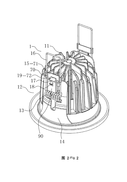
[00107] Referring to Fig. 2 to Fig. 4 of the drawings, an automatic
installation lamp
according to a preferred embodiment of the present invention is illustrated,
wherein the
automatic installation lamp is installed inside an installation hole 501 of a
ceiling 500.
Therefore, the automatic installation lamp 1 comprises a shell body 11 and at
least one
automatic installation mechanism 12, wherein the automatic installation
mechanism 12
comprises an elastic element 13, a fixing base 14 installed on a side face of
the shell body
11, and a support element 16 affixed on an outer side of the fixing base 14.
One end of
the support element 16 is rotatably connected with the side face of the fixing
base 14, and
the elastic element 13 is arranged between the support element 16 and the
fixing base 14
to connect the support element 16 and the fixing base 14 respectively, wherein
the free
end of the support element 16 is adapted to pivotally move towards a lower
portion of the
fixing base 14 through the elastic element 13. The automatic installation
mechanism
further comprises a fixing element 70 arranged on the support element 16 and
having a
first catch element 15, and a limiting element 17, wherein the limiting
element 17 is
rotatably arranged on the side face of the fixing base 14 and is able to slide
up-and-down
along the support element 16. The limiting element 17 comprises a triggering
element 18
17
CA 02941725 2016-08-25
and a second catch element 19, wherein while the triggering element 18 is
activated to
move away from the fixing base 14, the free end of the support element 16 is
able to
overcome a torsion provided by the elastic element 13, so that the free end of
the support
element 16 pivotally folds towards the upper portion of the fixing base 14 as
well as that
the second catch element 19 is hooked on the first catch element 15. In other
words,
while the triggering element 18 is activated to support the limiting element
17 being
moved down or rotated along the support element 16, the second catch element
19 is
detached from the first catch element 15.
[00108] That is to say, the support element 16 is able to perform two
positions, In the
first position, the support element 16 is erect, wherein the free end of the
support element
16 is located on the upper portion of the one end of the support element 16,
and the
second catch element 9 is hooked on the first catch element 15. In the second
position,
the second catch element 19 is detached from the first catch element 15, and
the free end
of the support element 16 is located on a lower portion of the one end of the
support
element 16 and is biased against the shell body 11 or the fixing base 14.
While the
support element 16 is operated through the first position to the second
position, the
triggering element 18 is activated to force the limiting element 17 being
slide down or
rotated along the side face of the fixing base 14, so as to drive the second
catch element
19 being detached from the first catch element 15, and then the free end of
the support
element 16 is pivotally moved towards the lower portion of the fixing base 14
through the
torsion provided by the elastic element 13 in order to complete the second
position. In
other words, while the free end of the support element 16 is able to overcome
the torsion
provided the elastic element 13 (the action force is able to provide on the
support element
16) to move towards the upper portion of the fixing base 14 in order to return
to the first
position, the second catch element 19 is hooked on the first catch element 15.
[00109] The number of the automatic installation mechanism 12 is based on the
requirements. For example, more than one or multiple automatic installation
mechanisms
12 can be provided on the present invention. If only one automatic
installation
mechanism 12 is provided in the present invention, the automatic installation
lamp 1
18
CA 02941725 2016-08-25
cannot be fixedly installed on the ceiling, and the automatic installation
lamp 1 is easy to
fall down from the ceiling. If more than two automatic installation mechanisms
12 are
provided in the present invention, as shown in Fig. 16, which is a seventh
alternative
mode of the automatic installation mechanism according to the preferred
embodiment of
the present invention, four automatic installation mechanisms 12 are provided
to increase
the stability of the installation for the automatic installation lamp 1, but
the
manufacturing cost of the automatic installation lamp 1 will be increased.
Therefore, two
automatic installation mechanisms 12 are normally applied on the automatic
installation
lamp 1, and the two automatic mechanisms 12 are symmetrically arranged on the
automatic installation lamp 1 to provide acceptable stability of the
installation for the
automatic installation lamp 1 and to control the manufacturing cost therefor,
as shown in
Fig. 2 to Fig. 4. Of course, the two automatic installation mechanisms 12 can
be non-
symmetrically arranged on the automatic installation lamp 1, but the stability
of the
installation for the automatic installation lamp 1 may not strong enough.
[00110] The first catch element 15 and the second catch element 19 can be
designed as
any suitable structure. As shown in Fig. 2 to Fig. 4, in the preferred
embodiment of the
present invention, the first catch element 15 is a fixing plate 71, and the
second catch
element 19 is a baffle, wherein the free end of the support element 16 is
pivotally moved
towards the upper portion of the fixing base 14 by overcoming the torsion pf
the elastic
element 13, and then the baffle 72 is hooked on the fixing plate 71 so as to
achieve that
the second catch element 19 is hooked on the first catch element 15. In other
words,
while the triggering element 18 is activated to force the limiting element 17
being rotated
or sliding down along the support element 16, the baffle 72 is moved down or
rotated to
detach from the fixing plate 71, so as to achieve that the second catch
element 19 is
detached from the first catch element 15.
[00111] It is worth mentioning that the first catch element 15 and the second
catch
element 19 can be designed as a through groove and a hook portion, a hook
portion and a
hook portion, and a hook portion and a plate type element.
19
CA 02941725 2016-08-25
[00112] In order to facilitate the installation operation, as shown in Fig. 2
to Fig, 4, in
the preferred embodiment of the present invention, the baffle 72 is a wedge-
shaped
baffle, wherein the wedge-shaped baffle has an inclined surface facing away
from the
fixing base 14, and the fixing plate 71 is touched with the inclined surface
of the baffle 72
to force the baffle 72 moving down until the baffle 72 is hooked on the fixing
plate 71 (as
shown in Fig. 6).
[00113] Obviously, the installation position of the fixing plate 71 and the
baffle 72 is
exchangeable. That is to say, the first catch element 15 can be a baffle 72,
and the second
catch element 19 can be a fixing plate 71, which also can achieve the same
purpose as
mentioned above.
[00114] The number of the first catch element 15 and the second catch element
19 is
based on the requirement, wherein one or more than one first and second catch
elements
15, 19 can be provided in the present invention, However, the support element
16 cannot
be stably fixed on the limiting element 17 by only one first and second catch
element 15,
19, but if more than two first and second catch elements 15, 19 are used to
connect the
support element 16 and the limiting element 17, the stability between the
support element
16 and the limiting element 17 is increased, but the manufacturing cost will
increase also.
Normally, two first and second catch elements 15, 19 are oppositely or
parallelly
arranged with each other, so as to provide a better stability and control the
manufacturing =
cost. As shown in Fig. 2 to Fig. 4, in the preferred embodiment of the present
invention,
the number of the first and second catch element 15, 19 is also one, and the
first and
second catch element 15, 19 are hooked with each other. It is noted that a
width of the
first and second catch element 15, 19 is relatively wider to increase the
stability between
the support element 16 and the limiting element 17.
[00115] The limiting element 17 slidably or rotatably arranged on the side
face of the
fixing base 14 can be any kinds of suitable structure. As shown in Fig. 2 to
Fig. 4, and
Fig. 11 to Fig. 14, in the first to fifth alternative mode of the automatic
installation
mechanism according to the preferred embodiment of the present invention, the
side
surface of the fixing base 14 comprises a box body 90, wherein the limiting
element 17 is
CA 02941725 2016-08-25
slidably or rotatably arranged on the box body 90, and the limiting element 17
is able to
slide up-and-down along the box body 90. The triggering element 18 is arranged
through
a side face of the box body 90, and the triggering element 18 is exposed
through the side
face of the box body 90, and is able to be slide up-and-down along the box
body 90. The
second catch element 19 is arranged through the top portion of the box body 90
and
exposed outside to the box body 90.
[00116] The limiting element 17 is able to slide up-and-down along the box
body 90 or
rotatably arranged on the box body 90, wherein the limiting element 17 can be
installed
on the box body 90 through any suitable structure. As shown in Fig. 2 to Fig.
4 and Fig.
11 to Fig. 14, in the first to fifth alternative mode of the automatic
installation mechanism
according to the preferred embodiment of the present invention, two sides of
the box
body 90 comprises two symmetrically arranged guiding grooves 80, and two sides
of the
limiting element 17 comprises two symmetrically arranged guiding shafts 81,
wherein the
guiding shafts 81 are arranged inside the guiding grooves 80.
[00117] The guiding grooves 80 can be any kinds of suitable structure, as
shown in Fig.
2 to Fig. 4 and Fig. 11 to Fig. 14, in the first to fifth alternative mode of
the automatic
installation mechanism according to the preferred embodiment of the present
invention,
the guiding grooves 80 are L-shaped guiding grooves.
[00118] The limiting element 17 is able to slide up-and-down and arranged on
the side
face of the fixing base 14, wherein while the triggering element 18 is
activated to force
the limiting element 17 being moved down, the second catch element 19 is
detached from
the first catch element 15, and after that, in order to force the limiting
element 17 being
reset, preferably, the automatic installation mechanism 12 further comprises
an elastic
resetting element 43 erectly arranged between the limiting element 17 and the
fixing base
14, and the elastic resetting element 43 is biased against the limiting
element 17 and the
fixing base 14. While an external force applied the triggering element 18 is
released, the
limiting element 17 is moved down to reset to its original position through an
action force
provided by the elastic resetting element 43 to ensure the second catch
element 19 to be
engaged with the first catch element 15. As shown in Fig. 11 to Fig. 13, in
the first to
21
CA 02941725 2016-08-25
third alternative mode of the automatic installation mechanism according to
the preferred
embodiment of the present invention, the elastic resetting element 43 is
erectly arranged
between the limiting element 17 and the box body 90, and the elastic resetting
element 43
is biased against the limiting element 17 and the box body 90.
[00119] The elastic resetting element 43 can be designed as any kinds of
suitable
structure, wherein the elastic resetting element 43 can be a spring or an
elastic body. As
shown in Fig. 11, in the first alternative mode of the automatic installation
mechanism
according to the preferred embodiment of the present invention, the elastic
resetting
element 43 is a spring. As shown in Fig. 12 and Fig. 13, in the second and
third
alternative mode of the automatic installation mechanism according to the
preferred
embodiment of the present invention, the elastic resetting element 43 is a
helicoid spring.
It is noticed that, as shown in Fig. 12, in the second alternative mode of the
automatic
installation mechanism according to the preferred embodiment of the present
invention,
the helicoid spring is erectly arranged between he limiting element 17 and the
box body
90, and the helicoid spring is biased against the lower end of the limiting
element 17 and
the box body 90. As shown in Fig. 13, in the third alternative mode of the
automatic
installation mechanism according to the preferred embodiment of the present
invention,
the helicoid spring is arranged inside the limiting element 17, and arranged
between the
limiting element 17 and the box body 90, and the helicoid spring is biased
against the
limiting element 17 and the box body 90.
[00120] The limiting element 17 is rotatably arranged on the side face of the
fixing base
14. While the triggering element 18 is activated by the external force to
force the limiting
element 17 being rotated downward, the second catch element 19 is detached
from the
first catch element 15. After that, in order to force the limiting element 17
being reset,
preferably, the automatic installation mechanism 12 further comprises an
elastic resetting
element 43 arranged inside the limiting element 17, and arranged between the
limiting
element 17 and the fixing base 14, so as to force the limiting element 17
being rotated
towards the upper portion of the fixing base 14. As shown in Fig. 14, in the
fourth
alternative mode of the automatic installation mechanism according to the
preferred
22
CA 02941725 2016-08-25
embodiment of the present invention, the automatic installation mechanism
comprises an
elastic resetting element 43, wherein the elastic resetting element 43 is
arranged inside
the limiting element 17, and arranged between the limiting element 17 and the
box body
90, so as to force the limiting element 17 being rotated towards the upper
portion of the
fixing base 14.
[00121] Similarly, the elastic resetting element 43 can be designed as any
kinds of
suitable structure. As shown in Fig. 14, in the fourth alternative mode of the
automatic
installation mechanism according to the preferred embodiment of the present
invention,
the elastic resetting element 43 is a helicoid spring.
[00122] As shown in Fig. 15, in the fifth alternative mode of the automatic
installation
mechanism according to the preferred embodiment of the present invention, the
first
catch element 15 is a fixing groove 91 having an opening facing towards one
end of the
support element 16, wherein the second catch element 19 is a baffle 72 (as
shown in Fig.
2), and the free end of the support element 16 is adapted to overcome the
torsion
provided by the elastic element 13 and is pivotally moved towards the upper
portion of
the fixing base 14. The baffle 72 is deposed inside the fixing groove 91 and
is hooked
into the fixing groove 91, wherein the fixing groove 19 is formed close to the
side face of
the fixing base 14, so as to achieve that the fixing groove 91 being hooked
into the first
catch element 15. In other words, while the triggering element 18 is activated
by the
external force to force the limiting element 17 being rotated or slide
downwardly, the
baffle 72 is moved downward or rotated to detach from the fixing groove 91, so
that the
second catch element 19 is detached from the first catch element 15.
[00123] The one end of the support element 16 rotatably connected to the side
face of
the fixing base 14 can be any kinds of suitable structure. As shown in Fig. 2
to Fig. 4, in
the preferred embodiment of the present invention, the elastic element 13 is
rotatably
connected with the side face of the fixing base 14, and is connected with the
one end of
the support element 16 and the fixing base 14 respectively. In other words,
the one end of
the support element 16 is rotatably connected to the side face of the fixing
base 14.
23
CA 02941725 2016-08-25
[00124] More specifically, the elastic element 13 is a hollow structure,
wherein the side
face of the fixing base 14 comprises a pair of symmetrically arranged
protruded portions
41, and two ends of the elastic element 13 are coupled on the two protruded
portions 41,
so as to achieve that the elastic element 13 is rotatably coupled on the side
face of the
fixing base 14.
[00125] The elastic element 13 and the support element 16 are formed as a
whole, and
the elastic element 13 and the support element 16 can be two separated
elements
connected with each other. As shown in Fig. 2 to Fig. 4, in the preferred
embodiment of
the present invention, the elastic element 13 and the support element 16 are
formed as a
whole.
[00126] The elastic element 13 can be any kinds of suitable components, which
is able
to force the free end of the support element 16 being pivotally moved towards
the lower
portion of the fixing base 14. As shown in Fig. 2 to Fig. 4, in the preferred
embodiment
of the present invention, the elastic element 13 is a helicoid spring.
[00127] The support element 16 can be designed as any kinds of suitable
structure, such
as a rod or a sheet. As shown in Fig. 2 to Fig. 4, in the preferred embodiment
of the
present invention, the support element 16 is a U-shaped support element,
wherein two
free ends of the U-shaped support element are connected with the elastic
element 13, and
two ends of the fixing element 70 are arranged on the support element 16.
[00128] The two ends of the fixing element 70 are linked with the support
element 16 by
any kinds of suitable structure. As shown in Fig. 2 to Fig. 4, in the first
preferred
embodiment of the present invention, the two ends of the fixing element 70
comprises
two coupling grooves 42, wherein an opening of the coupling groove 42 is
smaller than
the inner portion of the coupling groove 42, so that two legs of the U-shaped
support
element are coupled inside the coupling groove 42 through the opening.
[00129] The fixing element 70 can be fixedly linked to the support element 16
by a bot,
a nut, the welding skill, or other well-known skills.
24
CA 02941725 2016-08-25
[00130] The triggering element 18 can be designed as any kinds of suitable
structure,
such as a rod or a sheet. As shown in Fig. 2 to Fig. 4 and Fig. 11 to Fig. 14,
in the first to
fourth alternative mode of the automatic installation mechanism according to
the
preferred embodiment of the present invention, the triggering element 18 is a
sheet-
shaped element.
[00131] Referring to Fig. 5 to Fig. 10 of the drawings, an operation process
for the
automatic installation mechanism 12 in the preferred embodiment of the present
invention is illustrated. Fig. 5 shows the automatic installation lamp 1
before the
installation. The support element 16 is in the second position, wherein the
free end of the
support element 16 is located at a position close to the lower portion of the
fixing base 14
b the torsion provided by the elastic element 13. As shown in Fig. 5 to Fig.
7, the free end
of the support element 16 is pivotally moved towards the upper portion of the
fixing base
14 and to overcome the torsion provided by the elastic element 13 (if the
elastic element
13 is a helicoid spring, the action force is a torsion of the helicoid spring)
until the
support element 16 being a upward and erect situation, which is the first
position for the
support element 16 (as shown in Fig. 2 and Fig. 7). In such manner, the
triggering
element 18 of the limiting element 17 is exposed to outside, and the second
catch element
19 of the limiting element 17 is hooked on the first catch element 15 of the
fixing element
70, so as to remain the support element 16 in the first position. Therefore,
the support
element 16 will not be pivotally moved towards the lower portion of the fixing
base 14
through the torsion provided by the elastic element 13 (the first position).
At the same
time, the external force exerted on the support element 16 can be released, as
shown in
Fig. 8 and Fig. 9, and the then the shell body 11 with the support element 16
can be
inserted into the installation hole 501 of the ceiling 500. Since the
triggering elements 18
are extended oppositely with a diameter therebetween slightly larger than a
diameter of
the installation hole 501, the triggering element 18 exposed outside the box
body 90 is
activated by a downward force from the ceiling 500, so that the limiting
element 17 is
slide or rotated along the side face of the fixing base 14, so as to cause the
second catch
element 19 being moved downward and being detached from the first catch
element 15.
In other words, the triggering element 18 is actuated by an opening rim of the
installation
CA 02941725 2016-08-25
hole 501 when the lamp is inserted thereinto. And then, the support element 16
is
pivotally moved downward towards the lower portion of the fixing base 14 by
the torsion
provided by the elastic element 13, so that the ceiling 500 is remained
between the
support element 16 and a lower protruded edge of the shell body 11, as shown
in Fig. 10.
The installation for the automatic installation lamp 1 is completed.
[00132] Referring to Fig. 11 to Fig. 16 of the drawings, the installation
process for the
first and sixth alternative mode of the automatic installation mechanism
according to the
preferred embodiment of the present invention is the same as mentioned above.
[00133] The automatic installation mechanism 12 not only can be installed on
the lamps,
but also can be installed on other objects, such as ornaments.
[00134] Fig. 17 is a detaching process for the automatic installation lamp
according to
the preferred embodiment of the present invention, wherein the automatic
installation
lamp 1 is detached from the installation hole 501 by the support element 16'.
The support
element 16' comprises a guiding end portion 161' and a supporting end portion
162',
wherein one end of the supporting end portion 162' is connected to the elastic
element 13
and the other end of the supporting end portion 162' is connected to the
guiding end
portion 161'. While the automatic installation lamp 1 is installed into the
installation hole
501 and is prepared to detach from the installation hole 501, as shown in Fig.
17, the
automatic installation lamp 1 is moved away from the installation hole 501.
The action
force is applied to the support element 16 by the installation hole 501', so
as to cause the
support element 16' for overcoming the torsion from the elastic element 13,
and then the
support element 16' is pivotally moved towards the upper portion of the fixing
base 14,
so as to force the guiding end portion 161' of the support element 16' being
moved close
to the fixing base 14. While the guiding end portion 161' of the support
element 16' is
touched with the installation hole 501', the guiding end portion 161' of the
support
element 16' is moved along the inner edge of the installation hole 501', and
then the
supporting end portion 162' of the support element 16' is moved close to the
second
catch element 19. That is to say, the first catch element 15 of the supporting
end portion
162' of the support element 16' is moved close to the second catch element 19.
While the
26
CA 02941725 2016-08-25
first catch element 15 and the second catch element 19 are contacted with each
other, the
second catch element 19 is a baffle 72, and furthermore, the baffle 72 is a
wedge-shaped
baffle. The first catch element 15 is touched with the inclined surface of the
baffle 72 in
order to push the baffle being moved downwardly. After that, the baffle 72 is
hooked on
the first catch element 15. In other words, the first catch element 15 is
locked in the first
position. While the support element 16 is moved to leave the installation hole
501, the
first catch element 15 is locked in the first position, so that the support
element 16 will
not be pivotally moved towards the lower portion of the fixing base 14, so as
to prevent
the installation being injured.
[00135] Referring to Fig. 18 to Fig. 20 of the drawings, an eighth alternative
mode of the
automatic installation mechanism according to the preferred embodiment of the
present
invention is illustrated. The different between this alternative mode and the
above
mentioned alternative mode is that the position of the fixing element 70 and
the limiting
element 17 is exchanged. In other words, the limiting element 17 is arranged
on the
support element 16, and the fixing element 70 is arranged on the fixing base
14.
[00136] The limiting element 17 is slidably or rotatably arranged on the
support element
16. Preferably, the limiting element 17 is moved along the support element 16.
The
limiting element 17 further comprises the triggering element 18 and the second
catch
element 19. Preferably, the triggering element 18 is arranged on the limiting
element 17
and is extended away from the side face of the fixing base 14. The limiting
element 17 is
rotatably arranged on the box body 90 and is able to slide up-and-down with
any kinds of
suitable structure. The structure of the limiting element 17 arranged inside
the box body
90 is the same as the structure mentioned above, as shown in Fig. 11 to Fig.
14. The
limiting element 17 is arranged on a top end portion of the fixing base 14.
The fixing
element 70 comprises a first catch element 15, wherein while the second catch
element
19 is hooked on the first catch element 15, the support element 16 is locked
to stop for
rotating towards the lower portion of the fixing base 14. That is to say, the
limiting
element 17 is adapted to force the support element 16 in the first position.
While the
second catch element 19 is detached from the first catch element 15, the
support element
27
CA 02941725 2016-08-25
16 can be pivotally moved towards the lower portion of the fixing base 14. In
this eighth
alternative mode, preferably, the first catch element 15 is a fixing groove
91, and the
second catch element 19 is a baffle 72. The free end of the support element 16
is adapted
to overcome the torsion provided by the elastic element 13 and is pivotally
moved
towards the upper portion of the fixing base 14. The baffle 72 is disposed
inside the
fixing groove 91 and is hooked into the fixing groove 91, wherein the fixing
groove 19 is
moved away from the side face of the fixing base 14, so as to achieve that the
fixing
groove 91 being hooked into the first catch element 15. In other words, while
the
triggering element 18 is activated by the action force to force the limiting
element 17
being rotated or slide downward, the baffle 72 is moved downward or rotated to
detach
from the fixing groove 91, so that the second catch element 19 is detached
from the first
catch element 15. While the first catch element 15 and the second catch
element 19 are
hooked with each other, the second catch element 19 can be protected inside
the fixing
groove 91, so as to prevent the second catch element 19 being damaged.
[00137] An installation method for the automatic installation lamp comprises
the
following steps:
[00138] 1. Prevent the free end of the support element 16 being pivotally
moved towards
the lower portion of the fixing base 14. In other words, the support element
16 is
remained in the first position. A restoring force is applied on the support
element 16 by
the elastic element 13 to force the free end of the support element 16 being
pivotally
moved to the upper portion of the fixing base 14. The second catch element 19
is adapted
to lock with the first catch element 15, so as to stop the free end of the
support element 16
being pivotally moved towards the lower portion of the fixing base 14. In
other words,
the restoring force provided by the elastic element 13 is adapted to support
the limiting
element 17, wherein the second catch element 19 is supported by the limiting
element 17,
so that the first catch element 1 is blocked by the second catch element 19.
That is to say,
the second catch element 19 is hooked on the first catch element 15.
Preferably, the first
catch element 15 is a fixing plate 71, and the second catch element 19 is a
baffle 72. In
other words, the baffle 72 is biased against the fixing plate 71 to overcome
the torsion
28
CA 02941725 2016-08-25
exerted on the support element 16 provided by the elastic element 13, so as to
maintain
the support element 16 in the first position.
[00139] 2. Remove the second catch element 19, and the second catch element 19
is not
stopped by the first catch element 15 of the support element 16. An external
force is
exerted to the limiting element 17 to overcome the torsion exerted on the
limiting element
17 by the elastic resetting element 43, so as to drive the first catch element
15 being un-
blocked by the second catch element 19, wherein the guiding shafts 81 of the
limiting
element 17 is driven to move towards the guiding grooves 81, so that the
triggering
element 18 is guided to move away from the first catch element 15, and then
the second
catch element 19 is detached from the first catch element 15. It is worth
mentioning that
the external force is exerted on the triggering element 18, so that the
limiting element 17
is able to overcome the torsion provided by the elastic resetting element 43.
The
triggering element 18 is activated to move the limiting element 17, and the
first catch
element 15 of the limiting element 17 is moved to un-blocked by the second
catch
element 19, so as to release the first catch element 15.
[00140] 3. Pivotally move the support element 16, and the free end of the
support
element 16 is pivotally moved towards the lower portion of the fixing base 14.
According
to the preferred embodiment of the present invention, the automatic
installation lamp 1 is
supported by the ceiling 500. While the second catch element 19 is moved to
detach from
the first catch element 15, the free end of the support element 16 is
pivotally moved
towards the lower portion of the fixing base 14 by the restoring force
provided by the
elastic element 13. While the free end of the support element 16 is touched
with the
ceiling 500, the resetting force provided by the elastic element 13 is adapted
to force the
free end of the support element 16 to support the fixing base 14, and until
the protruded
edge of the fixing base 14 is touched with the installation hole 501. The
automatic
installation lamp 1 can be fixed on the installation hole 501. The automatic
installation
lamp 1 is installed completely.
[00141] 4. Lift up the fixing base 14, and force the lower portion of the
fixing base 14
being touched with the ceiling 500, so as to fix the automatic installation
lamp 1 on the
29
CA 02941725 2016-08-25
ceiling 500. The free end of the support element 16 is blocked for rotating
towards the
lower portion of the fixing base 14 as well as that the support element 16
being touched
with the ceiling 500. The restoring force provided by the elastic element 13
is exerted on
the free end of the support element 16 to rise up the fixing base 14. The
automatic
installation lamp 1 is fixed on the ceiling 500, and the fixing base 14 of the
automatic
installation lamp 1 is raised up to abut the ceiling 500, so as to fix the
automatic
installation lamp 1 on the ceiling. While the free end of the support element
16 is
contacted with the ceiling 500, the restoring force provided by the elastic
element 13 is
adapted to raise up the fixing base 14 until the protruded edge of the fixing
base 14 is
touched with the installation hole 501. Therefore, the automatic installation
lamp 1 is
fixed into the installation hole 501. And, the automatic installation lamp 1
is installed
completely.
[00142] It is worth mentioning that before the step 1 of the installation
method for the
automatic installation lamp 1, the installation method further comprises a
step a: pivotally
move the free end of the support element 16 to achieve the first position. The
support
element 16 is in the erect situation. The external force is exerted on the
support element
16 to force the free end of the support element 16 to overcome the restoring
force
provided by the elastic element 13, so as to force the free end of the support
element 16
being pivotally moved towards the upper portion of the fixing base 14. The
first catch
element 15 arranged on the support element 16 is biased against the second
catch element
15 to reach the first position, wherein while the first catch element 15 is
touched with the
second catch element 19, the second catch element 19 is endured by a pressure
provided
by the first catch element 15, so that the second catch element 19 is moved to
a position
that the second catch element 19 cannot be locked by the first catch element
15. The
second catch element 19 is adapted to overcome the restoring force provided by
the
elastic resetting element 43 to drive the guiding shaft 81 of the limiting
element 17 being
moved towards the guiding groove 81. While the first catch element 15 is
biased against
the second catch element 19, the restoring force provided by the elastic
resetting element
43 is adapted to force the first catch element 15 being locked by the second
catch element
19.
CA 02941725 2016-08-25
[00143] It is worth mentioning that the installation method for the automatic
installation
lamp 1 further comprises a step 5 after the step 4: Remove the second catch
element 19,
and the restoring force provided by the elastic resetting element 43 is
exerted on the
triggering element 18 to force the triggering element 18 moving towards the
guiding
groove 80, so that the second catch element 19 return to be hooked on the
first catch
element 15.
[00144] Referring to Fig. 21 of the drawings, an automatic installation device
for an
automatic installation lamp' according to a preferred embodiment of the
present
invention is illustrated, wherein the automatic installation device comprises
a shell body
10', an automatic switch 20', and a lock unit 30'.
[00145] The shell body 10' comprises a flat and circle shaped base 11', two
protruded
fixing plate 12' symmetrically arranged, and a ring-shaped fixing wall 13'
arranged
between two fixing plate 12', wherein the base 11' has a circle and plate
shaped, and an
outer edge of the base 11' is slightly protruded, and the outer edge of the
base 1 1 ' is
inwardly and downwardly extended to from a base groove 110', so that the
automatic
installation lamp 1' can be used in different space and environment, and the
automatic
installation lamp 1' can be incorporated with other external components, so as
to improve
the flexibility of the use. The lower portion of the fixing plate 12' is
closely connected
with the ring-shaped fixing wall 13', and the upper portion of the fixing
plate 12' is
slightly incurvated, and two through hole 120' are parallelly arranged on a
position close
to the two fixing plates 12' respectively, wherein the through hole 120' is
adapted to
install the lock unit 30'. The shell body 10' further comprises a connection
portion 14'
adapted to install the automatic switch 20', wherein the connection portion
14' comprises
an inwardly extended structure adapted to install the automatic switch 20'.
[00146] Referring to Fig. 22 to Fig. 24, the automatic switch 20' comprises a
cover 2 1 ',
an operation cavity 22', a trigger arm 23', a moving block 24', and an elastic
element 25',
wherein outer two sides of the cover 21' are outwardly extended to form outer-
side
stations 211' adapted to support the automatic switch 20' being installed on
the shell
body 10', and the front end of the cover 21' comprises a cover opening 212'.
It is noticed
31
CA 02941725 2016-08-25
that the uppermost horizontal portions of the cover opening 212' are not
connected with
each other, so that the cover opening 212' is formed as a T-shaped, so as to
provide a
rotation space for the trigger arm 23'. Two sides of the rear and inner
portion of the cover
opening 212' comprises two horizontally extended inner-side stations 213' to
limit the
trigger arm 23' only being operated in a rotation manner, so as to prevent the
trigger arm
23' being operated towards the front and back direction. The cover 21' further
comprises
a inner-side slot 214' obliquely and vertically formed on the inner-side
station 213',
wherein the inner-side slot 214' is adapted to incorporate with the operation
cavity 22'.
The cover 21' further comprises a bottom boss 215' formed inside the cover
opening
212'. It is worth mentioning that the cover 21' and the operation cavity 22'
are able to be
incorporated with each other, and in such manner, the bottom boss 215' of the
cover 21'
will be connected with a bottom portion of the operation cavity 22'. The
operation cavity
22' comprises two P-shaped grooves 221' formed on two inner side walls of the
operation cavity 22' to provide a operation space for the trigger arm 23'. The
operation
cavity 22' further comprises two outer-side protruded portions 222' formed on
the two
outer side of the operation cavity 22' and close to the P-shaped grooves 221',
adapted to
fixedly connect with the cover 21'. And, the upper portion of the operation
cavity 22'
comprises an upper opening 223' adapted to lock the moving block 24' and an
elastic
element 25' adapted to support the moving block 24' moving back to its
original position.
The operation cavity 22' further comprises a block element 224' adapted to
place and
support the elastic element 25', and the trigger arm 23' is placed on the
uppermost
portion of the operation cavity 22'. The trigger arm 23' comprises an elliptic
cam 231' ,
an arc-shaped tension arm 232' frontwardly extended from the elliptic cam
231', and two
cylindrical fixing components 233' formed on two sides of the elliptic cam
231', wherein
the fixing components 233' are adapted to support the trigger arm 23' being
installed into
the operation cavity 22'.ln addition, the rear end of the elliptic cam 231' is
a hollow
structure, and the trigger arm 23' further comprises a guiding component 234'
formed
inside the hollow structure to control the moving block 24' moving within a
particular
space. The moving block 24 is formed between the arc-shaped tension arm 232',
the
fixing component 233', and the guiding component 234', wherein the moving
block 24'
is a long type structure, and the bottom two sides of the moving block 24' is
defined as a
32
CA 02941725 2016-08-25
=
resetting element 241' outwardly extended to from an inclined structure. The
resetting
element 241' is adapted to support the trigger element 23' to move back to its
original
position. The front end of the moving block 24' comprises a locating slot 242'
inwardly
extended from the moving block 24', wherein the locating slot 242' is adapted
to
incorporate with the guiding element 234' to support the moving block 24'
operating
within a suitable direction and space. The moving block 24' further comprises
a
supporting element 243' having an arc-shaped structure formed on the upper
portion of
the moving block 24', and a supporting slot 244', formed as a track, to
support the
moving block 24' operating only in an up-and-down direction. The elastic
element 25' is
formed under the moving block 24' and inside the operation cavity 22', wherein
the
elastic element 25' is able to provide torsion to the trigger arm 23', so as
to force the
trigger arm 23' being moving back to its original position. Therefore, the
elastic element
25' is a component which can provide certain amount of resetting force, so in
the present
invention, the elastic element 25' is a spring which is easy to obtain and
having low in
cost.
[00147] It is noticed that a top portion of the cover 21' is designed as an
inclined
structure, wherein the cover 21' is connected with the ceiling 50' during the
installation
procedure, so that the inclined structure can prevent the automatic switch 20'
being
locked by the installation hole 51' during the installation procedure.
[00148] Referring to Fig. 21 to Fig. 24, two lock unit 30' are arranged on two
bottom
sides, left side and right side, of the automatic switch 20', wherein the lock
unit 30'
comprises an elastic portion 31', a pair of supporting arm 32', a locking
portion 33', a
fixing portion 34', and a bending portion 35', wherein the lock unit 30' is
made of elastic
metal, and the elastic portion 31' has the same function as the spring adapted
to support
the automatic switch 20' being operated during installation procedure and
being returned
back to its original situation. The supporting arm 32' is parallelly extended
from two ends
of the elastic portion 31', wherein the supporting arm 32' not only is adapted
to support
the automatic installation lamp 1' being installed on the installation hole
51', but also
able to improve the strength and stability of the installation, wherein one
end of the lock
33
CA 02941725 2016-08-25
unit 30' is fixed on the base II', and the other end of the lock unit 30' is a
movable lever,
so the supporting arm 32' is used to be determined the amount of action force
provide on
the lock unit 30'. Therefore, the lock unit 30' can be made of variable
elastic steels
having better hardness and resetting capacity. In addition, the two supporting
arms 32'
have the larger strength and durability while the two supporting arms 32 are
parallelly
arranged. In order to facilitate the inspection and maintainability, the
locking portion 33'
is arranged between tow parallelly arranged supporting arms 32'. While the
length of the
supporting ram 32' is reduced to a certain distance, the rear end of the
supporting arm 32'
can be a locker, so as to maintain the two supporting arms 32' being
parallelly arranged
and ensure the safety use of the present invention. Besides, the locking
portion 33' is
arranged at a position that the locking portion 33' can lock with the moving
block 24'
while the moving block 24' is upwardly protruded to contact with the locking
portion
33', wherein the locking portion 33' is used to pull up on a particular
position which can
be determined as an anticipation position before the installation procedure,
so as to
improve the efficiency and the yield rate of the installation procedure. In
order to make
sure that the structure of the lock unit 30' will not be affected by the
external force or
objects, after the two supporting arms 32' are outwardly extended to a
predetermined
distance, the U-shaped fixing portion 34' is provided to make the lock unit
30' to form a
close structure, so that the lock unit 30' is in a stable structure.
[00149] In order to ensure the structure and the stability of the present
invention by
incorporating the physical structure and mechanics principle thereof, the
bending portion
35' is a labor-saving structure, and the inwardly extended bending portion 35'
is able to
reduce the distance between the locking portion 33' and the moving block 24',
and the
distance of the application of a force is reduced, so that the time and
strength of the
application of the force is relatively reduced, and the total energy-consuming
of the lock
unit 30' is reduced also, so as to achieve the labor-saving purpose. The
bending portion
35' is an auxiliary device, wherein since the automatic installation lamp 1'
is in mass
production, the specifications and styles of the bending portion 35' are
fixed. Since the
automatic installation lamp 1 can be installed in different size of
installation hole 51', but
the thickness of the different kinds of installation holes 51' are always
different.
34
CA 02941725 2016-08-25
Although, the thickness of the installation hole 51' will not affect the
successful rates and
the stability of the installation procedure, the ceiling 50' having a hardness
depth needs to
consume more energy during the installation procedure, or other unobvious
effects may
affect the installation procedure. Therefore, the bending portion 35' is able
to ensure the
rear end of the lock unit 30' being close to the circumference of the shell
body 10', and
the lock unit 30' can be remained in an anticipation position before
installation
procedure, so as to ensure the operation rate and successful rate of the
installation
procedure. The bending portion 35' also can be determined as a reinforcement
structure.
Although, the outside of the installation hole 51' look like the same, but
most of people
don't know the installation situation inside the installation hole 51'. The
housing
structure or other reasons may affect the installation condition of the
installation hole 51',
so that the successful rate of the installation procedure may be affected.
Therefore, the
bending portion 35' provides an adjustable and elastic space for the lock unit
30', so that
the successful rate of the installation procedure will not be affected by
other external
facts, so as to improve the installation stability of the installation
procedure.
[00150] As shown in Fig. 25, it is worth mentioning that before the
installation method
of the automatic installation device, the two bending portions 35' are pulled
upwardly,
and the locking portion 33' of the lock unit 30' is locked by the moving block
24' of the
automatic switch 20' in a fixed position.
[00151] As shown in Fig. 26, after the locking portion 33' of the lock unit
30' is locked
by the moving block 24' of the automatic switch 20', the automatic
installation lamp l' is
faced towards the installation hole 51' of the ceiling 50', and in such manner
that the two
automatic switch 20' must be installed on a corresponding position, so the
straight line
distance between the two automatic switch 20' is determined as a circle
diameter of the
automatic installation lamp 1', so that the outer edge of the automatic switch
20' is
adapted to biased against the inner circumference of the installation hole
51', and the
automatic installation lamp 1' is pushed upwardly to activate the operation of
the trigger
arm 23', so as to activation the operation of the installation procedure. The
operation
procedure of the automatic switch 20' is shown in Fig. 26. At first, while the
trigger arms
CA 02941725 2016-08-25
23' are not operated, the trigger arms 23' are arranged horizontally with
respect to the
moving block 24', and the trigger arms 23' are arranged at a position where is
protruded
with respect the cover opening 211' of the cover 21', so that the trigger arms
23 are also
arranged horizontally with respect the cover opening 211'. In addition, the
moving block
24' is also protruded with respect to the upper opening 223' of the operation
cavity 22',
and the moving block 24' is horizontal to the upper opening 223'. Therefore,
while the
automatic installation lamp 1 is pushed into the installation hole 51', the
trigger arms 23'
are biased against an inner wall 52' of the installation hole 51', so that an
arc-shaped
tension arm 232' of the trigger arm 23' is downwardly operated by the anti-
reaction force
provided by the inner wall 52' of the installation hole 51', and then the
elliptic cam
231 'of the trigger arms 23' is operated in an opposite direction with respect
to the arc-
shaped tension arm 232', so that the moving block 24' is activated to operate
downwardly and is dis-meshed with the lock unit 30', and finally the lock unit
30' will
reset to its original position.
[00152] Referring to Fig. 27 of the drawings, while the shell body 10' of the
automatic
installation lamp 1 is detaching from the ceiling 50', the automatic
installation lamp l' is
pulled down by an external force, so as to destroy the original dynamic
equilibrium.
While the shell body 10' is continuously pulled down, the supporting arms 32
only can
move downwardly due to that the lock unit 30' is moved downwardly. While the
shell
body 10' of the automatic installation lamp I' is continuously moved down, the
automatic switch 20' is exposed, and the outer wall of the cover 21' is not
blocked by the
inner wall of the installation hole 52', so that the trigger arms 23' can be
outwardly
extended to return to its original situation. In addition, the elliptic cam
231' is activated to
rotate to drive the movement of the moving block 24'. In such manner, the
elastic
element 25' is compressed and then released to provide torsion to force the
moving block
24' being moved upwardly. The lock unit 30' is moved to pass through the
installation
hole 51' while the automatic installation lamp 1' is continuously moved
upwardly.
Furthermore, the bending portion 35' is an arc-shaped structure, so no angle
will generate
between the lock unit 30' and the installation hole 51'. Therefore, the
automatic
36
CA 02941725 2016-08-25
installation lamp 1' will not be locked within the installation hole 51' while
the automatic
installation lamp 1' is detaching from the installation hole 51'.
[00153] Referring to Fig. 28 of the drawings, while the supporting arms 32' of
the lock
unit 30' is operated to return to its original position, the installation hole
52' of the ceiling
50' only can allow the shell body 10' being passed through, the supporting
arms 32' can
not pass through the installation hole 51' due to the length thereof, and the
size of the
base 11' is also larger than the installation hole 51', so that a downward
resetting force
provided by the lock unit 30' is exerted on the automatic installation lamp
l', and then an
anti-resetting force will generate on the base 11', wherein the resetting
force and the anti-
resetting force have the same amount with opposite direction, and the dynamic
equilibrium will generate on the automatic installation lamp 1' due to the
Newton's third
law of motion, so that the automatic installation lamp l' is fixed on the
ceiling 50'
[00154] One skilled the art will understand that the embodiment of the present
invention as shown in the drawings and described above is exemplary only and
not
intended to be limiting.
[00155] It will thus be seen that the objects of the present invention have
been fully and
effectively accomplished. The embodiments have been shown and described for
the
purposes of illustrating the functional and structural principles of the
present invention
and is subject to change without departure from such principles. Therefore,
this invention
includes all modifications encompassed within the spirit and scope of the
following
claims.
37