Note: Descriptions are shown in the official language in which they were submitted.
CA 02942400 2016-09-20
SEED METERING CASSETTE FOR SEEDING IMPLEMENT
BACKGROUND OF THE INVENTION
The present invention relates to farm implements and, more particularly, to a
seed
metering cassette for a seeding implement, such as an air seeder.
Air seeders are commonly towed by tractors to apply seed, fertilizer, or micro-
nutrients
or any granular product to a field. For purposes of this application "seeding"
shall include the
application or deposition of any granular or particulate material onto a
field, and "seed" shall
include seed, fertilizer, micronutrients, or any other granular material that
may be applied onto a
planting surface, farm field, seedbed, and the like. It is generally
advantageous to tow an air
seeder in combination with a tilling implement, one behind the other, to place
the seed and
fertilizer under the surface of the soil. An air seeder has as its central
component a wheeled seed
cart which comprises one or more frame-mounted seed tanks for holding product,
generally seed
or fertilizer or both. Air seeders also generally include a volumetric
metering system operable to
measure a fixed volume of seed per unit of linear distance and a pneumatic
distribution system
for delivering the product from the tank to the soil.
The volumetric metering system is configured for distribution of product from
the tank to
the distribution headers of the seed tubes. The metering system typically
includes a meter roller
assembly employing augers or fluted cylinders (meter rollers) situated in a
meter box assembly
secured below the tank.
Typically the meter box will have a series of outlets known as runs that each
leads to the
distribution lines of the pneumatic distribution system. The pneumatic
distribution system
(00366432.DOC \ 1
CA 02942400 2016-09-20
generally includes an air stream operable to carry product metered by the
meter roller assembly
through the distribution lines to a series of secondary distribution manifolds
("headers"), which
in turn distribute product to a group of ground openers mounted on the seeding
implement
operable to place seed in the ground. The ground openers are configured to
evenly deliver the
product to the span of ground (the "seedbed") acted upon by the seeding
implement.
To reduce manufacturing costs and eliminate consumer confusion is customizing
an air
seeder, most manufacturers offer a seed metering assembly in which the meter
box and the fluted
meter roller that are sized to meter granular material to a preset number of
secondary headers.
One of the drawbacks of such a construction is that not all implements require
or have the preset
number of secondary headers. For those implements having fewer secondary
headers, sections
of the seed metering assembly must be capped off. The result is that the
consumer is required to
purchase a seed metering assembly that may be larger than the consumer
requires.
Additionally, for some implements, there can be some inconsistency in the
number of
outlets of the secondary headers. This inconsistency is generally the result
of the implement
having a particular frame configuration that may be required to achieve a
particular transport
configuration. Since the meter roller meters granular material to each of the
secondary headers
at the same metering rate, the amount of granular material per outlet will be
higher for those
secondary headers having a fewer number of outlets. As a result, the seedbed
serviced by the
ground opener units that are fed by the headers having fewer outlets will be
over-seeded
compared to the seedbed serviced by the other ground opener units. This
discrepancy in the
application of granular material, which heretofore has been generally ignored,
can ultimately
lead to inconsistent seeding and thus inconsistent per row crop yields.
{00366432 DOC 1} 2
CA 02942400 2016-09-20
SUMMARY OF THE INVENTION
The present invention is directed to a modular seed metering assembly or unit
in which
several such modular units can be used to build a seed metering apparatus that
is matched to a
particular implement. Each modular assembly is a stand-alone unit that can be
controlled to
meter granular material at a metering speed that is independent of the
metering speed of the other
units of the seed metering apparatus. Each seed metering unit is selectively
driven by a common
drive member, such as a drive shaft. Thus, when a seed metering unit is
engaged with the drive
member, the unit will meter granular material. On the other hand, when the
seed metering unit is
not engaged with the drive member, the metering unit will not meter granular
material. Hence,
the present invention also provides a seed metering apparatus that provides
effective sectional
control. Moreover, when an engaged seed metering unit is disengaged, the
response time is
nearly instantaneous. Thus, metering by the disengaged seed metering unit
ceases nearly
immediately.
Accordingly, in one aspect of the invention, a seed metering apparatus is
provided that is
capable of metering measured amounts of granular material to a number of
secondary headers
using a series of modular seed metering units that can be independently
controlled to provide
sectional control during seeding.
In a further aspect, each metering unit can be caused to run faster or slower
than other
metering units of the metering apparatus to provide additional control in the
metering of seed,
fertilizer or other granular material.
In accordance with another aspect of the invention, a modular seed metering
unit or seed
metering cassette is provided that allows a seed metering unit to be added or
removed from a
(00366432 DOC \ 3
CA 02942400 2016-09-20
seed metering apparatus as a stand-alone component. In this regard, the needed
number of seed
metering units for a given air seeder can be achieved by stacking together
modular units. As
such, the present invention allows an air seeder to be built using modular
components rather than
using a single, fixed length meter roller.
It is therefore an object of the invention to provide a seed metering
apparatus with
sectional control and, more particularly, sectional control with a quick
response time.
It is another object of the invention to provide a cassette-based seed
metering unit in
which multiple such units could be arranged together to form a seed metering
apparatus.
Other objects, features, aspects, and advantages of the invention will become
apparent to
those skilled in the art from the following detailed description and
accompanying drawings. It
should be understood, however, that the detailed description and specific
examples, while
indicating preferred embodiments of the present invention, are given by way of
illustration and
not of limitation. Many changes and modifications may be made within the scope
of the present
invention without departing from the spirit thereof, and the invention
includes all such
modifications.
BRIEF DESCRIPTION OF THE FIGURES
Preferred exemplary embodiments of the invention are illustrated in the
accompanying
drawings in which like reference numerals represent like parts throughout.
In the drawings:
FIG. 1 is an isometric view of a seed metering apparatus for use with an air
seeder
according to one embodiment of the present invention;
(00366432 DOC \ ) 4
CA 02942400 2016-09-20
FIG. 2 is a side elevation view of the seed metering apparatus of FIG. 1;
FIG. 3 is a rear view of one seed metering unit of the seed metering apparatus
of FIG. 1;
and
FIGS. 4-5 are views of a bulk fill hopper of the seed metering apparatus of
FIG. 1
according to another aspect of the invention.
DETAILED DESCRIPTION
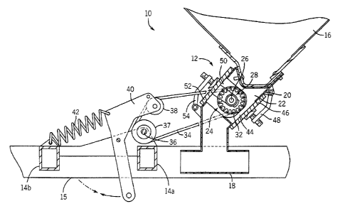
Turning now to FIG. 1, a seed metering apparatus 10 for an air seeder (not
shown)
includes a series of seed metering units 12 each mounted to a seeder frame 14,
e.g., frame
crossbar 14a, adjacently below a hopper 16. In one embodiment, the frame 14
includes the
aforementioned crossbar 14a and an upland crossbar 14b that are interconnected
between a pair
of parallel rails 15. Each seed metering unit 12 is designed to meter granular
material, e.g., seed
or fertilizer, from the hopper 16 to one or more delivery conduits 18. The
hopper 16 is mounted
to the parallel rails 15 in a conventional mariner, i.e., by mounts 17. It
will thus be appreciated
that the seed metering units 12 are supported at one end by a connection to
crossbar 14a and
supported at an opposite end by hopper 16.
As will be described more fully below, each seed metering unit 12 is a self-
contained,
modular, and individual assembly. In this regard, the number of seed metering
units for a given
seed metering apparatus may vary from that shown in figures. Moreover, the
modularity of the
seed metering units 12 allows the number of seed metering units to be matched
to the number of
secondary headers (not shown) of the air seeder. Further, the present
invention allows seed
metering units to be added to a given air seeder as needed. Additionally, as
will be described,
each metering unit can be independently controlled. Thus, each metering unit
can meter granular
t00366432 DOC \ ) 5
CA 02942400 2016-09-20
material at a speed that is independent of the meter rates of other metering
units. This is
particularly advantageous for air seeders having secondary headers with
differing number of
outlets.
With additional reference to FIGS. 2 and 3, each metering unit 12 has a
bulkhead 20 that
defines a cavity 22 containing a meter roller assembly 24. The meter roller
assembly 24 includes
a fluted rotor 26 that is rotatably mounted to bulkhead 20 by a bearing
assembly 28, which
includes a bearing 30. 0-rings 31 provide sealing of the rotor 26 in the
bulkhead 20. As known
in the art, when the rotor 26 rotates, the fluted rotor 26 captures granular
material as it falls from
the hopper 16 and passes the captured granular material to the delivery
conduits associated with
the seed metering unit 12.
Each fluted rotor 26 further has a pulley 32 that is mounted to, or integrally
formed with,
the rotor 26. In the illustrated example, an end of the rotor 26 passes
through an opening 33
formed in the bulkhead. The pulley 32 is attached to the exposed portion of
the rotor 26. Each
pulley 32 is caused to rotate by a drive belt 34 that is entrained about the
pulley 32 and a drive
shaft 36. As shown particularly in FIG. 1, a series of pulleys 37 are mounted
to the drive shaft
36 and thus rotate with rotation of the drive shaft 36. Each drive belt is
each entrained about a
respective pulley 32 and a respective drive pulley 37. In this regard, a
single and common drive
shaft 36 is used to cause rotation of the fluted rotors 26. In a preferred
embodiment, drive belts
34 are each V-belts, but it is understood that other types of elongated
members could be used,
such as chains, links, cable, and the like.
When drive shaft 36 rotates, the drive belts 34 are caused to translate around
the drive
shaft and their respective pulleys 32 to cause rotation of the fluted rotor 26
and ultimately
( 00366432 DOC 1) 6
CA 02942400 2016-09-20
metering of granular material passed from the hopper 16 to the seed metering
unit 12. The
present invention, however, provides sectional control of the seeding process.
In this regard,
each metering unit 12 also includes an idler roller 38 that is mounted to a
bell crank 40. The bell
cranks 40 are pivotably mounted to the seeder frame 14 in a conventional
manner. In addition to
being entrained about pulley 32 and drive shaft 36, each drive belt 34 is also
entrained about a
respective idler roller or pulley 38. Each idler roller 38 is designed to add
or remove tension to
its associated drive belt 34. When the drive belt 34 is tensioned, rotation of
the drive shaft 36
will cause translation of the drive belt 34 and thus rotation of the pulley
32. On the other hand,
when there is sufficient slack in the drive belt, the drive belt 34 will be
loosely entrained about
the drive shaft 36 and, as a result, rotation of the drive shaft 36 will not
cause translation of the
drive belt 34. Accordingly, when there is sufficient slack in the drive belt
34, rotation of the
drive shaft 36 will not cause rotation of the fluted rotor 26. It will thus be
appreciated that
sectional control can be achieved by selectively disengaging a selected seed
metering unit from
tensioned engagement with the drive shaft 36.
Movement of the idler roller 38 is controlled by a respective bell crank 40.
In this regard,
the bell crank 40 is movable between an engaged position and a disengaged
position. A
tensioning spring 42 is interconnected with the seeder frame 14, e.g.,
crossbar 14b, and the bell
crank 40 to bias the bell crank 40, and thus the drive belt 34, in the engaged
position. In a
preferred embodiment, each bell crank 40 is linked to a drive input (not
shown) that is operative
to move the bell crank 40 between the engaged and disengaged positions. The
drive input may
be any known or to be developed input device. For example, a hydraulic,
pneumatic,
mechanical, or electrical circuit could be used to move the bell crank 40
between the engaged
(00366432 DOC \) 7
CA 02942400 2016-09-20
and disengaged positions. Moreover, it is contemplated that each input device
may be controlled
via an operator input or controlled automatically, such as by a GPS-based
control.
In one preferred embodiment, a single input device is used to simultaneously
move a set
of bell cranks 40 to effectuate engagement/disengagement of a set of seed
metering units 12.
This "tying" of multiple seed metering units 12 to a single input device
allows all of the seed
metering units 12 feeding granular material to a given secondary header to be
started or stopped
at the same time. While the seed metering units can be grouped together and
thus controlled by a
shared input device, the present invention is not so limited. Each seed
metering unit, or a given
group of seed metering units, can be selectively disengaged from the common
drive shaft to
effectively stop the metering by the selected seed metering units. It will
thus be appreciated that
the invention provides sectional control without mechanical gates or similar
devices.
Additionally, the modularity of the seed metering units and the independent
coupling of
each seed metering unit to the drive shaft effectively provides a cartridge or
cassette that can be
added on an as-needed basis to a given air seeder. Moreover, because each seed
metering unit is
a separate stand-alone cartridge, metering units will different
characteristics can be used on a
single air seeder. For example, a larger pulley 32 could be used for one seed
metering unit to
provide metering at a slower rate and a smaller pulley 32 could be used for
another seed
metering unit to provide metering at a faster rate. This modularity could be
particularly
advantageous in instances in which it is desirable to meter seed and
fertilizer at different rates.
Referring briefly again to FIG. 2, the bulkhead 20, in one preferred
embodiment, has a
pair of service openings. One service opening is a drain port 44 that is
formed in the lower end
of the bulkhead 20. The drain port 44, when opened, allows granular material
to be drained from
{00366432.DOC \ ) 8
CA 02942400 2016-09-20
the hopper. The drain port 44 is selectively opened and closed by a drain door
or panel 46 that is
pivotably mounted to the hopper 16 by linkage 48.
Generally opposite the drain port 44 is an access opening 50. The access
opening 50 is
sized to allow removal of the rotor 26 when disconnected from the rotor
bearing assembly 28.
The access opening 50 is opened and closed by an access panel 52 that is
pivotably mounted to a
lower end of the bulkhead 20 by linkage 54.
Referring now to FIGS. 4-5, hopper 16 has an internal volume 56 defined by a
front panel
58, rear panel 60, and side panels 62, 64. The hopper 16 further has a lower
panel 66. The panels
are interconnected in a known manner or could be integrally formed as a single
unit. In one
preferred embodiment, the lower panel 66 includes a series of openings 68. The
number of
openings 68 is matched to the number of seed metering units 12. It will thus
be appreciated that
the invention provides a hopper 16 that can be quickly serviced to provide a
number of discharge
openings matched to the number of seed metering units. In one embodiment, each
opening 68
can be closed as needed by a cover plate 70 which is secured to the lower
panel 66 using
conventional fasteners, such as wing nuts 72. Alternately, it is contemplated
that the lower panel
has linearly spaced knockouts. When a knockout is removed, a corresponding
opening in the
lower panel is exposed. In one embodiment, the knockouts cannot be reattached
to the lower
panel; although, other embodiments may have re-attachable knockouts.
Additionally, it is
contemplated that other types of devices may be used to selectively form
discharge openings in
the lower panel, such as slidable or removable doors, louvers, and the like.
(00366432 DOC 1) 9
CA 02942400 2016-09-20
While a drive belt and pulley arrangement is shown in the figures and has been
described
above, it is understood that other types of arrangements could be used, such
as gears, clutches,
individual electric motors or hydraulic motors, and the like.
From the foregoing it will be appreciated that the present invention provides
a seed
metering apparatus capable of metering measured amounts of granular material
to a number of
secondary headers using a series of modular seed metering units that can be
independently
controlled to provide sectional control during seeding. Each metering unit can
be caused to run
faster or slower than other metering units of the metering apparatus.
Moreover, the modularity
of the present invention allows each seed metering unit to be added or removed
from the seed
metering apparatus as a stand-along cartridge or cassette. It will also be
appreciated that the
present invention provides sectional control with a quickened response time.
When the drive
belt for a given seed metering unit is loosened as a result of its bell crank
being moved to the
disengaged position, the meter roller for the seed metering unit will stop
nearly instantaneously.
As such, the present invention avoids the shut-off lag times typically
associated with sectional
control.
Many changes and modifications could be made to the invention without
departing from
the spirit thereof. The scope of these changes will become apparent from the
appended claims.
(00366432 DOC \; 10