Note: Descriptions are shown in the official language in which they were submitted.
TITLE: CARBONATE-BONDED CONSTRUCTION PRODUCTS FROM STEEL-MAKING
RESIDUES AND METHOD FOR MAKING THE SAME
10 FIELD
[0002] The present subject-matter relates to building products and
materials, and
more particularly to building products and materials that include steel slag.
BACKGROUND
[0003] In the construction industry, various products are used,
including concrete
blocks. Such concrete blocks are precast and are composed inter alia of coarse
granular
material (the aggregate or filler) embedded in a hard matrix of material (the
cement or
binder), which fills the spaces between the aggregate particles and glues them
together.
The binder that is commonly used is Portland cement.
[0004] The cement industry is a primary producer of carbon dioxide
(CO2), which is
recognized as a major greenhouse gas. Thus, disadvantageously, large amounts
of CO2
are produced by the chemical reactions occurring in the manufacture of cement.
SUMMARY
[0005] It would thus be highly desirable to be provided with a system
or method that
would at least partially address the disadvantages of the existing
technologies.
[0006] The embodiments described herein provide in one aspect a building
product,
comprising granular material and a binder including steel slag.
[0007] The embodiments described herein provide in another aspect a
method for
making a building product. The method comprises providing granular material
and a binder
- 1 -
CA 2942401 2020-03-04
CA 02942401 2016-09-12
WO 2015/139121 PCT/CA2015/000176
including steel slag; combining the granular material and the binder; and
curing the
combined granular material and binder with carbon dioxide.
[0008] The embodiments described herein provide in another aspect a
building
material comprising a mixture of steel slag and a silica-rich material, the
mixture being
treated by heating.
[0009] The embodiments described herein provide in another aspect a
process for
making a building material, the process comprising: mixing steel slag and a
silica-rich
material; and heating the steel slag and silica-rich material mixture.
[0010] According to exemplary building products described herein,
curing is
achieved with carbon dioxide.
[0011] According to exemplary building products and methods for
making building
products described herein, the building product is precast.
[0012] According to exemplary building products and methods for
making building
products described herein, the building product is a wallboard.
[0013] According to exemplary building products and methods for making
building
products described herein, the building product is a construction block.
[0014] According to exemplary building products and methods for
making building
products described herein, the steel slag comprises at least one of electric
arc furnace and
basic oxygen furnace slag.
[0015] According to exemplary building products and methods for making
building
products described herein, the steel slag has a cumulative calcium silicate
content of at
least about 20%.
[0016] According to exemplary building products and methods for
making building
products described herein, the steel slag has a free lime concentration of
less than about
7%.
[0017] According to exemplary building products and methods for making
building
products described herein, the steel slag has a silicon dioxide content of at
least about 6%.
- 2 -
CA 02942401 2016-09-12
WO 2015/139121 PCT/CA2015/000176
[0018] According to exemplary building products and methods for making
building
products described herein, the granular material comprises lightweight
aggregate and the
binder comprises steel slag.
[0019] According to exemplary building products and methods for making
building
products described herein, the lightweight aggregate is chosen from natural
lightweight
aggregate, expanded clay aggregate, expanded shale aggregate, expanded slag
aggregate, expanded steel slag aggregate and expanded iron slag aggregate.
[0020] According to exemplary building products and methods for making
building
products described herein, the granular material consists essentially of
lightweight
aggregate and the binder consists essentially of steel slag.
[0021] According to exemplary methods for making building products
described
herein, the method further includes after combining the granular material and
the binder,
mixing the combined granular material and binder with water to a first water-
to-slag ratio,
after mixing with water, compacting the combined granular material and binder
and after
.. the compacting, reducing the quantity of water in the combined granular
material and
binder to a second water-to-slag ratio that is lower than the first water-to-
slag ratio, and
wherein the combined granular material and binder is cured with carbon dioxide
after the
reducing the quantity of water to the second water-to-slag ratio.
[0022] According to exemplary methods for making building products
described
herein, reducing the quantity of water in the combined granular material and
binder to the
second water-to-slag ratio comprises applying an air flow to the combined
granular material
and binder.
[0023] According to exemplary methods for making building products
described
herein, applying the air flow increases porosity of the combined granular
material and
binder.
[0024] According to exemplary methods for making building products
described
herein, the first water-to-slag ratio is effective for forming a smooth
surface of the
construction block.
- 3 -
[0025] According to exemplary methods for making building products
described
herein, the second water-to-slag ratio is effective for increasing the uptake
of carbon
dioxide during curing.
[0026] According to exemplary methods for making building products
described
herein, the first water-to-slag ratio is at least about 0.15 and the second
water-to-slag ratio
is less than about 0.12 and preferably at least about 0.08.
[0027] According to exemplary methods for making building products
described
herein, the first water-to-slag ratio is at least about 0.2 and the second
water-to-slag ratio is
less than about 0.10.
[0028] According to exemplary methods for making building products
described
herein, the combined granular material and binder is compacted under a
pressure of at
least about 10 MPa.
[0029] According to exemplary building materials and exemplary
processes for
making building materials described herein, the steel slag comprises ladle
slag generated
as by-product from steelmaking.
[0030] According to exemplary building materials and exemplary
processes for
making building materials described herein, the silica-rich material comprises
at least one
of glass and fly ash.
[0031] According to exemplary building materials and exemplary
processes for
making building materials described herein, the slag and silica-rich material
mixture consist
essentially of waste and/or recycled materials.
[0032] According to exemplary building materials and exemplary
processes for
making building materials described herein, the waste glass comprises glass
collected from
recycling of fluorescent lamps.
[0033] According to exemplary building materials and exemplary processes
for
making building materials described herein, the slag and glass mixture
comprises between
about 10% glass and about 30% glass.
- 4 -
Date Recue/Date Received 2020-05-12
CA 02942401 2016-09-12
WO 2015/139121 PCT/CA2015/000176
[0034] According to exemplary building materials and exemplary
processes for
making building materials described herein, the slag and glass mixture
comprises about
20% glass.
[0035] According to exemplary building materials and exemplary
processes for
making building materials described herein, the slag and fly ash mixture
comprises
between about 20% fly ash and about 40% fly ash.
[0036] According to exemplary building materials and exemplary
processes for
making building materials described herein, the slag and fly ash mixture
comprises about
30% fly ash.
[0037] According to exemplary processes for making building materials
described
herein, the slag and glass mixture is heated at a temperature of at least
about 700 C.
[0038] According to exemplary processes for making building materials
described
herein, the slag and glass mixture is heated at a temperature of about 1100
C.
[0039] According to exemplary processes for making building materials
described
herein, the slag and fly ash mixture is heated at a temperature of at least
800 C.
[0040] According to exemplary processes for making building materials
described
herein, the slag and fly ash mixture is heated at a temperature about 1250 C.
[0041] According to exemplary processes for making building materials
described
herein, the slag and fly ash mixture is heated to the temperature at a rate of
about 5
C/minute followed by heating the slag and fly ash mixture at the temperature
for a time
interval of at least about 30 minutes.
[0042] According to exemplary processes for making building materials
described
herein, the slag and silica-rich material mixture is heated at a temperature
of between
about 700 C and about 1400 C.
[0043] According to exemplary processes for making building materials
described
herein, the slag and glass mixture is heated to the temperature at a rate of
about 5
C/minute followed by heating the slag and glass mixture at the temperature for
a time
interval of at least about 30 minutes.
- 5 -
CA 02942401 2016-09-12
WO 2015/139121 PCT/CA2015/000176
[0044] According to exemplary processes for making building materials
described
herein, the mixture is compacted in a mold under between about 40 MPa of
pressure and
about 60 MPa of pressure.
[0045] According to exemplary processes for making building materials
described
herein, the method further includes compacting the slag and silica-rich
material mixture
before heating the mixture.
[0046] According to exemplary processes for making building materials
described
herein, the method further includes cooling the slag and silica-rich material
mixture after
heating.
[0047] According to exemplary processes for making building materials
described
herein, the method further includes grinding the slag and silica-rich material
mixture after
being cooled, thereby forming a cementitious material.
DRAWINGS
[0048] For a better understanding of the embodiments described herein
and to show
more clearly how they may be carried into effect, reference will now be made,
by way of
example only, to the accompanying drawings which show at least one exemplary
embodiment, and in which:
[0049] Figure 1 is a flowchart of the steps of a method for making a
building product
from steel slag according to one exemplary embodiment;
[0050] Figure 2 is a schematic representation of a carbonation step in
according with
an exemplary embodiment;
[0051] Figure 3 is a flowchart of the steps of a method for making a
construction
block according to one exemplary embodiment;
[0052] Figure 4 is a flowchart of the steps of a method for making a
building material
from steel slag according to one exemplary embodiment;
[0053] Figure 5 is a schematic chart showing dry and wet compressive
strength of
slag-bonded blocks in accordance with an exemplary embodiment;
- 6 -
CA 02942401 2016-09-12
WO 2015/139121 PCT/CA2015/000176
[0054] Figure 6 are pictures of slag-bonded blocks, in accordance with
an exemplary
embodiment, and commercial cement blocks, after 20 cycles of freeze and thaw;
[0055] Figure 7 is a schematic graph showing mass loss in the freeze
and thaw test
for slag-bonded blocks and commercial blocks, in accordance with an exemplary
embodiment;
[0056] Figure 8 is a schematic chart showing an effect of sawdust-to-
slag ratio on
carbon uptake and strength of carbonated slag in accordance with an exemplary
embodiment;
[0057] Figure 9 is a picture of a steel slag-bonded sawdust panel in
accordance with
an exemplary embodiment;
[0058] Figure 10 is a schematic graph showing water absorption of slag-
bonded
sawdust panels due to wicking in accordance with an exemplary embodiment; and
[0059] Figure 11 is a schematic chart showing the mechanical
properties of dry and
wet KOBM slag boards in accordance with an exemplary embodiment;
[0060] Figure 12 is a graph mass curves of ladle slag compacts subjected to
24 hour
carbonation according to one exemplary embodiment;
[0061] Figure 13 is a picture showing the crack pattern of a slag
compact according
to one exemplary embodiment;
[0062] Figure 14 is a graph showing XRD patterns of as-received ladle
slags
according to one exemplary embodiment;
[0063] Figure 15 is a graph showing thermogravimetric analysis and
differential
thermogravimetric analysis for as-received ladle slags according to one
exemplary
embodiment;
[0064] Figure 16 is a graph showing XRD patterns of carbonated ladle
slag
compacts according to one exemplary embodiment;
[0065] Figure 17 is a graph showing thermogravimetric analysis and
differential
thermogravimetric analysis for hydrated and carbonated ladle slag compacts
according to
one exemplary embodiment;
- 7 -
CA 02942401 2016-09-12
WO 2015/139121 PCT/CA2015/000176
[0066] Figure 18 is a schematic diagram of exemplary primary
crystalline phase
diagram of the CaO-A1203-SiO2;
[0067] Figure 19 is a graph showing XRD patterns of treated ladle slag
compacts
according to one exemplary embodiment;
[0068] Figure 20 is a graph showing thermogravimetric analysis and
differential
thermogravimetric analysis for treated ladle slag according to one exemplary
embodiment;
[0069] Figure 21 is a graph showing XRD patterns of as-received slag
and
synthesized cement according to one exemplary embodiment;
[0070] Figure 22 is a graph showing thermogravimetric analysis and
differential
thermogravimetric analysis of as-received slag (L3) and synthesized cement
(T1100)
according to one exemplary embodiment;
[0071] Figure 23 is a graph showing compressive strength of
synthesized cement
pastes subjected to hydration according to one exemplary embodiment;
[0072] Figure 24 is a graph showing thermogravimetric analysis and
differential
thermogravimetric analysis of synthesized cement pastes subjected to
carbonation and
hydration according to one exemplary embodiment;
[0073] Figure 25 is a graph showing XRD patterns of synthesized cement
pastes
subjected to carbonation and hydration according to one exemplary embodiment;
[0074] Figure 26 is a graph showing compressive strength for different
fly ash
percentages of a produced cement product according to one exemplary
embodiment;
[0075] Figure 27 is a graph showing XRD patterns for ladle slag and
produced
cement product according to one exemplary embodiment;
[0076] Figure 28 is a graph showing thermogravimetric analysis and
differential
thermogravimetric analysis for ladle slag and produced cement product
according to one
exemplary embodiment;
[0077] Figure 29 is a graph showing compressive strength for different
durations of
hydration according to one exemplary embodiment;
- 8 -
CA 02942401 2016-09-12
WO 2015/139121 PCT/CA2015/000176
[0078] Figure 30 is a graph showing thermogravimetric analysis and
differential
thermogravimetric analysis for samples subjected to different carbonation and
hydration
durations according to one exemplary embodiment; and
[0079] Figure 31 is a graph showing XRD patterns for samples subjected
to different
carbonation and hydration durations according to one exemplary embodiment.
DESCRIPTION OF VARIOUS EMBODIMENTS
[0080] It will be appreciated that, for simplicity and clarity of
illustration, where
considered appropriate, reference numerals may be repeated among the figures
to indicate
corresponding or analogous elements or steps. In addition, numerous specific
details are
set forth in order to provide a thorough understanding of the exemplary
embodiments
described herein. However, it will be understood by those of ordinary skill in
the art that the
embodiments described herein may be practiced without these specific details.
In other
instances, well-known methods, procedures and components have not been
described in
detail so as not to obscure the embodiments described herein. Furthermore,
this
description is not to be considered as limiting the scope of the embodiments
described
herein in any way but rather as merely describing the implementation of the
various
embodiments described herein.
[0081] The word "a" or "an" when used in conjunction with the term
"comprising" in
the claims and/or the specification may mean "one", but it is also consistent
with the
meaning of "one or more", "at least one", and "one or more than one" unless
the content
clearly dictates otherwise. Similarly, the word "another" may mean at least a
second or
more unless the content clearly dictates otherwise.
[0082] As used in this specification and claim(s), the words
"comprising" (and any
form of comprising, such as "comprise" and "comprises"), "having" (and any
form of having,
such as "have" and "has"), "including" (and any form of including, such as
"include" and
"includes") or "containing" (and any form of containing, such as "contain" and
"contains"),
are inclusive or open-ended and do not exclude additional, unrecited elements
or process
steps.
[0083] As used in this specification and claim(s), the word
"consisting" and its
derivatives, are intended to be close-ended terms that specify the presence of
stated
- 9 -
CA 02942401 2016-09-12
WO 2015/139121 PCT/CA2015/000176
features, elements, components, groups, integers, and/or steps, and also
exclude the
presence of other unstated features, elements, components, groups, integers
and/or steps.
[0084] The term "consisting essentially of", as used herein, is
intended to specify the
presence of the stated features, elements, components, groups, integers,
and/or steps as
well as those that do not materially affect the basic and novel
characteristic(s) of these
features, elements, components, groups, integers, and/or steps.
[0085] The terms "about", "substantially" and "approximately" as used
herein mean a
reasonable amount of deviation of the modified term such that the end result
is not
significantly changed. These terms of degree should be construed as including
a deviation
of at least 10% of the modified term if this deviation would not negate the
meaning of the
word it modifies.
[0086] "Steel slag" herein refers to the slag by-product produced from
making steel.
Steel slag may include slag produced from Basic Oxygen Furnaces (BOF). Steel
slag may
also include slag produced from Electric Arc Furnaces (EAF). Steel slag as
used herein
may further include ladle slag. It will be understood that "steel slag" as
used herein
excludes iron slag and blast furnace slag that are typically generated during
iron production
and that may be used in making cement, such as pozzolanic slag.
[0087] "Ladle slag" herein refers to a type of steel slag. Ladle slag
is produced as a
by-product from a ladle refining operation. In various steel making processes,
molten steel
produced in an EAF or BOF process undergoes an additional refining processes
based on
the quality of the desired steel. Additional fluxes and alloys are added to a
ladle to remove
the impurities within the steel and to produce steel with the desired
properties. The reaction
takes place in the presence of a slag in which the most significant oxides are
SiO2, A1203,
CaO, and MgO. This operation is known as ladle refining, because it is
executed in the
transfer ladle. During this process, additional steel slags are generated,
which are ladle
slags. It has been observed that the chemical compositions of ladle slag which
are linked to
the grade of the steel produced are highly variable and different from the
chemical
compositions of BOF and EAF steel slags. It has been observed that ladle slag
shows
higher aluminum oxide content and lower iron oxide content as compared to BOF
and EAF
steel slags. Generally, ladle slags exhibit a calcium oxide to silica oxide
ratio of about 2.
-10-
CA 02942401 2016-09-12
WO 2015/139121 PCT/CA2015/000176
[0088] "EBH slag" herein refers to EAF-BOF Hybrid, which is a type of
steel slag
formed of a mixture of EAF and BOF produced slags.
[0089] It will be understood that with respect to fineness, a greater
degree of
fineness denotes a more fine state (i.e. smaller sizes) and a lesser degree of
fineness
denotes a less fine state (i.e. larger sizes). For example, for fineness as
measured by
Blaine fineness number, a greater Blaine fineness number denotes a more fine
state and a
lesser Blaine fineness number denotes a less fine state.
[0090] Steel mills produce about 130 million tons of slag worldwide.
Electrical Arc
Furnace (EAF), Basic Oxygen Furnace (BOF) slags and ladle slags are the major
types of
steel slags produced in the steelmaking process. Currently, the steelmaking by-
products
are mainly marketed as aggregates for construction, including their use in
asphalt
pavement, roadbed construction, and concrete.
[0091] Although steel slag is rich in calcium, the use of steel slag
as a cementing
material is not common. Steel slag is neither a hydraulic nor a pozzolanic
material, as it is
lacking tri-calcium silicate compound and the amorphous silicon dioxide (SiO2)
content. The
hydraulic behavior of steel slag can be modified by treatment at high
temperature to serve
as a cementitious material for a cement blend. The heat treatment, followed by
a proper
cooling process, generates phases that improve the hydraulic properties of
slag. The
addition of up to 20% of thermally-treated steel slag to Portland cement can
yield a
concrete of equivalent strength to the base cement.
[0092] Because of its high calcium content, steel slag can react with
carbon dioxide
(CO2). The high potential of slag to react with CO2 was recently exploited for
mineral
carbonation using steel slag as feedstock to sequester carbon dioxide and
reduce carbon
emissions. For the carbon dioxide sequestration, the reaction is generally
carried out in a
high pressure and high temperature reactor with finely ground powder (<38
micron). Based
on the slag mass, the carbon uptake by steel slag could reach up to 75% of the
theoretical
uptake capacity.
[0093] Another benefit results from activating steel slag to serve as
a binder in place
of Portland cement to make building products. Steel slag contains calcium
silicates which
can be converted to strength-contributing calcium silicate hydrates and
calcium carbonates
-11-
CA 02942401 2016-09-12
WO 2015/139121 PCT/CA2015/000176
upon exposure to carbon dioxide. The reactions of di-calcium silicate (C2S)
and tri-calcium
silicate (C3S) with CO2 are described respectively by the following Equations
(1) and (2):
2(2Ca 0. Si02)+CO2+3H20---3.3Ca0.2S/02,3H20+CaCO3 (1)
2(3Ca 0. S/02)+3CO2+3H20-3Ca O. 2S/02. 3H20+3CaCO3 (2)
[0094] Whereas several studies have been conducted on steel slag for use as
a
Portland-cement additive or as a feedstock in mineral carbonation, studies
that focused on
compressive strength development in steel slag as a sole cement binder are
scarce,
although carbonation-activated strength gain is of utmost interest. Isoo et
al. (2000)
reported that a 1 m3 slag block reached a compressive strength of 18.4 MPa
after 12 days
of carbonation for a seaweed bed application. Stainless steel slag compacts
exposed to
carbon dioxide for one hour achieved a compressive strength of 9 MPa and a
carbon
dioxide uptake of 18%. By replacing Portland cement with steel slag in
building products,
the consumption of energy and natural resources is significantly reduced.
Furthermore, as
slag carbonation is a CO2 uptake process, carbon dioxide can be sequestered
through
mineral precipitation in slag products resulting in a reduction in CO2 emitted
to the
atmosphere. For example, the gaseous CO2 is converted into a carbanoceous
product.
[0095] Referring now to Figure 1, therein illustrated is a flowchart
of the steps of an
exemplary method 100 for making a building product from steel slag.
[0096] Steel slag produced as a by-product of a steel making process
is received.
The steel slag may include a mixture of coarse slag pieces and fine slag
pieces. Coarse
slag pieces may have a fineness less than about 150 m2/kg and fine slag pieces
may have
a fineness greater than about 150 m2/kg. The coarse slag pieces, the fine slag
pieces, or
both may be land-filled as an outcome from typical steel making process.
[0097] At step 108, the received steel slag may optionally be refined.
Refining of the
received slag may be carried out where the received steel slag by-product is
not
immediately ready for use for making the building product.
[0098] Refining the steel slag may include filtering the received
steel slag to separate
fine slag pieces from coarse slag pieces.
- 12 -
CA 02942401 2016-09-12
WO 2015/139121 PCT/CA2015/000176
[0099] Alternatively, or additionally, refining the received steel
slag may also include
pulverizing the steel slag to a fine powder. In some exemplary embodiments,
the filtered
fine pieces are pulverized while coarser pieces are not pulverized. For
example, for EAF
steel slag, the slag may be pulverized to a Blaine fineness of at least 150
m2/kg, and
preferably about 178 m2/kg. For example, for EBH steel slag, the slag may be
pulverized to
a Blaine fineness of at least 200 m2/kg and preferably about 240 m2/kg. In
other exemplary
embodiments, the steel slag may be pulverized to a finer size.
[0100] At step 116, the steel slag is combined with a filler material.
The refined steel
slag may be finer than the filler material. Accordingly, the filler material
is a granular
material while the refined steel slag acts as the binder. The combined steel
slag and
granular material is further mixed with an amount of water. The granular
material may
already have some water content. Additional water may be introduced. The
amount of
water mixed with the combined steel slag and granular material may vary
depending on the
type of granular material and the building product to be made.
[0101] The amount of water may be characterized by a water-to-steel slag
ratio. It
will be understood that the water-to-slag ratio refers to the ratio of water
content to slag
content that is used as binder. That is, the water-to-slag ratio does not
account for where
additional slag is used, such as slag being used as an aggregate material. For
example,
the water-to-slag ratio of the initial steel slag, granular material and water
mixture may be
about 0.10, about 0.12, about 0.15, about 0.20, or about 0.25.
[0102] The steel slag may be provided within the mixture of steel
slag, granular
material and water so that the steel slag constitutes at least 30% of the
total mass of the
mixture. In other exemplary embodiments, the steel slag may be provided so as
to
constitute at least about 40%, at least about 50% or at least about 60% of the
total mass of
the mixture. It will be understood that the amount of steel slag may also
correspond to
percentage of total mass of the building product. Mass loss due to evaporation
and/or
reaction is substantially offset by CO2 uptake, such that in various exemplary
embodiments
the total mass of the mixture is approximately the same as the mass of the
building product.
[0103] At step 120, the mixture of steel slag and granular material
may be molded or
precast. The molding may also include compacting the steel slag and granular
material
-13-
CA 02942401 2016-09-12
WO 2015/139121 PCT/CA2015/000176
mixture. The molding and compacting may be applied to achieve the desired
shape and
dimensions of the building product. The amount of pressure applied in the
compacting may
vary depending on the type of granular material and the building product to be
made. For
example, the amount of pressure may be between 5 MPa and 20 MPa, and
preferably
around 12 MPa. It was observed that a larger amount of pressure can contribute
to higher
compressive strength of the building product but resulted in lesser carbon
uptake, thereby
also limiting the compressive strength achieved. Accordingly, an amount of
pressure less
than about 20 MPa may be applied to allow satisfactory carbon uptake.
[0104] At step 128, the molded and compacted mixture of steel slag and
granular
material is cured with carbon dioxide. Curing causes activation of the mixture
and also
results in sequestration of the carbon dioxide within the mixture.
[0105] Referring now to Figure 2, therein illustrated is a schematic
representation of
an exemplary carbonation set-up 200. The steel slag and granular material
mixture in the
form of samples 204 to be cured is placed within a curing chamber 208. A
source of CO2
gas 216 is warmed by a heater 224 to ambient temperature and injected into the
chamber
208 under pressure. The pressure is regulated by a regulator 232. The
regulator also
maintains a constant pressure and ensures that carbon dioxide consumed by the
steel slag
and granular material mixture is continually replenished. A balance 240 and
data logger
248 may be further provided to calculate the carbon dioxide uptake.
[0106] The source CO2 gas 216 may be substantially pure CO2, such as 99.5%
CO2
gas. However, it will be understood that in other exemplary embodiments, a gas
having a
lower concentration of CO2 may be used. For example, gas having a
concentration of at
least 90% CO2 gas may be used for curing. For example, gas having a
concentration of at
least 80% CO2 gas may be used for curing. For example, gas having a
concentration of at
least 50% CO2 gas may be used for curing. In other embodiments, the gas may be
flue gas
produced as a by-product of steelmaking.
[0107] According to various exemplary embodiments, the steel slag and
granular
material mixture is cured with carbon dioxide for at least about 2 hours. The
mixture maybe
cured with carbon dioxide for less than about 36 hours.
- 14 -
CA 02942401 2016-09-12
WO 2015/139121 PCT/CA2015/000176
[0108] The steel slag and granular material mixture may be cured with
CO2 for a
duration of at least about 2 hours. It was observed that carbon uptake occurs
in the first
approximately 2 hours but continues to increase afterwards. According to some
exemplary
embodiments, the steel slag and granular material mixture may be cured with
CO2 for a
.. duration of at least about 6 hours, at least about 12 hours or at least
about 24 hours.
[0109] Referring back to Figure 1, the method 100 may optionally
further include
hydrating the steel slag and granular material mixture at step 132. For
example, the steel
slag and granular material mixture is placed within a sealed hydrating
environment for a
predetermined amount of time after the curing. The length of the hydrating may
vary
.. depending on the building product to be made.
[0110] For example, the mixture may be hydrated for at least 2 days.
[0111] For example, the mixture may be hydrated for at least about 7
days.
[0112] For example, the mixture may be hydrated for at least about 14
days.
[0113] For example, the mixture may be hydrated for about 35 days.
[0114] The building product formed according to exemplary methods described
herein may include steel slag from an electric arc furnace, steel slag from a
basic oxygen
furnace or a mixture thereof.
[0115] It was observed that some types of steel slag may be useful as
received for
making a building product. Steel slag "as-received" refers to the steel slag
in the state as it
is received as a by-product from a steelmaking process. It will be understood
that some
refining of the steel slag may be required, but additional treatment, such as
heat treatment,
is not required in order to make the as-received steel slag immediately useful
for making
building products.
[0116] For example, the as-received steel slag used for making the
building product
has a free lime content less than about 10.8% by chemical composition.
Accordingly the
method for making the building product may be carried out free (i.e. not
requiring) of a heat
treatment of the steel slag.
[0117] For example, the as-received steel slag used for making the
building product
has a free lime content less than about 7.2% by chemical composition.
Accordingly the
- 15
CA 02942401 2016-09-12
WO 2015/139121 PCT/CA2015/000176
method for making the building product may be carried out free (i.e. not
requiring) of a heat
treatment of the steel slag.
[0118] For example, the as-received steel slag used for making the
building product
has a cumulative calcium silicate content (ex: C2S +C3S phase concentration)
of at least
about 15%. Accordingly the method for making the building product may be
carried out free
(i.e. not requiring) of a heat treatment of the steel slag.
[0119] For example, the as-received steel slag used for making the
building product
has a cumulative calcium silicate content (ex: C2S +C3S phase concentration)
of at least
about 23.3%. Accordingly the method for making the building product may be
carried out
free (i.e. not requiring) of a heat treatment of the steel slag.
[0120] For example, the as-received steel slag used for making the
building product
has a cumulative calcium silicate content (ex: C2S +C3S phase concentration)
of at least
about 30%. Accordingly the method for making the building product may be
carried out free
(i.e. not requiring) of a heat treatment of the steel slag.
[0121] For example, the as-received steel slag used for making the building
product
has a cumulative calcium silicate content (ex: C2S +C3S phase concentration)
of at least
about 40%. Accordingly the method for making the building product may be
carried out free
(i.e. not requiring) of a heat treatment of the steel slag.
[0122] For example, the as-received steel slag used for making the
building product
has a SiO2 content of at least about 6%. Accordingly the method for making the
building
product may be carried out free (i.e. not requiring) of a heat treatment of
the steel slag.
[0123] For example, the as-received steel slag used for making the
building product
has a SiO2 content of at least about 12.4%. Accordingly the method for making
the building
product may be carried out free (i.e. not requiring) of a heat treatment of
the steel slag.
[0124] In other exemplary embodiments, the building product may be made
with
steel slag that is pre-treated, such as being mixed with a silica-rich
material and applying a
heat treatment, as described elsewhere herein.
[0125] The building product formed according to exemplary methods
described
herein may have a binder that consists essentially of the steel slag.
Furthermore, the
- 16 -
CA 02942401 2016-09-12
WO 2015/139121 PCT/CA2015/000176
granular material that is used may be waste material and/or recycled material.
Accordingly,
the building product consists essentially of waste material and/or recycled
material. The
granular material being a waste material may be steel slag sand, sawdust,
glass aggregate,
lightweight aggregate and recycled concrete aggregate.
[0126] According to various exemplary embodiments, the building product
that is
made is a construction block. Referring now to Figure 3, therein illustrated
is a flowchart of
the steps of an exemplary method 300 for making a construction block that
includes steel
slag.
[0127] At step 108, the received steel slag may optionally be refined.
For example, a
filtering process or equivalent process may be used to separate fine slag
pieces from
coarse slag pieces. Alternatively, or additionally, refining the received
steel slag may also
include pulverizing some of the steel slag to fine powder.
[0128] At step 116, a suitable aggregate is provided as the granular
material that is
mixed with the steel slag that is being used as the binder. According to some
exemplary
embodiments, the aggregate is expanded iron slag sands. For example, the
expanded iron
slag may be produced from molten iron slag that is treated by high pressure
steam.
[0129] According to various exemplary embodiments, the granular
material used for
making a construction block includes lightweight aggregate, such as natural
lightweight
aggregate, expanded clay aggregate, expanded shale aggregate, expanded slag
aggregate, expanded steel slag aggregate and expanded iron slag aggregate.
[0130] The suitable aggregate is further mixed with the steel slag
binder and water to
a first water-to-slag ratio. It will be understood that the first water-to-
slag ratio refers to the
ratio of water content to slag content that is used as binder and does not
account for any
steel slag sands provided as aggregate. The first water-to-slag ratio may be
higher than a
given water-to-slag ratio that is optimal for achieving the highest CO2 uptake
at the curing
step 128. It was observed that a higher first water-to-slag ratio improves the
surface quality
of the construction blocks that are made. It was observed that increasing the
first water-to-
slag ratio increased the smoothness of the surface of the construction blocks
that are
made. Accordingly, the first water-to-slag ratio is one that promotes, or is
effective for,
forming a smoothness of the construction block surface. For example, the first
water-to-slag
-17-
CA 02942401 2016-09-12
WO 2015/139121 PCT/CA2015/000176
ratio may be at least about 0.15. For example, the first water-to-slag ratio
may be about
0.16, about 0.17, about 0.18, about 0.19, about 0.20 or greater than about
0.20.
[0131] At step 120, the mixture of steel slag and suitable aggregate
is molded or
precast. The molding includes compacting the steel slag and aggregate mixture.
A higher
compacting pressure may be applied as the construction block may have a high
density.
For example, the amount of steel slag and aggregate mixture that is poured
into a mold and
the pressure of the compaction are chosen together so that a resulting
thickness of the
block after compaction corresponds to a conventional thickness, such as 10 mm,
15 mm,
20 mm, 25 mm or 30 mm.
[0132] The pressure of the compaction may be at least about 5 MPa. For
example,
the pressure of the compaction may be about 8 MPa, about 10 MPa, or about 12
MPa or
greater than 12 MPa. In other exemplary embodiments, the pressure of the
compaction
may be greater than 15 MPa.
[0133] It was observed that a higher pressure of compaction can lead
to higher
compressive strength of the construction block. A higher compaction pressure
may result in
a slightly higher compressive strength.
[0134] It was further observed that a larger amount of pressure may
result in less
carbon uptake, thereby also limiting the compressive strength achieved.
Accordingly, the
pressure of the compaction may be less than 20 MPa.
[0135] After molding, the block formed of the steel slag and aggregate
mixture is
removed from the mold.
[0136] At step 308, the amount of water in the steel slag and
aggregate mixture is
reduced to a second water-to-slag ratio. The second water-to-slag ratio is
less than the first
water-to-slag ratio. It will be understood that the second water¨to-slag ratio
refers to the
ratio of water content to slag content that is used as binder and does not
account for any
steel slag sands provided as aggregate. The second water-to-slag ratio is one
that
promotes, or is effective for, carbon uptake during the subsequent step of
curing with
carbon dioxide. For example, the second water-to-slag ratio may be between
approximately
0.06 and approximately 0.12. For example, the second water-to-slag ratio may
be between
approximately 0.08 and approximately 0.10.
- 18-
CA 02942401 2016-09-12
WO 2015/139121 PCT/CA2015/000176
[0137] According to one exemplary embodiment, the amount of water in
the steel
slag and aggregate mixture is reduced after the molding of step 120 by
applying an air flow
to the mixture (i.e. block formed from the molding of step 308). It is
believed that applying
the air flow also increases porosity of the steel slag and aggregate mixture
in the form of
the block. The increased porosity further leads to increased carbon uptake in
the
subsequent step of curing with carbon dioxide. For example, the steel slag and
aggregate
mixture in the form of a block is blown with a fan for at least about 1 hour
in order to reduce
the water content. For example, the steel slag and aggregate mixture is blown
with a fan for
about 2 hours.
[0138] At step 128, the molded and compacted mixture of steel slag and
aggregate
in the form of a block is cured with carbon dioxide. Curing causes activation
of the mixture
and also results in sequestration of the carbon dioxide within the mixture.
For example, the
mixture of steel slag aggregate in the form of a block is cured with carbon
dioxide for a
period of at least about 2 hours. According to some exemplary embodiments, the
steel slag
and steel slag aggregate mixture may be cured with CO2 for a duration of at
least about 6
hours, at least about 12 hours or at least about 24 hours. For example, the
mixture of steel
slag aggregate in the form of a block is cured at a pressure of between 0.1MPa
and 0.5
MPa.
[0139] Optionally, at step 132, the cured mixture of steel slag and
aggregate may be
further hydrated as described above. For example, the mixture of steel slag
and aggregate
in the form of a block is hydrated in a sealed chamber, such as a sealed
plastic tent, or
ambient air for at least 2 days.
[0140] For example, the mixture may be hydrated for at least 2 days.
[0141] For example, the mixture may be hydrated for at least about 7
days.
[0142] For example, the mixture may be hydrated for at least about 14 days.
[0143] For example, the mixture may be hydrated for about 35 days.
[0144] Referring now to Figure 4, therein illustrated is a flowchart
showing the steps
of an exemplary process 400 for treatment of steel slag for making a building
material. The
building material may be a cementitious (i.e. cement-like) material that may
be used for
-19 -
CA 02942401 2016-09-12
WO 2015/139121 PCT/CA2015/000176
making a building product. For example, the building material may be the
binder material
that is mixed with the granular material in order to make the building
products described
herein.
[0145] The exemplary process 400 may be applied for treating types of
slag that are
not immediately ready for use as binder for making a building product. That
is, the steel
slag as received from a steelmaking process requires treatment in addition to
refining at
step 108 in order to be used as binder.
[0146] For example, the steel slag requiring further treatment may be
ladle slag.
[0147] For example, the steel slag requiring further treatment may be
steel slag
having a cumulative calcium silicate content of less than about 15%. For
example, the
cumulative calcium silicate content of the steel slag is less than about 12%.
[0148] For example, the steel slag requiring further treatment may be
steel slag
having a free lime concentration of greater than about 7.2%.
[0149] For example, the steel slag requiring further treatment may be
steel slag
having a silicate dioxide concentration of less than about 6.2%.
[0150] At step 408, the steel slag is mixed with a silica-rich
material. The silica-rich
material may be any material that includes at least 40% silicon dioxide (Si02)
by chemical
composition. In other embodiments, the material may include at least about 50%
silicon
dioxide, at least about 60% silicon dioxide or at least about 70% silicon
dioxide by chemical
composition.
[0151] The silica-rich material may include one or more of glass, fly
ash,
metakaoline, silica fume, zeolite and rice husk ash, or a combination thereof.
[0152] According to various exemplary embodiments, the silica-rich
material consists
essentially of waste and/or recycled materials.
[0153] In some exemplary embodiments, the silica-rich material includes
glass. For
example, the glass consists essentially of waste and/or recycled glass, such
as glass
recovered from fluorescent lamps. Such glass may have at least 70% silicon
dioxide by
concentration.
- 20 -
CA 02942401 2016-09-12
WO 2015/139121 PCT/CA2015/000176
[0154] In some exemplary embodiments, the silica-rich material
includes fly ash.
Residues generated in the combustion of coal include fly ash. Fly ash is also
found in the
fine particles arising from flue gases. By-products of power plants also
include fly ash,
which is classified as either Class F or Class C. Such fly ash may have at
least 50% silicon
.. dioxide by concentration.
[0155] The steel slag is mixed with the silica-rich material according
to a slag to
silica-rich material ratio. The slag to silica-rich material ratio may vary
depending on the
type of silica-rich material provided. For example, the slag to silica-rich
material ratio may
vary depending on the concentration of silicon dioxide within the silica-rich
material.
[0156] For example, where the silica-rich material consists essentially of
glass, the
slag and silica-rich material is mixed such that the mixture includes between
about 10%
glass and about 30% glass. For example, the mixture may include about 20%
glass.
[0157] For example, where the silica-rich material consists
essentially of fly ash, the
slag and silica-rich material is mixed such that the mixture includes between
about 20%
.. and about 40% fly ash. For example, the mixture may include about 30% fly
ash.
[0158] The slag may be mixed with the silica-rich material in a
pulverizer.
Accordingly, the mixing also causes grinding of the slag and the silica-rich
material. In other
exemplary embodiments, the slag and the silica-rich material may be ground
before being
mixed.
[0159] At step 416, the mixture of slag and silica-rich material is
compacted. For
example, the mixture is compacted into clinkers of a predetermined size. The
mixture may
be compacted in a mold, such as a steel mold, under a pressure of at least 30
MPa. For
example, the mixture is compacted under a pressure of between about 40 MPa and
60
MPa, and preferably about 50 MPa.
[0160] At step 424, the compacted mixture of slag and silica-rich material
is further
heated. In one example, the mixture of slag and silica-rich material is heated
on refractory
plates placed in high-temperature furnaces. However, it will be understood
that other
suitable forms of heating may be used.
- 21 -
CA 02942401 2016-09-12
WO 2015/139121 PCT/CA2015/000176
[0161] The heating may be performed by slowly increasing the
temperature to a
target temperature. Heating is then continued at the target temperature for a
given duration
of time. The target temperature and duration of the heating at the target
temperature may
vary.
[0162] For example, where the silica-rich material consists essentially of
glass, the
slag and glass mixture is heated to the target temperature at a rate of about
5 C/min. The
target temperature may be at least about 700 C. For example, the target
temperature may
be between about 900 C and about 1200 C. In one exemplary embodiment, the
slag and
glass mixture is heated at a target temperature of about 1100 C. The slag and
glass
mixture may be heated at the target temperature for a duration of at least
about 30 minutes.
[0163] In some exemplary embodiments, the slag and glass mixture may
be heated
at the target temperature for a duration from about 30 minutes to about 60
minutes.
[0164] For example, where the silica-rich material consists
essentially of fly ash, the
slag and fly ash material is heated to the target temperature at a rate of
about 5 C/min.
The target temperature may be at least about 100000 For example, the target
temperature
may be between about 1200 C and about 1400 C. In one exemplary embodiment,
the
slag and fly ash mixture is heated at a target temperature of about 1250 C.
[0165] In some exemplary embodiments, the slag and fly ash mixture may
be heated
at the target temperature for a duration of at least about 30 minutes. In some
exemplary
embodiments, the slag and fly ash mixture may be heated at the target
temperature for a
duration from about 30 minutes to about 60 minutes.
[0166] At step 432, the mixture of slag and silica-rich material is
rapidly cooled after
being heated at step 424. The mixture may be cooled by applying an air flow to
the slag
and glass mixture. For example, the air flow may be from a fan blowing onto
the mixture in
the form of clinkers. For example, the air flow may have a cooling rate of
about 600 C per
hour. For example, the air flow is applied to the mixture for a duration of at
least about 1
hour. The air flow may be applied for a duration of about 2 hours.
[0167] The mixture may also be cooled in ambient air. In such
exemplary
embodiments, the mixture may be cooled for a longer period of time, such as 6
hours or
- 22 -
CA 02942401 2016-09-12
WO 2015/139121 PCT/CA2015/000176
more. Depending on the method of cooling and rate of air flow, cooling
duration can vary
from about 1 hour to about 6 hours.
[0168] At step 440, the mixture of slag and silica-rich material is
ground to fine
pieces after being cooled. The fine pieces of the mixture of slag and silica-
rich material
form a building material that is ready to be used as binder within a building
product. The
fine pieces may exhibit cement-like properties that make it suitable for use
for making a
building product.
[0169] For example, the mixture of slag and silica-rich material in
the form of clinkers
after being cooled is pulverized at step 440.
[0170] The mixture may be pulverized to fine pieces having a Blaine number
of at
least about 200 m2/kg.
[0171] For example, where the silica-rich material is glass, the
mixture of slag and
glass is ground to a fineness of about 285 m2/kg.
[0172] For example, where the silica-rich material is fly ash, the
mixture of slag and
fly ash is ground to a fineness of about 200 m2/kg.
[0173] According to various exemplary embodiments, building products
made
according to methods 100 or 300 may be made using the cement-like material
formed
according to method 400. The cement-like material formed according to method
400 is
used as the binder within the building product.
[0174] Advantageously, building materials and building products made with
exemplary methods and processes described herein may use one or more waste or
recycled materials. In particular, steel slag, which is a by-product of
steelmaking is used as
binder material.
[0175] In other examples, steel slag sands are also used as aggregate
for making
building products.
[0176] In yet other examples, waste glass is mixed with steel slag,
namely ladle slag,
and is used to make a cementitious material.
- 23 -
CA 02942401 2016-09-12
WO 2015/139121 PCT/CA2015/000176
[0177] In yet other examples, fly ash is mixed with steel slag, namely
ladle slag, and
is used to make a cementitious material.
[0178] According to various exemplary building materials and building
products
described herein, the building materials and building products consist
essentially of waste
and/or recycle materials.
[0179] According to various exemplary embodiments, steel slag is used
as-received
from a steelmaking process as a binder for making a building product.
Accordingly, heat
treatment typically required for making Portland cement may be avoided,
thereby achieving
a savings in energy.
[0180] According to various exemplary embodiments, steel slag is treated by
mixing
with a silica-rich material and further heat treatment. The temperature of the
heat treatment
is lower than typically required for making Portland cement. Accordingly, a
savings in
energy may be achieved.
[0181] Advantageously, it was observed that curing with carbon dioxide
at least
improved early strength of the building products that were made. It was also
observed that
carbonation curing may improve the ultimate compressive strength. It was also
observed
that carbonation curing of construction products with carbon dioxide improves
the durability
properties, such as freeze and thaw resistance and/or permeability. Curing
with carbon
dioxide further results in sequestration of carbon dioxide. This sequestration
reduces
carbon dioxide that is emitted from steel making or that needs to be disposed
of in another
way.
EXPERIMENTAL PROGRAMS AND RESULTS
Measuring carbon uptake
[0182] Various experimental programs that were carried out included
measuring the
quantity of carbon uptake from curing with carbon dioxide. Three different
methods were
used to quantify the carbon dioxide uptake by steel slag slabs subject to
carbonation. The
results are complementary and comparable. They are the mass gain method, mass
curve
method, and CO2 analyzer method.
- 24 -
CA 02942401 2016-09-12
WO 2015/139121 PCT/CA2015/000176
[0183] The mass gain method, expressed in Equation 3, estimates the
mass
difference before and after carbonation. The mass difference together with
water
evaporated from the exothermic carbonation reaction represents the mass gain
due to
carbon dioxide uptake. The carbonation reaction is exothermic in nature, and
as a result
.. some of the mixing water in the samples evaporates and condenses on the
inner walls of
the chamber. This water can be collected using absorbent paper and should be
added to
the mass of the carbonated sample since the water present in the chamber is
part of the
water in the original slag mass.
Final mass+Mass of wter loss¨Initial Mass
CO2 uptake (%) Equation 3
Mass of dry sample
[0184] The mass curve method determines CO2 uptake using recorded mass with
the origin at the time of gas injection. A mass curve was recorded until the
end of the
process at which time CO2 was released and the residual mass, M, was measured.
The
system was calibrated by repeating the tests using CO2-insensitive polystyrene
foam of the
same volume to obtain a second residual mass, m. The difference between M and
m
represented the CO2 uptake by the sample (Equation 2). Data collected by mass
gain and
mass curve methods are two simultaneous measurements from the same process and
therefore should be comparable. They are independent from any carbon content
which
existed before carbonation.
M¨m
CO2 uptake (%) = ... Equation 4
Mass of dry sample
[0185] An ELTRA CS-800 carbon analyzer with an induction furnace and
infrared
detection of the evolved CO2 was also used to quantify the CO2 uptake of ladle
slag
compacts after carbonation. For comparison, the CO2 content of the hydrated
slag
reference was also measured using the ELTRA CS-800 analyzer. The CO2 uptake of
the
slag compacts upon carbonation is then given by the difference in the carbon
content (AM)
between the carbonated and hydrated slags with reference to dry slab mass
(Equation 3):
AM
CO2 uptake (%) = ______________________________________
Mass of dry sample
[0186] X-ray diffraction (XRD) analysis was performed to identify the
phases
generated or consumed during carbonation/hydration of the different forms of
slag
- 25 -
CA 02942401 2016-09-12
WO 2015/139121 PCT/CA2015/000176
considered in this study: as-received, thermally-treated, hydrated, and
carbonated. A
Bruker D8 Diffractometer (Cu Ka radiation, scan interval 15-80 2e, 0.02 ) was
employed
to perform this analysis.
[0187] Thermogravimetric analysis and differential thermogravimetric
analysis
(TG/DTG) were also conducted using a NETZSCH TG 449F3 Jupiter thermo-analyzer
to
determine hydration and carbonation products. The same powder prepared for XRD
analysis was used for TG analysis. The samples were collected to include
surface and
core, and the powder was uniformly mixed to represent the average through
thickness. The
powder was then heated between 20 and 1000 C at a heating rate of 10 C/min.
The
hydration and carbonation products were determined based on the characteristic
peaks on
DTG curves.
Sample building product 1: Construction block
[0188] A slag-bonded block was made with EBH (EAF+BOF slag) steel slag
as
binder. The chemical composition of EBH slag is presented in Table 1
hereinbelow. Table 2
shows the mix design for the slag-bonded block. Steel slag was the only binder
used in the
production of a block where expanded slag aggregate was used as aggregate. The
water
absorption and density of expanded slag sand are 6.5% and 1900 kg/m3,
respectively.
Although the optimum water-to-slag (W/S) ratio for achieving the highest CO2
uptake and
strength was determined as 0.08 (-0.1), this ratio resulted in the production
of a block with
a rough surface. The water-to-slag ratio was then incrementally increased to
improve the
surface quality of the blocks. The highest water-to-slag ratio tested, i.e.
0.20, led to the
smoothest surface and therefore was identified as the desired first water-to-
slag ratio in the
mix design. The mixture of EBH, aggregate and water was compacted under 12 MPa
pressure, after which it was poured into the steel mold. The thickness of the
127x76 mm
block after compaction was designed to be 30 mm, which is the wall thickness
of the
conventional commercial block. After demolding, the samples were put in front
of a fan for 2
hours in order to reduce the water-to-slag ratio from 0.20 to 0.10. Afterward,
the blocks with
the smooth surface and optimum VV/S ratio for the carbon dioxide activation
were exposed
to CO2 for 24 hours at 23 psi pressure in the carbonation chamber. The carbon
dioxide
uptake was measured using the mass gain method. All blocks were kept in
plastic bags for
- 26 -
CA 02942401 2016-09-12
WO 2015/139121
PCT/CA2015/000176
35 days for subsequent hydration before testing their mechanical and
durability properties.
Testing was also carried out on a conventional commercial cement block for
comparison to
the slag-bonded block.
Table 1: Chemical composition of steel slag (wt Yo) __________
Sample ! S102 TiO2 A1203 Fe2O3 jMnO 11/1_gp CaO
Na2O K2O P205
EBH 12.47 0.87 6.87 19.48 I 3.84 10.57 39.08
<0.01 0.01 0.41
KOBM ! 11.5 - 2.8
9-9 I - 27.2 43.7 0.08 0.01 -
Table 2: Mix design
[¨Type of sample EBH Mix slag sand Initial water/slag
Compaction
(kg/m3) (kg/m1 ratio (MPa)
Slag bonded block 1555 930 0.2 12.0
[0189]
The density and water absorption of the slag-bonded and commercial cement
blocks were reported as the average of 3 results. The compressive strength of
the blocks
was evaluated at two conditions: dry and wet. For measuring the wet
compressive strength,
the blocks were kept in water at a temperature of 23 C for 48 hours. The
surface of each
block was then dried before the blocks were subjected to a compressive load at
the rate of
0.5 mm/min.
[0190]
The durability of the blocks was determined by their exposure to freeze and
thaw cycles. The freeze and thaw test methods were carried out in accordance
with CSA
A23.1 (2009). The reported mass values are the average of 3 results.
[0191]
A schematic representation of the carbonation setup is shown in Figure 2. It
includes a compressed 99.5% purity CO2 gas cylinder, a carbonation chamber, a
pressure
transducer, a pressure regulator and a heater. The pressure transducer
monitors the gas
pressure and the regulator maintains the chamber pressure constant at 0.15 MPa
throughout the carbonation process. An electric heater is used to warm the CO2
gas to 22
C prior to entering the carbonation chamber.
[0192]
As Table 3 shows, the carbon dioxide uptake of the slag-bonded block
reached 6.6%, which was almost the same as the CO2 uptake of the slag-bonded
board
(discussed further below). The equivalency of the CO2 uptakes is due to the
fact that the
uptake for both slag-bonded board and slag-bonded blocks were measured based
on the
weight of steel slag.
- 27 -
CA 02942401 2016-09-12
WO 2015/139121 PCT/CA2015/000176
Table 3: Slag bonded block carbon dioxide uptake
Product CO2 pressure CO2 exposure Subsequent Hydration Carbon
dioxide
(MPa) (hours) (days) uptake CYO
Slag-bonded 0.15 24 35 6.6 0.2
block
[0193]
The results for density and water absorption of the commercial cement block
and the slag-bonded block are presented in Table 4 hereinbelow. The density of
the slag-
bonded block exhibited just a 10% increase compared to the commercial block.
The water
absorption of the commercial cement block and the slag-bonded block was 5.5%
and 6.7%,
respectively. Therefore, the physical properties represented by density and
water
absorption were essentially the same for both types of blocks.
Table 4: Density and water absorption of slag bonded block
Product Slag-bonded block Commercial cement block
Density (kg/m3) 2545.0 25.1 2254.9 52.7
Water absorption (%) 6.7 0.1 5.5 0.2
[0194]
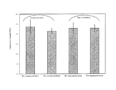
Figure 5 illustrates the dry and wet compressive strengths of a commercial
cement block and the slag-bonded block. The dry compressive strengths of the
commercial
and slag-bonded blocks were 23.6 MPa and 22.8 MPa, respectively. The
compressive
strength of the slag-bonded block satisfied the minimum requirements for the
load-bearing
masonry units as suggested by BS 6073 (2008). The compressive strength of the
wet
commercial cement block dropped by 10% while the wet slag-bonded block
exhibited no
reduction in strength compared to the dry block. The values of compressive
strength for the
slag-bonded block suggest that the block made solely from waste materials can
compete
with the commercial cement block on mechanical performance. No report has
previously
been published on the properties of blocks made with slag as binder and slag
sand as
aggregate. However, the results of the study performed by Monkman and Shao
(2010)
showed that the compressive strength of masonry units made with cement and
slag sand
after being subjected to 2 hours carbonation followed by 28 days hydration was
15.5 MPa.
The higher carbonation period in the current experimental program resulted in
a higher
compressive strength than seen by Monkman and Shao, although they used cement
as
binder.
- 28 -
CA 02942401 2016-09-12
WO 2015/139121 PCT/CA2015/000176
[0195] Figure 6 are pictures of slag bonded blocks, in accordance with
an exemplary
embodiment, and commercial cement blocks after 20 cycles of freeze and thaw.
The two
bottom photos are photos of the commercial cement blocks and the two top
photos are
photos of the slag-bonded block.
[0196] Figure 7 shows the mass loss of slag-bonded and commercial cement
blocks
subjected to 20 freeze and thaw cycles. The commercial and slag-bonded blocks
started
losing mass after 2 and 7 cycles, respectively. Beyond the 7th cycle, both
blocks
experienced the same rate of mass loss. After 20 cycles of freeze and thaw,
the
commercial block lost 32% of its mass, whereas the weight of the slag-bonded
block
decreased by only 17%. Accordingly, the slag-bonded block exhibited higher
resistance
when exposed to freeze and thaw cycles compared to the commercial block.
Considering
the compressive strength and freeze and thaw results, one can conclude that
the
mechanical and durability properties of blocks made with waste materials in
this experiment
were equivalent or superior when compared to a commercial cement block.
Sample building product 2: Slaq wallboard
[0197] The KOBM slag was used as a binder in making slag-bonded
wallboard.
Klockner Oxygen Blown Maxhutte (KOBM) process is considered as a subset of the
basic
oxygen furnace (BOF) process. Its chemical composition, as determined by X-ray
fluorescence spectrometry (XRF), is presented in the aforementioned Table 1.
Prior to its
use, the slag was ground to a powder using a Bico Braun Model 395-5 ball mill
for 2 hours,
and only the material that passed through a 75-pm sieve was used in the
subsequent
experiments. The Blaine fineness of the ground slag was 402 55 m2/kg. The
softwood
sawdust used in making the wallboards was sieved through a 600-pm sieve and
oven-dried
at 50 C until its mass became invariant.
[0198] The carbonation setup shown in Figure 2 and described
hereinabove is also
used herein for the carbonation of wallboards.
[0199] A mixture of KOBM steel slag, sawdust and water was press-
formed at a
pressure of 12 MPa for 15 seconds to create a lightweight steel-slag board
measuring 76
mm by 127 mm, with a thickness of 12 mm. In preliminary tests, the sawdust-to-
slag ratio
- 29 -
CA 02942401 2016-09-12
WO 2015/139121 PCT/CA2015/000176
was varied from 5 to 15% by mass at a water-to-slag ratio of 0.15, and
carbonation carried
out for 2 hours. In subsequent experiments, a sawdust-to-slag ratio of 10% and
a
carbonation period of 24 hours were chosen to optimize the density and
strength of the
board. Mechanical tests on the laboratory wallboards were performed after 28
days of post-
carbonation hydration. Flexural strength and modulus were determined using 3-
point
bending over a 102 mm span. Compressive strength was determined over a
compression
area of 127 mm x 12 mm. The mechanical properties of the slag-bonded sawdust
boards
were compared to those of three commercial wallboards: cement mesh board,
cement-fiber
board, and cement bead board with expanded polystyrene (EPS) beads.
[0200] The capillary water absorption capacity of the KOBM steel slag
sawdust
boards was also evaluated. After 28 days of curing in a sealed bag, the boards
were dried
in an oven at 50 C. After drying, each slag-sawdust board was immersed
vertically in a 5-
mm thick layer of water for 28 days. At 24-hour intervals, the boards were
removed from
the water, their surface dried, and then the boards were weighed. After 28
days, the boards
were removed from the water, their surface dried again, and they were then
tested for
flexural strength, compressive strength, and Young's modulus. The results were
then
compared with those of the dry controls which had been left in a sealed
plastic bag for 56
days.
[0201] To investigate the effect of sawdust on the board performance
of carbonated
slag, the mechanical properties of four batches with different sawdust-to-slag
ratios were
compared. The cylinder compacts were 20 mm in height and 15 mm in diameter and
formed under optimal process conditions: compaction pressure = 12 MPa, water-
to-slag
ratio = 0.15, carbonation time = 2 hours, and CO2 gas pressure = 1.5 bar. A
higher than
optimal water-to-slag ratio was used to incorporate the use of the dry
sawdust.
.. Compressive tests were carried out one hour after carbonation. The effect
of sawdust on
carbon uptake and compressive strength is displayed in Figure 8. Whereas the
carbon
uptake was not significantly influenced by the addition of the sawdust, the
compressive
strength of the carbonated slag decreased sharply with the relative sawdust
content. This
reduction not only resulted from a reduction in the amount of binder, but also
from the
delayed hydration due to the lignin in sawdust. The sugar content in lignin
served as a
- 30 -
CA 02942401 2016-09-12
WO 2015/139121 PCT/CA2015/000176
hydration retarder. Irrespective of the sawdust content, carbonation always
improved the
performance of the slag-bonded sawdust product.
[0202] A picture of a slag-bonded sawdust board specimen (76 x 127 x
12 mm)
made in the laboratory is shown in Figure 9. Such slag-bonded sawdust boards
were tested
28 days after carbonation and hydration. Results for the compressive strength,
the flexural
strength, the modulus of elasticity and the density are presented in Table 5
hereinbelow,
along with those of three commercial board products. They revealed that the
physical
properties of the KOBM slag board were comparable to those of the commercial
products.
The flexural strength of the KOBM slag-sawdust board (6.3 MPa) was higher than
that of
the cement-mesh board and close to those of the cement-fiber board and cement-
EPS
board. The compressive strength of KOBM slag-sawdust board was 13.8 MPa, well
within
the range of strength values of commercial products. Given the high density of
the binder,
the KOBM slag-sawdust board had the highest density (1.4 g/cm3) of the four
materials
tested.
Table 5: Comparison of wallboard properties
Wallboard
Compressive strength (MPa) Flexural strength Modulus Density
(MPa) (GPa) (g/cm
Slag-sawdust-(10%) 13.8 0.6 6.3 0.3 1.1
0.1 1.4 0.04
' Commercial board 13.0 0.5 4.9 0.7 1.9 0.2 1.3
0.01
[Cement-mesh]
Commercial board 14.8 0.6 6.9 0.2 2.2 0.3 1.2
0.06
[Fiber-cement]
Commercial board 15.5 0.7 7.9 0.4 2.2 0.1 1.1
0.04
[Cement-EPS]
[0203] Like cement-based boards, the KOBM-slag board was designed for
wet
applications. Therefore, capillary water absorption and its effect on the
mechanical
performance is an important measure of its durability. The capillary water
absorption of the
slag-sawdust board was measured over a period of 4 weeks. After oven drying at
50 C to a
constant mass, the carbonated slag board was immersed vertically in a 5 mm
deep layer of
water for 28 days. The tests were carried out in triplicate and averaged. The
water
absorption curve is shown in Figure 10. The increase in mass due to water
absorption was
highest in the first 3 days, with the absorption reaching 9.8% by day number
3. The
absorption continued until a plateau was reached by day 19 at around 14.2%,
indicating
that the sample reached saturation through capillary action. The absorption of
water was
- 31 -
CA 02942401 2016-09-12
WO 2015/139121 PCT/CA2015/000176
attributed to the open structure of the board in the presence of sawdust
particles, which
increased the amount of air voids in the sample. The effect of water
absorption on the
mechanical properties of the KOBM slag-bonded sawdust board is presented in
Figure 11.
The flexural strength and elastic modulus of the wet and dry samples were
statistically
similar, indicating that saturation of the pores had no effect on the bending
strength or the
stiffness of the slag board. Nevertheless, there was reduction in compressive
strength after
28 days of water wicking, as the strength dropped from 13.8 MPa to 11.9 MPa, a
14%
decrease.
Example 3: Treatment of steel slag for making a building material
[0204] Two ladle slags (L2 and L3) were received from a steel mill in
Montreal,
Canada. They were collected from the same production line of the steel mill at
different
times. They were received about two years apart from each other. Because of
the slow
cooling, ladle slag was produced as powder which was then packed into porous
"cakes" for
shipping and handling. The as-received dry ladle slag "cakes" were first
crushed and then
further pulverized into powder with Blaine numbers of 318 m2/kg and 247 m2/kg
for L2 and
L3, respectively. L2 slag was received two years earlier than L3.
[0205] The chemical compositions of as-received ladle slag (L2 and L3)
were
determined by the X-Ray Fluorescence (XRF) analysis and are presented in Table
6. The
variability between the two raw forms of slag may be seen. The difference in
composition of
ladle slag is possibly caused by the changes in process and the different
steel products. As
shown in Table 6, ladle slag L2 demonstrates a higher calcium and silica
content, while
ladle slag L3 had higher alumina, iron and magnesium content. The carbon
dioxide content
was determined by infrared based carbon analyzer. They were relatively low.
The free lime
was measured using the Franke method, in accordance with ASTM C114 (2014).
Ladle
slag L3 contains higher free lime than ladle slag L2. To evaluate hydration
and carbonation
behaviour of ladle slag, it is important to determine the mineralogical
phases, mainly the
dicalcium silicate (C2S) and tricalcium silicate (C3S). This was accomplished
by using semi-
quantitative X-ray diffraction (QXRD) analysis with 10% TiO2 as internal
reference (Chung
1974). By comparing the XRD peaks of pure C2S, pure C3S, pure TiO2 and ladle
slag, the
percent of C2S and C3S in ladle slag can be estimated. Ladle slag L2 has much
higher C3S
- 32 -
CA 02942401 2016-09-12
WO 2015/139121 PCT/CA2015/000176
content than ladle slag L3. It is possible for ladle slag to contain C3S
(Posch et al. 2002)
since the process temperature could go over 1500 C (He et at. 2012). Table 6
also shows
the chemical composition of ground waste glass as silica additive for heat
treatment in case
the as-received ladle slag cannot be activated directly by carbonation
(possibly due to the
lack of calcium silicates). The waste glass is the by-product of the recycling
process of
fluorescent lamps and is ground to a powder having a Blaine number of 600
m2/kg.
Table 6: Chemical compisitions and calcium silicate phases of raw material
Chemical compositions (%) Phases (%)
ID CaO SiO2 A1203 Fe2O3 MgO Na2O CO2 Free lime C2S C3S
Ladle slag (L2) 65.23 12.35 16.55 0.79 3.96 0.08 1.10 7.2 9.5
31.1
Ladle slag (L3) 57.55 6.21 23.17 3.55 5.04 0.16 0.20 I
10.8 9.3 3.6
Waste glass 4.89 70.68 1.62 0.22 3.08 16.06 -
[0206]
For each ladle slag, a total of nine slab specimens of 76x127x12 mm were
.. compact-formed at a pressure of 12.5 MPa with a water-to-slag ratio of 0.1.
Six specimens
were subjected to carbonation activation right after specimen formation. Of
the six
carbonated slabs, three were tested immediately after carbonation for
compressive
strength and the other three were tested after subsequent hydration for 35
days in sealed
plastic bags. Three hydration reference specimens were cured in sealed plastic
bags and
tested after 35 days of hydration. The carbonation set-up is shown in Figure
2. A CO2 gas
with a purity of 99.5% was used for carbonation. The gas was first warmed up
by a heater
and then injected into the chamber to a pressure of 0.15 MPa for a duration of
24 hours.
The pressure was maintained constant by the regulator so that the carbon
dioxide
consumed by slag products can be replenished.
[0207] Both ladle slags L2 and L3 were tested first in as-received form.
Ladle slag L2
compacts were CO2- reactive and could develop strength in 24 h by carbon
activation.
However the ladle slag L3 compacts were totally cracked due to the extreme
heat
generated from carbonation.
[0208]
Carbonation behavior of the as-received ladle slag, L2 and L3, was
characterized by carbon dioxide uptake. Ladle slag L2 compacts exhibited
excellent carbon
reactivity. Results from the mass gain method yielded an uptake of 9.9%, which
was
slightly lower than the value of 12.8% obtained by the mass curve method. The
average
- 33 -
CA 02942401 2016-09-12
WO 2015/139121 PCT/CA2015/000176
carbon content by CO2 analyzer was 9.4%, which was in the same order of
magnitude as
measured by the mass gain and mass curve methods. The typical mass curve of
ladle slag
L2 compact is shown in Figure 12. It was interesting to notice that more than
70%
carbonation reaction had occurred in the first two hours. It seems that the
ladle slag
compact could reach a similar degree of carbonation reaction as ladle slag
powder.
[0209] By contrast, ladle slag L3 with low silica content cracked
during the
carbonation, as shown in Figure 13. There was no mass increase and no carbon
dioxide
uptake. Instead, significant heat was generated. The ladle slag L3 compacts
cracked in a
similar way as the quick lime (CaO) compact, indicating that the heat was
created by
carbonation of free lime. This heat dissipation was felt immediately after the
L3 slag was
mixed with water, an effect arising from the hydraulic reaction of free lime.
As seen in Table
6, the free lime content of L3 was 50% higher than L2. It is likely there is a
threshold value
of free lime content over which ladle slag cannot stand the hydration and
carbonation
reactions.
[0210] Table 7 shows compressive strength of ladle slag compacts due to
hydration
and carbonation. Ladle slag L2 was weak in the hydraulic reaction. The
compressive
strength of L2 compacts reached only 6.0 MPa after 35 days in sealed
hydration. On the
other hand, the same compact specimens that underwent 24 hours of carbonation
curing
achieved a significantly higher compressive strength of 34.8 MPa. The compact
specimens
that underwent combined curing of 24 h carbonation followed by 35 day
hydration achieved
a compressive strength of 39.5 MPa, demonstrating that the ultimate strength
was the
superposition of early carbonation strength with subsequent hydration
strength. In other
words, carbonation did not hinder hydration, and more strength was gained
after
carbonation from the subsequent hydration. For ladle slag L3, the compacts
were cracked
either by carbonation or by hydration. In hydration of ladle slag L3, a
similar crack pattern
as shown in Figure 13 was developed in the hydrated compact after 10 days in
sealed
hydration. It is the free lime content that produced the heat and cracked the
compacts.
Table 7: Compressive strength of ladle slag_compacts
ID Type Hydration Carbonation Subsequent Test age
Compressive
of time (days) time (h) hydration
(days) (days) strength (MPa)
slag
L2-0C+35H L2 35 35 6.0 1.7
L2-24C+OH L2 0 24 0 1 34.8 9.52
- 34 -
CA 02942401 2016-09-12
WO 2015/139121 PCT/CA2015/000176
L2-24C+35H L2 0 24 35 36 39.5 11.9
L3-0C+35H* L3 - 35 0 0 35 0
L3-24C+OH* I L3 0 24 0 1
[0211]
Figure 14 shows the XRD patterns of both as-received slags, L2 and L3. The
L2 slag with higher Ca and Si content clearly exhibited strong peaks for
C2S/C3S, calcium
hydroxide (CH), and much less free lime content. In L2 slag, the major phases
included
C2S/C3S phases, mayenite (C12A7) and minor phases included merwinite (C3MS2)
and
gehlenite (C2AS). Calcium-ferrite (C2F) and MgO were found in trace amounts.
The L3 slag,
on the other hand, revealed the presence of major phases of CH, mayenite
(C12A7),
merwinite (C3MS2), free lime (free-CaO) and minor phases of gehlenite (C2AS),
C2S/C3S,
and calcium-ferrite (C2F). TG and DIG curves of L2 and L3 are presented in
Figure 15. The
occurrence of mass loss between 400-500 C confirmed the presence of CH in L2
and L3.
Mineralogical phases explained why ladle slag L2 was reactive with CO2
producing
strength-contribution reaction products and why ladle slag L3 was cracked. It
seems that
calcium silicate phases played a critical role in strength development. While
the C2S
content for both slag samples was virtually identical, the contents for C3S
varied
significantly (Table 6). A C3S content of 31.1% in L2 slag was 9 times higher
than the value
obtained for L3 slag, where C3S content was seen to be 3.6%. Although ladle
slag
generally exhibits higher C2S content compared to C3S, ladle slag with high
C3S content,
like that disclosed herein for the L2 sample, has been previously reported. It
is well
established that the mineralogical phases of slag are strongly controlled by
the temperature
in which the slag is produced. The temperature of molten ladle slag was
estimated to be
about 1500 C (He et al. 2012); the higher the processing temperature of
molten steel slag,
the greater the chance to form C3S. Posch et al. (Posch et al. 2002) showed
that their ladle
slag with a basicity of 2.1 had C2S and C3S contents of 9.6% and 24.7%,
respectively. L2
slag with high C3S content displayed promising results pertaining to CO2
reactivity and
strength gain by carbonation.
[0212]
The XRD patterns for ladle slag L2 compacts after 24 h carbonation, after 24
h carbonation followed by 35 day hydration, and after 35 days hydration are
plotted in
Figure 16 together with that of the as-received reference slag powder.
Comparing the as-
received and carbonated slags, it was clear that carbonation resulted in the
precipitation of
- 35 -
CA 02942401 2016-09-12
WO 2015/139121 PCT/CA2015/000176
CaCO3 phases, and the simultaneous consumption of the calcium silicate phases
and
Ca(OH)2 to form carbonation products. Moreover, XRD results suggest that
merwinite was
not reactive with CO2. Meanwhile, the slight reduction of intensity for the
mayenite peaks
may indicate the weak reactivity of mayenite with CO2. The reduction of
intensity at 26 of
18 after carbonation was likely due to the consumption of both calcium
hydroxide and
mayenite. It seems that calcium oxide minerals bonded structurally with
elemental
components (Mg, Fe or Al), other than silica, displayed low CO2 reactivity in
comparison
with calcium silicate phases.
[0213] The reaction products can be determined by TG/DTG analysis.
Typical TG
and DTG curves for compacts made with L2 slag are plotted in Figure 17. Based
on the
DTG peaks, the mass loss can be divided into three regions which were
representative of
three typical reaction products: 105-400 C, 400-500 C and 500-900 C. Mass loss
between
105-400 C represented water loss due to dehydration of C-S-H and C-A-H, mass
loss
between 400-500 C represented water loss due to dehydration of Ca(OH)2 and
mass loss
between 500-900 C represented CO2 loss due to decarbonation of CaCO3. The
assumption that mass loss between 105-400 C was due to dehydration of C-S-H
and C-A-
H was based on the fact that both calcium silicate and mayenite can be
hydrated,
generating hydration products. The reaction products are summarized in Table
8.
Comparing the hydrated samples to the carbonated samples, the calcium
hydroxide
content in the carbonated slag was reduced while the calcium carbonate was
significantly
increased. The formation of C-S-HiC-A-H and CH in the hydrated slag was
indicative of
slow hydraulic behavior. Although the C-S-H+C-A-H content was similar in the
hydrated
and carbonated slag compacts, the carbonated slag displayed much higher
compressive
strength. This improved strength is believed to be attributed to the calcium
carbonate
formation. The total content of C-S-HiC-A-H plus CaCO3, considered the dual
phases
contributing to strength gain, was higher in the carbonated slag than in the
hydrated one.
The 35-day compressive strength was 6 times greater in the carbonated sample
than in the
hydrated sample. The precipitated calcium carbonate crystals fortify the slag
binder in a
manner synonymous to a form of particulate-reinforced composite, resulting in
a stronger
matrix. The peak at the angle of 18 in the XRD pattern shown in Figure 4-6
was a mix of
calcium hydroxide and mayenite. While carbonation apparently consumed both
calcium
- 36 -
CA 02942401 2016-09-12
WO 2015/139121 PCT/CA2015/000176
hydroxide and mayenite, the reactivity of mayenite with CO2 is weaker. Slow
hydration of
mayenite could make a contribution to the formation of calcium-aluminate-
hydrate (C-A-H).
Table 8: Reaction products in ladle slag (L2) binder
ID Age Water loss in Water loss in CO2 loss in
Ca(OH)21) CaC032 1
(days) CSH+CAHa CHb CaCO3b
L2 as-received, % - 0.31 1.93 1.00 7.93 2.27
L2-0C+35H, % 35 3.31 2.82 1.06 11.59 2.41
L2-24C+OH, % 1 3.50 0.57 7.91 2.34 17.98
_
L2-24C+35H, to 36 3.00 0.61 ______ 7.18 2.51 16.32
Calculated based on mass loss between 105-400 C
b Calculated based on mass loss between 400-500 C
Calculated based on mass loss between 500-900 C
[0214] To improve the carbonation behavior of ladle slag L3, heat
treatment was
performed. The glass powder was mixed with slag powder in a pulverising
machine for 30
seconds. The mixed powder was then compacted in a steel mold under 50 MPa
pressure
to form prism pellets of 20x20x14 mm. The prism pellet compacts were then
placed on
refractory trays and carefully positioned inside the furnace. The heat
treatment temperature
was set at 1100 C to minimize the energy consumption and maximize the
formation of
dicalcium silicates. It took about 3.5 hours for the furnace to reach 1100 C
at a rate of 5
C/min. The pellets were held at 1100 C for 30 minutes and then removed from
the
furnace immediately for cooling in open air at ambient conditions at a cooling
rate of 600 C
per hour with the help of a cooling fan. It took about 2 hours to cool the
pellets down to
ambient temperature. The pellet compacts were then ground to a powder by using
a
pulveriser to a Blaine number of 286 kg2/m. The resulting treated ladle slag
is referred to
herein as L3T (T denoting "treated"). The treated slag powder was then used to
make nine
slab samples similar to the ones used in the L2 and L3 tests. Six were
carbonated for 24
hours. Of the six, three were tested immediately after carbonation for
compressive strength
and three were tested after subsequent hydration of 35 days. Additionally,
three were
tested as a hydration reference after being sealed in a plastic bag for 35
days. The
chemical composition of the treated ladle slag (L3T) is presented in Table 9.
The addition of
waste glass increased the SiO2 content from 6.2 to 17.0%, more than double the
original
content. This addition was administered for the purpose of increasing the high
temperature
reaction between free-lime and silica for the eventual formation of calcium-
silicates. As
shown in Table 9, the free lime content dropped to 0.15% from 10.8%,
confirming that the
devised heat treatment was effective in beneficially combining free lime and
silica to
- 37 -
CA 02942401 2016-09-12
WO 2015/139121 PCT/CA2015/000176
produce more dicalcium silicates. With the aid of semi-quantitative XRD
analysis, the
fractions of the calcium silicate phases in the sample were determined.
Compared to the
untreated L3 slag material, the C2S content was increased from 9.3% to 20.3%.
As
expected, there was no change in the quantity of the C3S component, since the
temperature employed was not sufficient enough to promote the formation of
this phase.
Figure 18 shows the location of the normalized compositions of L3 and L3T on
the primary
crystalline phase diagram of the CaO-Al2O3-SiO2. The supplementing of silica
moved the
original makeup of the ladle slag from a highly saturated lime region to a C2S-
dominant
one, having a characteristically lower basicity value (2.74 compared to the
original 9.27).
Thermodynamically, this favoured the crystallization of C2S within the
modified slag, thus
contributing to a noticeable increase in CO2 reactivity.
Table 9: Chemical composition and calcium silicate phases of treated ladle
slag
Chemical compositions (Y.) j Phases (%)
ID CaO Ji102 A1203 Fe2O3 MgO Na2O CO2 Free C2S CS
lime
L3T 46.60 I 17.00 20.70 5.39 4.58 0.60 0.01 0.15
20.3 3.0
[0215]
Carbonation behavior of treated ladle slag L3T was characterized by CO2
uptake from the carbonation reaction. The 127x76x12 mm compacts were subjected
to 24
h carbonation curing at a gas pressure of 0.15 MPa. CO2 uptakes recorded by
the three
different methods were of similar values: 5.3% by mass gain method, 4.0% by
mass curve
method, and 5.1% by infrared-based CO2 analyzer. A typical mass curve is
presented in
Figure 12. The absolute uptake was lower in L31 than L2. Similar to L2, most
of the
reaction of L3T occurred in the first two hours. It was apparent that heat
treatment made
the ladle slag L3 CO2-reactive, although the degree of reactivity was only
half of that of L2.
This was mainly attributed to the relatively higher calcium silicate content
(02S+C3S=
40.6%) in L2 slag compared to 23.3% in the modified L3T slag.
[0216]
Compressive strength of the modified L3T compacts was evaluated. Results
are summarized in Table 10. Hydrated-only specimens exhibited low hydraulic
properties,
where hydration to 35 days translated to a strength gain of 3.8 MPa. This was
only half of
the strength developed in L2 slag, possibly due to the low C3S content of the
treated slag.
There was no hydration-generated cracking, further confirming the conversion
of free lime
- 38 -
CA 02942401 2016-09-12
WO 2015/139121 PCT/CA2015/000176
into calcium silicates. Carbonation curing for 24 hours increased the
compressive strength
of the treated slag to 25.9 MPa. Undergoing a combined 24 hour carbonation
plus 35 day
hydration curing raised the strength to 26.7 MPa. Therefore, it appears that
the subsequent
hydration after carbonation was insignificant. While demonstrating a
significant
improvement, the modified L3T slag could not achieve as high a compressive
strength as
that recorded for the L2 slag sample. Likely this could be owing to a lower
calcium silicate
content in the L3T slag and a lower carbonation reactivity.
Table 10: Compressive strength of treated ladle slag compacts
ID Type Carbonation CO2 Subsequent Test age
Compressive
of time (h) pressure hydration (days)
strength (MPa)
slag (MPa) __ jc1)
L3T-0C+35H L3T 0 35 35 3.8 0.9
L3T-24C+OH L3T 24 0.15 0 1 25.9 4.9
3L31-24C+351-1 L3T 24 0.15 35 36 26.7 3.3
[0217] Figure 19 shows the XRD patterns for L3T slag after heat treatment,
after 24
h carbonation, after 24 h carbonation followed by 35 days hydration and after
35 days
hydration. Mayenite and calcium silicates were the major phases identified in
the treated
slag. Calcium hydroxide was totally eliminated by heat treatment. This was
evidenced by
the TG curves in Figure 20. The treated slag also displayed the presence of
merwinite, as
well as traces of gehlenite and calcium iron oxide. The contents of the
calcium silicate
phases were estimated using semi-quantitative analysis, and the results are
shown in
Table 9. The intensity of peaks for mayenite decreased after 35 days
hydration, suggesting
the formation of calcium aluminate hydrate. Mayenite can be hydrated in the
presence of
water (Segui et al. 2013). A slight reduction of mayenite intensity after
carbonation
suggests the reactivity of mayenite with 002. This phenomenon was also
observed for L2.
Additionally, gehlenite was non-reactive, as its peak showed no change during
carbonation
or hydration curing. The presence of the calcium carbonate peak at 20 angle of
29
demonstrates the carbonation reaction of calcium silicate phases.
[0218] The TG/ DTG curves for the treated slag (L3T) subjected to
different curing
conditions are presented in Figure 20, and the quantitative results are
summarized in Table
11. The TG/DTG curves for treated slag were flat, confirming the elimination
of calcium
hydroxide during the treatment. The water loss between 105-400 C,
representing the C-S-
- 39 -
CA 02942401 2016-09-12
WO 2015/139121 PCT/CA2015/000176
H+C-A-H content of the sample, tested immediately after carbonation showed an
increase.
Carbonation activation also increased the calcium carbonate content, as
expected. The
presence of more calcium carbonate particles within the hydrated phases (C-S-H
and C-A-
H) helped fortify the resulting composite structure. The extent of strength
gain can therefore
be gauged by the amount of CaCO3 precipitation. The co-existence of calcium
carbonates
with the hydrated phases can considerably strengthen this composite matrix
system.
Table 11: Reaction products in treated ladle slag (L3T) binder
ID Age Water loss in Water loss in CO2 loss in
Ca(OH)2b CaCO3b
________________ (days) CSH+CAHa __ CHb CaCO3b
L3T, % 0.11 0.05 0.02 0.21 0.05
L3T-0C+35H, % 35 1.56 1.00 0.73 4.12 1.65
L3T-24C+OH,% 1 3.49 1.02 3.64 4.19
L3T-24C+35H, % 36 4.04 0.93 5.03 3.82 8.27
11.43
a Calculated based on the mass lost at 105-400 C
b Calculated based on the mass lost at 400-500 C
C Calculated based on the mass lost at 500-900 C
[0219] In this study, the carbonation behavior of two typical ladle
slags was
investigated for their capacities to serve as cementing binder in building
product
applications. They were representative of two groups of slag: one can be
carbonation-
activated in its as-received form and one needs heat treatment with silica
addition. Some
conclusions that can be drawn are:
1. Ladle slag with higher SiO2 content and lower free lime showed stronger
carbonation
reactivity. The as-received slag could be activated by carbon dioxide to
develop sufficient
strength for building product applications. The high carbonation reactivity
was attributed to
the presence of calcium silicate phases. It is recommended that silica be
considered as
deoxidization agent instead of alumina during the production of steel in order
to produce
more calcium silicates in ladle slag and reduce the free lime content, leading
to a more
CO2-reactive slag for value-added applications.
2. Ladle slag with higher aluminate content or higher free lime content could
not be
activated by carbon dioxide to develop strength. Heat treatment at 1100 C
with silica
addition was effective to produce more dicalcium silicate phases and improve
carbonation
reactivity. The heat treatment and addition of silica can be accomplished when
slag is still
in the molten stage to produce value-added ladle slag.
-40 -
CA 02942401 2016-09-12
WO 2015/139121 PCT/CA2015/000176
3. The ultimate strength of the ladle slag activated by carbonation was
attributed to the
hybrid structure of carbonation and hydration products. The calcium carbonate
precipitations fortified the amorphous C-S-H+C-A-H matrix by forming a
particulate
reinforced composite.
4. It was the C2S and C3S phases, not the total CaO content, that determined
the
carbonation reactivity of ladle slag. The calcium-bearing phases such as
merwinite and
gehlenite were not CO2-reactive and did not make contributions to the strength
by carbon
activation.
Example 4: Treatment of Slag with Glass to Make Synthesized Cement
[0220] The ladle slag was the by-product from the steel making process at
Quebec
Rio Tinto Iron & Titanium (RTIT) plant. Because of the slow cooling, ladle
slag was
produced as powder which was then packed into porous "cakes" for shipping and
handling.
The as-received dry ladle slag "cakes" were first crushed and then further
pulverized into
powder with Blaine number of 247 m2/kg.
[0221] Waste glass was collected from the recycling of fluorescent lamps.
They were
crushed and ground to a Blaine number of 600 m2/kg and used as the source of
silica for
synthesizing cement. The chemical composition of ladle slag and waste glass
materials
were determined by XRF, and the results are presented in Table 12. Ladle slag
showed
57% of CaO and waste glass had 70% of SiO2. Free lime content of as-received
ladle slag
is 10.8% which is determined by the Franke method in accordance with ASTM
C114. A
semi-quantitative XRD analysis of the calcium silicate content, i.e. C2S and
C3S, of the
ladle slag was performed to determine the quantity of C2S and C3S in the
original slag. A
2-point calibration method was used to compare the peak heights in the mixture
of ladle
slag and T102(90%slag+10%T102) to those of pure C2S (100% C2S), pure C3S (100%
C3S)
and pure Ti02(100% TiO2) (Chung 1974). The slag contained 9.3% C2S and 3.6%
C3S.
Table 12: Chemical composition and phases of as-received materials
Chemical compositions (%) Phases (%)
CaO SiO2 A1203 Fe203 MgO K20 Na2O Free lime C2S C3S
Ladle slag (L3) 57.55 6.21 23.17 3.55 5.04 0.02 0.16
10,6 9.3 3.6
Waste glass 4.89 70.68 1.62 0.22 3.08 0.48 16.06 -
-41 -
CA 02942401 2016-09-12
WO 2015/139121 PCT/CA2015/000176
[0222] Different batches were prepared where waste glass was added to
the slag at
varied weight percentage and mixed individually in a pulverising machine for
30 seconds.
The mixed power was then compacted into 20x20x20 mm cubic clinkers in a steel
mold
under 50 MPa pressure. The cubic clinkers were seated on refractory plates
that were then
placed in a high temperature furnace. The temperature of the furnace was
increased to the
desired temperature at a rate of 5 C/min. When the desired temperature was
reached, it
was kept constant for 30 minutes, after which the clinkers were extracted and
rapidly
cooled by facing an air draft generated by a mechanical fan for 2 hours. The
cooled cubic
clinkers were then ground to a powder with a Blaine number of 286 m2/kg by
pulverizing for
2 minutes.
[0223] Hydraulic behaviour of synthesized cement and its CO2
reactivity relies
strongly on the chemical composition of the raw materials and the synthesizing
temperature. A comprehensive parametric study was conducted to optimize the
process.
[0224] To determine the optimal glass-to-slag ratio, the mixtures
with 10, 20, and 30
weight percent waste glass were studied. The clinkers with different glass-to-
slag ratios
were then heated up to a constant temperature of 1250 C. The synthesized
cement was
shaped into 20x20x12 mm prism compacts and activated by carbonation for 24
hours at a
gas pressure of 0.15 MPa. The optimal glass-to-slag ratio was chosen based on
the
compressive strength by carbonation.
[0225] To further optimize energy consumption, different synthesizing
temperatures,
all below 1250 C, were tested. Clinkers were prepared using the optimized
glass-to-slag
ratio and synthesized at different temperatures of 700 C, 800 C, 1100 C and
1200 C.
Cement was synthesized from each of the clinkers.
[0226] For performance evaluation of the synthesized cement produced
from the
clinkers heated at the different temperatures, cement prism compacts of
dimensions of
20x20x12 mm were prepared. The thickness of 12 mm was selected to simulate
fiber-
cement board products. For each prism sample, 10 g of synthesized cement was
mixed
with 1 g water (water/cement = 0.1). They were compact-formed under a pressure
of 12.5
MPa. These prism cement pastes were activated by carbonation for 2 hours at
0.15 MPa.
After carbonation, half of the specimens were tested immediately for
compression strength
-42 -
CA 02942401 2016-09-12
WO 2015/139121 PCT/CA2015/000176
and half of the specimens were sealed for subsequent hydration. Combined
curing included
a constant carbonation followed by subsequent hydration for durations of 3,
14, and 35
days. This would help assess the effect of subsequent hydration on the
characteristics of
carbonated cement. Reference samples were also made and sealed in a plastic
container
for hydration of 35 days. To highlight the effectiveness of the proposed
synthesizing
process, prisms prepared from as-received slag were also subjected to the same
carbonation and hydration curing conditions.
[0227] The values of carbon dioxide uptake and compressive strength
recorded for
synthesized cement at different percentage of waste glass are presented in
Table 13.
Addition of 10 to 20% waste glass yields a compressive strength up to 36 MPa
after 24
hours carbonation with a CO2 uptake at about 9.6%. A further increase of waste
glass
content to 30% resulted in a decrease in both strength and carbon dioxide
uptake. For this
reason, the optimal percentage of glass-to-slag ratio was selected as 20%.
This parametric
study was conducted while synthesis was carried out at a fixed temperature of
1250 C.
Table 14 presents CO2 uptake and compressive strength results for cements
prepared
using 20% glass-to-slag ratio and synthesized at different temperatures
ranging from 700 to
1200 C. While temperature increase had no significant effect on carbon
dioxide uptake, it
had a significant effect on compressive strength. The higher the synthesizing
temperature,
the higher the compressive strength. In Table 14, the strength was gained by
carbonation
.. activation of 2 hours. In comparison to 24 hours in Table 13, a shorter
process time was
economically beneficial. The strength gain by 2 h carbonation was comparable
to 24 h
carbonation if the cements were processed at about 1200 C. The choice of
temperature
was to yield the optimized conditions that successfully address practicality,
equivalent
alkalinity, free lime content, strength, energy consumption and environmental
implications.
Taking into consideration these parameters leads to the conclusion that the
synthesizing
temperature of 1100 C with glass-to-slag ratio of 20% resulted in suitable
cement for
carbonation activation with relatively low energy consumption.
Table 13: Results of cement synthesised at different percentage of waste glass
ID WTL1 WTL2 WTL3
Waste glass content ( /0) 10 20 ___ 30
Synthesizing temperature ( C) 1250 j1250 1250
Carbonation time (h) 24 J 24 24
CO2 uptake (%) 9.6 0.7 9.7 0.5 3.1 0.3
- 43 -
CA 02942401 2016-09-12
WO 2015/139121 PCT/CA2015/000176
Compressive strength (MPa) 36.0 19.2 36.7 13.8 13.1 0.4
Table 14: Results of cement synthesized at different temperature
ID WTL4 WTL5 WTL6 WTL7
Waste glass content (1)/0) 20 20 20 20
Synthesizing temperature ( C) 700 800 1100 1200
Carbonation time (h) 2 2 2 2
CO2 uptake (%) 5.8 1.9 8.1 0.0 5.0 0.3 6.6 0.7
Compressive strength (MPa) 15.6 1.1 25.6 1.6 32.7 4.4 34.4 1.3
[0228] Table 15 shows the chemical composition of ladle slag
synthesized with 20
wt % waste glass at 1100 C. The equivalent alkali of synthesized cement was
calculated
as 0.7%; slightly higher than the value of 0.6% suggested by ASTM C150. The
high sodium
oxide content of waste glass made a contribution to the high alkalinity level
of synthesized
cement. Despite the high alkalinity level, the alkali-silicate reaction cannot
be initiated as
carbonation mitigates the potential of reaction. The fineness of synthesized
cement was
measured as 286 m2/kg. Waste glass is high in silica content, and its addition
to ladle slag
increases the overall content of silica, and also reduces the overall
fractions of CaO and
Al2O3 contents in the synthesized cement. This modification shifts the
composition of the
material in the primary crystalline phase diagram of the CaO-Al2O3-SiO2, as
shown in
Figure 18. The intentional shift was effective in reducing the free lime
content from 10.8% in
the as-received slag to 0.15% in synthesized cement, suggesting that free lime
reacted with
the added silica to promote the formation of the desired calcium silicate
phases. As a
result, free lime content was significantly reduced and C2S content increased.
Table 15 Chemical composition of synthesized cement (%)
Chemical compositions ( ./0) Phases (%)
I
CaO S102 A1203 Fe203 MgO K20 Na2O Free lime C2S C3¨
T1100 (L3T) 46.60 ; 17.00 20.70 5.39 4.58 0.20 0.60 0.15 18.2
1.4
[0229] The XRD patterns of as-received slag and the synthesized cement are
illustrated in Figure 21. It can be seen that the as-received slag consisted
primarily of free-
lime and mayenite, a calcium-aluminate phase. Other phases identified were in
trace
amounts, including gehlenite, calcium silicate(s), and calcium hydroxide.
Mayenite
remained as one of the major constituent phases even after the synthesising
process with
glass was completed. Other studies have also related similar findings with
regards to
- 44 -
CA 02942401 2016-09-12
WO 2015/139121 PCT/CA2015/000176
mayenite presence (Uibu et al. 2011). Meanwhile, peak intensities of calcium
hydroxide
and free calcium oxide phases were reduced, suggesting a reaction with the
supplemented
silica to form calcium silicate-based phases. The results of the free lime
content obtained in
accordance with the Franklin method confirmed the above observation. Calcium
silicate
phases (C2S/C3S) are believed to be the main phases that lend cementitious
materials their
hydraulic behaviour and CO2 reactivity (Rostami et al. 2011). The calcium
silicate content of
as-received slag and synthesized cement was quantified through the QXRD
analysis. As
shown in Table 15, the C2S content of slag synthesized with waste glass
increased from
9.2% to 18.3% while the C3S content did not significantly change. An increase
in the C2S
content further confirms the synthesizing process was successful in combining
free lime
with silica in glass to form calcium silicate phases. C3S formation was not
expected, since
reactions associated with this phase require higher temperatures (Taylor
1997). It is
believed that implementing a higher temperature could result in the formation
of C3S,
however, it may not be justifiable from an economic and practical point of
view. For the
purpose of energy conservation, the temperature of 1100 C was adopted for this
study.
[0230] Figure 22 shows the TG/DTG curves of as-received slag and the
synthesized
cement. For as-received slag, a peak in the DTG curve between 450 C and 550
C
suggests the presence of CH as was noticed in the XRD pattern. No mass loss
was
recorded for this synthesized, non-carbonated cement, suggesting that neither
carbonates
nor calcium silicate hydrate phases were present in cement. The existing
calcium hydroxide
in L3 was eliminated during the synthesizing process as it was decomposed at
the
temperature of 500 C.
[0231] The results of compressive strength and carbon dioxide uptake
of pastes
prepared from as-received ladle slag and synthesized cement, subject to
various curing
regimes, are presented in Table 16. The results of the synthesized cement are
also shown
in Table 16. The synthesis process made non-hydraulic material show hydration
behaviour.
The compressive strength of 35 days of hydrated cement paste (T1100-1) had
exhibited a
measurable strength gain of 9.1 MPa after 35 days hydration alone. This was
indicative of
the formation of calcium silicates during the synthesis process. When exposed
to
carbonation curing, the cement displayed rapid strength gain. The compressive
strength of
cement pastes increased immediately after 2 hours of carbonation, reaching
23.1 MPa. As
-45 -
CA 02942401 2016-09-12
WO 2015/139121 PCT/CA2015/000176
shown in Figure 23, subsequent hydration of carbonated cements made further
contributions to strength gain. The compressive strength of carbonated cement
pastes after
3, 14 and 35 days of subsequent hydration achieved 37.3, 43.6 and 45.7 MPa,
respectively. Carbonation seemed to intensify the hydraulic properties of the
synthesized
cement. It is believed this phenomenon occurred as more mayenite was
accessible for
hydration after the bonded C2S was consumed over the carbonation period.
Samples
carbonated for 2 hours and followed by 35 days hydration (T1100-5) showed a
peak at 247
C in the DTG curve (Figure 24) suggesting the formation of calcium aluminate
hydration;
this peak cannot be observed in the hydrated sample (T1100-1). As presented in
Table 16,
the CO2 uptake of carbonated cements determined based on the mass gain method
after 2
hours carbonation was less than 5%. Despite the low carbon dioxide uptake, the
strength
gain was quite significant. It is believed that the precipitated calcium
carbonate crystals
fortify the hydration products in a manner synonymous to a form of particulate
composite.
The dispersion of the relatively more resilient carbonates within the C-S-H+C-
A-H phase
enhanced the composite's microstructure and lent the composite paste better
mechanical
properties. As an analogy, one may compare the C-S-H/C-A-H-CC system with the
cement
paste-aggregate or concrete-fiber systems where the dispersed aggregate or
fiber in the
cement paste or concrete make a composite system with a high strength.
Table 16 Carbonation and hydration of synthesized cement pastes
ID Type of Carbonation Hydration (days) CO2 uptake
Compressive
slag (h) (%) strength (MPa)
¨L3-24C+OH As-received 24 0 __________________________ Cracked
L3-0C+35H As-received 0 35 Cracked
T1100-1 Treated 0 35 9.1 0.5
T1100-2 Treated 2 0 4.0 0.2 23.1 2.9
_T1100-3 Treated 2 3 4.7 0.3 37.3 4.4
T1100-4 Treated 2 14 4.8 0.2 43.6 6.4
T1100-5 Treated 2 35 4.8 0.1 45.7 4.0
24C=24 hours of carbonation
OC=No carbonation
35H=35 days of hydration
OH=No hydration
[0232] Figure 24 illustrates the TG and DTG curves of carbonated/hydrated
samples
made with the synthesized cement. The mass loss experienced above 550 C was
considered for calculating the CO2 uptake. As presented in Table 17, the
values of CO2
uptake after 2 hour carbonation (T1100-2) obtained from the TG curves were in
the same
-46 -
CA 02942401 2016-09-12
WO 2015/139121 PCT/CA2015/000176
order of magnitude as those determined by the mass gain method in Table 15. As
expected, no mass loss was observed for the hydrated sample (T1100-1) after
550 C,
indicating the absence of carbonate. The water loss of calcium silicate
hydrate and calcium
aluminate hydrate of cured cements was measured based on mass loss between 105
C
and 450 C, and showed an increase with an increase in the hydration time. The
DTG
curves of carbonated cements that were subsequently hydrated for 3, 14 and 35
days
constantly showed an increase in intensity of the peaks in Figure 24 with
respect to the
carbonation without hydration (T1100-2). This increased mass loss experienced
by
cements subject to subsequent hydration was indicative of the increase in C-S-
H+C-A-H
formation due to hydration. The other evidence of hydration was seen by the
increase in
Ca(OH)2 in carbonated cements. Relatively hydrated cement had shown the lowest
Ca(OH)2 which explained the low hydration strength after 35 days of hydration.
Although
the increase in C-S-H+C-A-H content in subsequent hydration was not
proportional to the
curing time, the cement after 2 h carbonation and 35 days hydration was much
stronger
than the cement after 35 days hydration ( 45.7 MPa versus 9.1 MPa), suggesting
the
composite action by the simultaneous formation of C-S-H+C-A-H and CaCO3
phases. It
was obvious that carbonation had promoted subsequent hydration which was
possibly
attributed to the calcium carbonates produced by carbonation. The carbonates
may act as
calcite seeds for subsequent hydration.
Table 17: Reaction products of carbonated and hydrated synthesized cement
pastes
Sample Age Water loss of Water loss of CO2 loss Ca(OH)2
CaCO3 content
___________ (days) CAH+CSH CH (0/0) (%)* (%)**
T1100-1 35 3.30 0.15 0.5 0.62 1.02
T1100-2 2 2.76 1.13 2.7 4.65 6.11
hours
11100-3 3 3.42 1.24 3.6 5.10 8.14
T1100-4 14 3.64 1.30 3.8 5.34 8.66
T1100-5 35 3.76 1.17 4.0 4.81 9.16
* Calculated based on the mass lost at 450-550 C
Calculated based on the mass lost at 550-850 C
[0233] Figure 25 shows the XRD patterns of synthesized cement that had
experienced different curing regimes. It is noticeable that peaks of calcium
carbonate
appeared in the carbonated cements, as precipitation of this phase occurred
from the
reaction of CO2 with the calcium silicate phases. By comparing the patterns of
non-
carbonated and carbonated samples, one may conclude that gehlenite did not
react with
-47 -
CA 02942401 2016-09-12
WO 2015/139121 PCT/CA2015/000176
CO2 and did not contribute to strength gain. Meanwhile, a slight reduction in
mayenite
peaks indicates its potential reactivity with CO2. The XRD patterns of
hydrated and
carbonated synthesized cement also revealed a slight reduction in mayenite
intensity over
the period of 35 days hydration, suggesting the hydration of mayenite which
resulted in
formation of C-A-H.
[0234] The results of this study show that waste glass can be used as
source of
silica to promote the formation of calcium silicate phases, enhance
carbonation reactivity
and induce considerable hydration strength gain.
[0235] The synthesized cement displayed strength development when
subject to
carbonation, hydration, or a combination of both. The best practice with this
special cement
is carbonation first for early strength and hydration second for late
strength. The
combination of 80% of ladle slag fines with 20% waste glass synthesized at
1100 C
resulted in a stable cement capable of gaining strength when subjected to
carbonation and
hydration curing. Using waste glass as the additive could convert a non-
reactive ladle slag
into a value-added binder product. The results also suggested that carbonation
curing
promoted the strength gain associated with subsequent hydration. The composite
action
generated by calcium carbonate in a C-S-H-C-A-H matrix eventually played an
important
role in gaining strength.
Example 5: Treatment of Slaq with Fly Ash to Make Synthesized Cement
[0236] The ladle slag is the same as used with the glass of example 4. The
as-
received dry ladle slag "cakes" were first crushed and then further pulverized
into powder
with a Blaine number of 247 m2/kg. Type F fly ash with a Blaine number of 438
m2/kg
sourced from Alberta, Canada was introduced to ladle slag as a source of
silica oxide. The
chemical composition of ladle slag and fly ash materials were all obtained by
XRF, and the
results are presented in Table 18. Ladle slag has shown 57% of Ca0 and fly ash
has 54%
of Si02.
Table 18: Chemical composition of raw materials and produced cement
Chemical composition (%) Phases (%)
CaO SiO2 A1203 Fe2O3 MgO K20 Na2O Na209 Free C2S C3S
lime
LLadle slag (L3) 57.55 6.21 23.17 3.55 5.04 0.02 0.16 0.17
10.8 9.3 3.6
Fly ash 11.3 54.39 23.65 3.9 1.17 0.75 2.91
3.42 -
-48 -
CA 02942401 2016-09-12
WO 2015/139121 PCT/CA2015/000176
Treated ladle 42.99 16.92 25.26 6.51 4.22 0.03 0.22 0.24
0.11 13.5 1.9 ¨
slag (F1250)
*Na20e=Na20+0.658 xK20
[0237] Cement was synthesized according to the following steps. Fly
ash was added
to the slag at variable weight percentages and mixed individually in a
pulverising machine
for 30 seconds. The mixed power was then compacted in a 20x20x20 mm steel mold
under
50 MPa pressure. The pellets were seated on refractory plates that were then
placed in a
high temperature furnace. The temperature of furnace was then increased to the
desired
temperature at a rate of 5 C/min. When the desired temperature was reached,
the furnace
was maintained at that temperature for 30 minutes. After heating, the
compacted samples
were removed from the furnace immediately for cooling in open air at ambient
conditions at
.. the cooling rate of 600 C per hour with the help of a cooling fan. The
cooled cubic clinkers
were then ground to a powder with a Blaine number of 202 m2/kg by pulverizing
for 2
minutes.
[0238] Hydraulic behaviour of synthesized cement and its CO2
reactivity relies
strongly on the chemical composition of the raw materials and the synthesizing
temperature. For this reason, a comprehensive parametric study was conducted
to
optimize the process.
[0239] To determine the optimal fly ash, a few trial batches of cement
were produced
by introducing fly ash to ladle slag at 20, 30, 40 and 50% of ladle slag
weight. After
preparing the clinker pallets from each mix, they were then heated up to 1250
C. In the
next step, 20x20x12 mm specimens made with produced cement were activated with
002.
This process was done by carbonating the specimens for 24 hours at a pressure
of 0.15
MPa in the carbonation chamber. The optimum percentage of fly ash was chosen
based on
the compressive strength criteria (strength measured immediately after
carbonation).
[0240] To determine the optimal clinkering temperature, the mix of
ladle slag and fly
ash was synthesized at various temperatures, including 800 C, 900 C, 1000
C, 1100 C,
1200 C, and 1250 C. The mixes were prepared using the optimal fly ash
percentage
(30%). The mechanical and chemical properties of samples made with the
produced
cement were examined after being subjected to carbonation. Ultimately, the
final
- 49 -
CA 02942401 2016-09-12
WO 2015/139121 PCT/CA2015/000176
processing route chosen was one that ensured optimum compressive strength,
carbon
dioxide uptake, minimum free lime content and controlled alkalinity level.
[0241] A CO2 gas with a purity of 99.5% was used for carbonation of
the steel slag.
The CO2 gas was warmed to ambient temperature and injected into the chamber to
a
pressure of 0.15 MPa. A regulator was used to maintain a constant pressure and
ensure
that the carbon dioxide consumed by the specimen was continually replenished.
[0242] After determining the optimal fly ash percent and clinkering
temperature,
cement was produced in larger quantities for bulk assessment. Specimens with
dimensions
of 20x20x12 mm were prepared from the synthesized cement. For each prism
sample, 10 g
cement and 1 g water (water/slag=0.10) were mixed and compacted under a
pressure of
12.5 MPa applied to the steel mold by a punch. These samples were subjected to
carbonation for 2 hours at 0.15 MPa. Next, the combined effect of both
carbonation and
hydration was examined for maximum strength gain. Combined curing included a
constant
carbonation step followed by subsequent hydration for durations of 0, 3, 14,
and 35 days.
Non-carbonated reference samples were left to simply hydrate for 35 days in
sealed
conditions. This would help assess the effect of subsequent hydration on the
characteristics
of carbonated samples.
[0243] The parametric study was carried out to determine the optimal
fly ash
supplemental additions and clinkering temperature. An arbitrary temperature of
1250 C
was initially chosen and fixed while different raw mixes were prepared from
ladle slag and
fly ash. Table 19 presents the results of compressive strength and CO2 uptake
for cement
produced at variable percentages of fly ash after being carbonated for 24
hours. As
illustrated in Figure 26, an increase in fly ash percentage from 20% to 30%
increased the
compressive strength (measured immediately after carbonation) from 38.3 MPa to
45.7
MPa. Meanwhile, introduction of more fly ash in the mixes did not behave
proportionally,
and these samples displayed lower compressive strength. The values of carbon
dioxide
uptake for samples made with slag- 20% fly ash and slag-30% fly ash were
almost
identical, and higher compared to cement produced with 40% and 50% fly ash,
suggesting
that the optimal percentage of fly ash was found to be about 30%. To optimize
energy
consumption, different temperatures for processing were employed for the
selected mix of
- 50 -
CA 02942401 2016-09-12
WO 2015/139121 PCT/CA2015/000176
slag and fly ash. The different processing temperatures were 800 C, 900 C,
1000 C,
1100 C, 1200 C and 1250 C, and results for compressive strength and carbon
dioxide
uptake after 2 hours of carbonation are presented in Table 20. Results reveal
that there is
an incremental increase in compressive strength with increased clinkering
temperature;
__ however, CO2 uptake remained relatively the same for the various
temperatures.
Considering the values of the comparative analyses, the optimal percentage of
fly ash and
clinkering temperature for producing cement from ladle slag and fly ash was
30% and 1250
C, respectively. While higher temperature heat treatments could have
potentially yielded
higher strength, based on the observed trend, the experimental program opted
to cap the
clinkering temperature at 1250 C for energy efficiency and practicality
(ordinary cement
production is normally carried out at 1450 C).
Table 19: Chemical composition of raw materials and produced cement
ID FTL1 FTL2 FTL3 FTL4
Fly ash content (%) 20 J 30 40 50
Clinkering temperature ( C) 1250 ________ 11250 1250 1250
Carbonation time (h) 24 j24 24 24
Compressive strength (MPa) 38.3 12 45.7 10.3 8.2 1.7 6.0 0.9
_________________________ .0
Carbon dioxide uptake (/0) 8.9 0.1 6.5 0.3 3.4 0.2 1.6 0.4
Table 20: Results of cement produced at different clinkering temperature
LID FTL5 FTL6 FTL7 FTL8 FTL9 FTL10
Fly ash content (%) 30 30 30 30 ____ 30 30
Clinkering 800 900 1000 1100 1200 1250
temperature ( C)
Carbonation time (h) 2 2 2 2 2 2
Compressive 10.1t 10.2 1.8 7.4 2.2 11.7 2.2 15.3 1.3 24 6.2
strength (MPa) 2.2
Carbon dioxide 3.9 0 4.0 0.1 5.0 0.6 3.4 0.6 7.4 0.7 4.1
0.1
uptake (`)/0) .8
__ [0244]
[0245] The chemical compositions of cement produced with 30% fly ash
at 1250 C
are also presented in Table 18. Synthesized cement showed lower CaO content
and higher
SiO2 and A1203 contents compared to ladle slag. The latter is attributed to
the fly ash
additive, which is inherently high in SiO2 and A1203. This modification shifts
the composition
__ of the material in the primary crystalline phase diagram of the CaO-A1203-
SiO2 toward the
production of the C2S phase. The free lime content of ladle slag, which is
considered as a
source of problems for construction applications, dropped from 10.80% to
0.11%, indicating
- 51 -
CA 02942401 2016-09-12
WO 2015/139121 PCT/CA2015/000176
that this oxide was consumed during the cement production and formed calcium
silicates
upon reacting with silica. Zong et al. (2009) introduced fly ash at 5% as an
additive to
change the structure of slag to improve its grindability. In their study, the
mixture of slag
and fly ash was melted at high temperature and the molten state was then
cooled down
rapidly by high pressure air quenching. Their modified slag showed lower free
CaO content
and higher CS and 3-C2S contents. One important observation to be related is
the
compositional relationship between the CaO and SiO2 ratio in the raw mix, or
basicity ratio.
Regardless of the additive source or type, the production of cement from ladle
slag was
found achievable by bringing the basicity (CaO/SiO2) ratio to 2.6, achieved in
this study
through using fly ash.
[0246] The XRD pattern of cement is illustrated in Figure 27. The
identification of
phases suggests that the major phases of the cement included mayenite and
gehlenite,
whereas di-calcium ferrite, calcium oxide and merwinite were detected in trace
amounts.
The value of free lime revealed a negligible presence in the sample,
confirming findings
from the XRD analysis. It is believed that the addition of fly ash, revealed
to be rich in silica
and alumina, contributed to the generation of more gehlenite during the
clinkering process.
Executing the clinkering process with fly ash eliminated the calcium hydroxide
in the ladle
slag. As shown in Table 18, the results of QXRD suggest that the C2S content
of produced
cement with 30% fly ash at 1250 C increased by 45% compared to ladle slag.
[0247] As shown in Figure 28, the TG curve of cement displayed no weight
loss. This
means that no phases prone to thermal decomposition were present in the
produced
cement. The flat line from 450 C to 550 C in the DTG curve for the cement
confirms the
elimination of the calcium hydroxide phase.
[0248] Table 21 shows the results of compressive strength and CO2
uptake for
samples made with produced cement which were subjected to 2 hours carbonation
and
variable periods of subsequent hydration, with the exception of the first
sample which had
only undergone hydration. The results show that the non-carbonated samples
gained
relatively considerable strength after 35 days of hydration, indicating that
the clinkering
process promoted the formation of hydraulic phases that were not previously
present in
either slag or fly ash. As shown in Figure 29, an increase in the hydration
time of the
- 52 -
CA 02942401 2016-09-12
WO 2015/139121 PCT/CA2015/000176
carbonated sample increased the compressive strength. The compressive strength
of
samples immediately tested after 2 hours of carbonation achieved an average of
14.4 MPa,
and was further increased to 34.2 MPa when similarly processed samples were
followed by
35 days of hydration. The compressive strength of the carbonated sample (made
with
synthesized cement) subjected to 35 days hydration was higher compared to the
compressive strength of the carbonated sample plus compressive strength of the
non-
carbonated sample hydrated for 35 days. The carbonation of samples seemed to
improve
the hydration reaction as noted from the subsequent strength gain and compared
to
strength results of the hydrated-only sample. In other words, carbonation
promoted
strength gain. As is also shown in Table 21, the carbon dioxide uptakes of
samples made
with produced cement were consistent and all obtained values less than 3 wt %
after
undergoing 2 hours of carbonation. It is worth noting that although the carbon
dioxide
uptake was not significant, the compressive strength reached values
potentially sufficient
for practical demonstration. It is believed that the enhanced strength gain
arising from the
implemented curing is a result of the composite action generated by the
precipitated
calcium carbonate crystals and the hydration products. Based on this
occurrence, even
small carbon dioxide uptakes can correspond to considerable mechanical
enhancement
and a high strength in final product.
Table 21: Compressive strengttLof samples cured at different ages
ID Carbonation (h) Hydration (days) CO2 uptake (%)
Compressive
___________________________________________________________ strength (MPa)
F1250-1 ________ 0 35 13.9 2.1
F1250-2 2 0 2.5 0.3 14.4 1.7
F1250-3 2 3 2.6 0.2 23.3 2.9
F1250-4 2 14 2.6 0.0 26.1 3.8
F1250-5 2 35 2.4 0.5 34.2 2,0
[0249]
Figure 30 shows the TG/DTG curves of samples subjected to different curing
regimes. The CO2 uptake of carbonated samples was calculated by considering
the mass
loss experienced above 550 C. As presented in Table 21, it can be seen that
the values of
CO2 uptake calculated based on the mass gain and TG methods were almost
equivalent.
The mass loss from 105 C to 450 C represents the hydration products. The C-S-
H and
CH content of carbonated samples increased with an increase of subsequent
hydration
period. Although the hydration products of the hydrated sample (F1250-1) were
higher than
- 53 -
CA 02942401 2016-09-12
WO 2015/139121 PCT/CA2015/000176
the hydration products of carbonated sample exposed to hydration for 35 days,
the
compressive strength of the carbonated sample (F1250-5) was significantly
higher due to
the composite action. Therefore, one may conclude that the coexistence of
calcium
carbonates and hydration products in a cementitious system contributes to
better strength
than hydrated systems solely based on C-S-H for strength contribution.
[0250] Figure 31 illustrates the XRD patterns of non-cured cement,
hydrated cement
and carbonated samples subject to variable durations of subsequent hydration.
Comparing
the patterns of the carbonated sample to the non-cured powder, one can notice
that the
calcium silicate phase is consumed during carbonation to form the calcium
carbonate
phase, indicated by label "4" in the figure. The low intensity of the peak at
20 of 29 is
reflective of the low CO2 uptake achieved by this sample. Gehlenite did not
effectively react
with CO2 as the intensity of their respective peaks did not substantially
change after
carbonation curing. Meanwhile, a slight reduction of peaks for mayenite
suggests its low
reactivity with carbon dioxide. The peaks for the CH phase were
characteristically weak in
intensity. Due to the observation of no significant jump in the CH peak for
the carbonated
samples subjected to 0, 3, 14 and 35 days of hydration, one can conclude that
only small
quantities of CH were generated over this period. It is worth noting that the
intensity of non-
carbonatable (or non CO2-reactive) phases, such as merwinite and gehlenite,
remained
constant throughout the various curing ages. In other words, calcium, if
bonded to either
Si/Mg or Si/Al, cannot participate in a reaction with carbon dioxide.
[0251] Cement made solely from waste materials is possible to be made
as low-
energy cement. Instead of limestone, a typical source of calcium oxide in
cement
production, ladle slag was introduced as a proper replacement for limestone.
Production of
cement from waste materials is feasible at a temperature which is 200 C lower
than
Portland cement production. Lower energy consumption, preservation of natural
resources,
and diversion from landfills are among the important benefits gained from
implementing
such a process at a practical level.
[0252] In this experimental program, limestone was totally replaced by
ladle slag to
produce environmentally-friendly cement. Fly ash was introduced to react with
ladle slag at
high temperature to promote the formation of calcium silicate phases. Mixtures
of ladle slag
- 54 -
CA 02942401 2016-09-12
WO 2015/139121 PCT/CA2015/000176
and fly ash were subject to an optimized clinkering process devised to promote
calcium
silicate phases. The synthesized cement exhibits a more environmentally-
friendly and
energy efficient material than conventional Portland cement.
[0253] The synthesized cement displayed strength development when
subject to
carbonation, hydration, and both combined. The results also suggest that
carbonation
curing increased the strength gain associated with subsequent hydration. The
composite
action generated by calcium carbonate and hydration products eventually plays
an
important role in gaining strength.
[0254] The results of this study show that ladle slag can be mixed
with fly ash at a 30
.. percent ratio to make cement synthesized at a temperature of 1250 C. The
higher the
clinkering temperatures used, the higher the carbonation and hydration
reactivity of the
cement. Based on the availability of ladle slag and fly ash, these materials
can be used to
produce cement with the ability of gaining strength through the
carbonation/hydration
curing. Production of the proposed material can reduce the energy consumption,
the
.. natural resources consumption, the CO2 disposal cost, waste materials
landfills and the
total CO2 emission.
[0255] While the above description provides examples of the
embodiments, it will be
appreciated that some features and/or functions of the described embodiments
are
susceptible to modification without departing from the spirit and principles
of operation of
the described embodiments. Accordingly, what has been described above has been
intended to be illustrative and non-limiting and it will be understood by
persons skilled in the
art that other variants and modifications may be made without departing from
the scope of
the invention as defined in the claims appended hereto.
- 55 -
CA 02942401 2016-09-12
WO 2015/139121 PCT/CA2015/000176
REFERENCES
Atis, C, Bilim, C., Celik, 0. and Karahan, 0. (2009) "Influence of activator
on the strength and drying
shrinkage of alkali-activated slag mortar." Construction and Building
Materials 23(1): 548-555.
CCMPA, Canadian Concrete Masonry Producer Association, Metric Technical
Manual, Physical
properties, 28p.
Concrete Blocks, 2009, http://vvvvw.sustainable-
buildings.org/wiki/index.php/Concrete_Blocks, As of
2013.
El-Hassan, H. (2012) "Static and dynamic carbonation of lightweight concrete
masonry units." PhD
thesis, McGill University, Canada, 214 p.
Houghton, J., T. (2004) "Global warming: The Complete Briefing." Cambridge
University Press, 351
p.
Johnson, D.C. (2000) "Accelerated carbonation of waste calcium silicate
materials." SCI lecture
paper series.
Maslin, M. (2007) "Global warming: Causes, Effects, and the Future." Voyageur
Press, 72 p.
Monkman, S., Shao, Y. (2006) "Assessing the carbonation behavior of
cementitious materials."
Journal of Materials in Civil Engineering. 18(6): 768-776.
Murphy, J., Meadowcroft, T., Barr, P. (1997) "Enhancement of the cementitious
properties of
steelmaking slag." 36(5): 315-331.
National Research Council (2011) "American's Climate Choices." Washington
D.C., 144 p.
Nisbet, M., Venta, G. (2000) "Fiber-cement in the USA: past, present and the
future., Conference
proceeding, Inorganic ¨bonded wood and fiber composite material. 7: 248-257.
Precast Concrete Products, "Demand for precast concrete products to reach
$11.3 billion in 2015",
http://www.concreteconstruction.neVprecast-concrete/demand-for-precast-
concrete-products-to-
reach-113-billion-in-2015.aspx,/ As of November 2013.
Reddy, A., Pradhan, R., Chandra, S. (2006) "Utilization of basic oxygen
furnace slag in the
production of hydraulic cement binder." International Journal of Mineral
Processing. 79(2): 98-105.
WorldSteel Association (2010) "Factsheet: Steel industry by-products-
Achieving the goal of zero-
waste." 2p.
Young, J., Berger, R., Breese J. (1974) "Accelerated curing of compacted
calcium silicate mortars
on exposure to CO2." Presented at 75th annual meeting, The American Ceramic
Society,
Cincinnati, USA.
Baciocchi, R., Costa, G., Polettini, A., Porni, R. (2009) "Influence of
particle size on the carbonation
of stainless steel slag for CO2 storage." Energy Procedia 1(1): 4859-4866,
Canadian Slag Association (2009) http://canslag.caltechinfo.html, As of May
2014.
Das, B., Prakash, S., Reddy, PSR., Misra, V. N. (2007) "An overview of
utilization of slag and sludge
from steel industries. Resources Conservation and Recycling. 50(1): 40-57.
Dippenaar, R. (2005) "Industrial uses of slag (the use and re-use of iron and
steelmaking slags)."
lronmaking and Steelmaking. 32:35-46.
Euroslag (2010) http://www.euroslag.com/productsistatistics/2010/, As of
November 2013.
Huijgen, W., Ruijg, G., Comans, R., Witkamp, G. (2006) "Energy consumption and
net CO2
sequestration of aqueous mineral carbonation. "Industrial and Engineering
Chemistry Research.
45(26): 9184-9194.
- 56 -
CA 02942401 2016-09-12
WO 2015/139121 PCT/CA2015/000176
/soo, T., Takahashi, T, Okamoto, N., Fukuharat, M. (2000) "Development of
large steelmaking slag
blocks using a new carbonation process." Advances in Cement Research. 12(3):
97-101.
Juckes, L. M. (2003) "The volume stability of modern steelmaking slags."
Mineral Processing and
Extractive Metallurgy. 112(3): 177-197.
Li, G., Ni, H. (2011) "Recent progress of the stage processing for steelmaking
slags in China
considering stability and heat recovery." 2nd International Slag Valorisation
Symposium, Leuven,
Belgium.
Li, J., Yu., Q., Wei, J., Zhang, T. (2011) "Structural characteristics and
hydration kinetics of modifies
steel slag." Cement and Concrete Research. 41(3): 324-329.
Manso, J., Losanez, M., Polanco, A., Gonzalez, J. (2005) "Ladle furnace slag
in construction."
Journal Of Materials In Civil Engineering. /7(5): 513-518.
Monkman, S., Shao, Y., Shi, C. (2009) "Carbonation ladle slag fines for carbon
uptake and sand
substitute." Journal of Materials in Civil Engineering. 21(11): 657-665.
Motz, H., Geiseler, J. (2011) "Products of steel slags an opportunity to save
natural resources."
Waste Management. 21(3): 285-293.
Muhmood, L., Vitta, S., Venkateswaan, D. (2009) "Cementitious and pozzolanic
behavior of
electronic arc furnace steel slags." Cement and Concrete Research. 39(2): 102-
109,
Netinger, I., BjegoVic, D., Vrhovac, G. (2011) "Utilization of steel slag as
aggregate in concrete."
Materials and Structures. 44(9): 1565-1575.
Nippon Slag Association (2012) http://www.s1g.jp/e/statistics/index.html,
Retrieved in May 2014.
Pal, S., Mukherjee, A., Pathak, S. (2003) "Investigation of hydraulic activity
of ground granulated
blast furnace in concrete." Cement and Concrete Research. 33(9): 1481-1486.
Radenovic, A., Malina, J., Sofilic, T. "Characterization of Ladle Furnace Slag
from Carbon Steel
Production as a Potential Adsorbent." (2013) Advances in Materials Science and
Engineering.
Article ID 198240, 6 pages.
Sajedi, F., Abdul Razak, H. (2010) "The effect of chemical activators on early
strength of ordinary
Portland cement-slag mortars." Construction and Building Materials. 24(10):
1944-1955.
Shi, C. (2004) "Steel slag-its production, processing, characteristics, and
cementitious properties."
Journal of Materials in Civil Engineering. 16(3): 230-236.
Shi, C. (2002) "Characteristics and cementitious properties of ladle slag
fines from steel
production." Cement and Concrete Research. 32(3): 459-462.
Shi, C., Qian, J. (2000) "High performance cementing materials from industrial
slags -a review."
Resources, Conservation and Recycling. 29(3): 195-207.
Tossavainen, M., Engstrom, F., Yang, Q., Menad, M. (2007) "Characteristics of
steel slag under
different cooling conditions." Waste Management. 27(10): 1335-1344.
Wang, Q., '(an, P., Feng, J. (2011) "A discussion on improving hydration
activity of steel slag by
altering its mineral compositions." Journal of Hazardous Materials. 186(2-3):
1070-1075.
Yildirim, I., Prezzi, M. (2011) "Chemical, mineralogical, and morphological
properties of steel slag."
Advances in Civil Engineering. Article ID 463638, 13 pages.
Zevenhoven, R., Wiklund, A., Fagerlund, J., Eloneva, J., Veen, B., Geerlings,
H., Mossel, G.,
Boerrigter, H. (2010) "Carbonation of calcium-containing mineral and
industrial by-products."
Frontiers of Chemical Engineering in China, 4: 110-119.
Zomeren, A., Laan, S., Kobesen, H., Huijgen, W, Comasn, R. (2011) "Changes in
mineralogical
and leaching properties of converter steel slag resulting from accelerated
carbonation at low CO2
pressure." Waste Manage. 31(11): 2236-2244.
- 57 -
CA 02942401 2016-09-12
WO 2015/139121 PCT/CA2015/000176
Zong, Y., Cang, D., Zhen, Y, Li, Y., Bai, H. 2009 "Component modification of
steel slag in air
quenching process to improve grindability." Transactions of Nonferrous Metals
Society of China.
19(3): 834-839.
Adolfsson, D., Menad, N., Viggh, E., Bjorkman, B. (2007) "Hydraulic properties
of sulphoaluminate
belite cement based on steelmaking slags." Advances in Cement Research. 19(3):
133-138.
Adolfsson, D., Robinson, R., Engstrom, F., Bjorkman, B. (2011) "Influence of
mineralogy on the
hydraulic properties of ladle slag." Cement and Concrete Research. 41(8): 865-
871.
ASTM C114 (2011) "Standard test methods for chemical analysis of hydraulic
cement." ASTM
International, PA, USA.
Chung, F. (1974) "Quantitative interpretation of x-ray diffraction patterns of
mixtures. I. Matrix-
flushing method for quantitative multicomponent analysis." Journal of Applied
Crystallography.
7:519-525.
He, F., Xu, A., Wang, H., He, D., Tian, N. (2012) "End temperature prediction
of molten steel in LF
based on CBR." Steel Research International. 83(11): 1079-1086.
Monkman, S, Shao, Y., Shi, C. (2009) "Carbonated ladle slag fines for carbon
uptake and sand
substitute." Journal of Materials in Civil Engineering. 21(11): 657-665.
Murri, A., Rickard, W.D.A., Bignozzi, M. C., Van Riessen, A. (2013) "High
temperature behaviour of
ambient cured alkali-activated materials based on ladle slag." Cement and
Concrete Research.
43:51-61.
Papayianni, I., Anastasiou, E. (2012) "Effect of granulometry on cementitious
properties of ladle
furnace slag." Cement and Concrete Composites. 34(3): 400-407.
Posch, W, Presslinger, H., Hiebler, H. (2002) "Mineralogical evaluation of
ladle slags at voestalpine
stahl GmbH." lronmak Steelmak. 29(4): 308-312.
Rodriguez, A., Manse, J.M., Arag6n, A., Gonzalez, J.J. (2009) "Strength and
workability of masonry
mortars manufactured with ladle furnace slag." Resources, Conservation and
Recycling. 53(11):
645-651.
Segui, P., Aubert, J., Husson, B., Measson, M. (2013) "Valorization of
wastepaper sludge ash as
main component of hydraulic road binder" Waste and Biomass Valorization. 4(2):
297-307.
Setien, J., Hernandez, D., Gonzalez, J.J. (2009) "Characteristics of ladle
furnace basic slag for use
as a construction material." Construction and Building Materials. 23(5): 1788-
1794.
Shi, C., Hu, S. (2003) "Cementitious properties of ladle slag fines under
autoclave curing
conditions." Cement and Concrete Research. 33(11): 1851-1856.
Champenois, J., Coumes, C., Poulesquen, A., Bescop, P., Damidot, D. (2013)
"Beneficial use of a
cell coupling rheometry, conductimetry, and calorimetry to investigate the
early age hydration of
calcium sulfoaluminate cement." Rheologica Acta. 52(2): 177-187.
Chen, I., Juenger, M. (2012) "Incorporation of coal combustion residuals into
calcium
sulfoaluminate-belite cement clinkers." Cement and Concrete Composites. 34(8):
893-902.
Georgescu, M., Tipan, J., Badanoiu, L., Crisan, D., Dragan, 1. (2000) "Highly
reactive dicalcium
silicate synthesised by hydrothermal processing." Cement and Concrete
Composites. 22(5): 315-
319.
Janotka, I., Krajei, U., Mojumdar, S.C. (2007) "Performance of sulphoaluminate-
belite cement with
high c4a3s content." Ceramics. 51(2): 74-81.
Kacimi, L., Simon-Masseron, A., Salem, S., Ghomari, A., Derriche, Z. (2009)
"Synthesis of belite
cement clinker of high hydraulic reactivity." Cement and Concrete Research.
39(7): 559-565.
- 58 -
CA 02942401 2016-09-12
WO 2015/139121 PCT/CA2015/000176
Rostami, V., Shao, Y., Boyd, A. (2011) "Durability of concrete pipes subjected
to combined steam
and carbonation curing." Building and Construction Materials. 25(8): 3345-
3355.
Singh, N., Rai, S., Singh, N. (2002) "Highly reactive p dicalcium silicate."
Journal of American
Ceramic Society. 85: 2171-2176.
.. Singh, N. (2006) "Hydrothermal synthesis of p-dicalcium silicate (p-
Ca2SiO4)." Progress in Crystal
Growth and Characterization of Materials. 52: 77-83.
Taylor, H.F.W (1997) "Cement chemistry." Second edition, Thomas Telford
Publishing, 459 p.
Uibu, M., Kuusik, R., Andreas, L., Kirsimae, K. (2011) "The CO2-binding by Ca-
Mg-silicates in direct
aqueos carbonation of oil shale ash and steel slag." Energy Procedia 4: 925-
932.
Ukrainczyk, N., Mihelj, N., Sipusic. J. (2013) "Calcium sulfoaluminate eco-
cement from industrial
waste." Chemical and Biochemical Engineering. 27(1): 83-93.
British Geological Survey (2005) "Mineral profile: Cement raw materials."
Office of the Deputy Prime
Minister. 20 p.
Bye, G.C. (1999) "Portland cement Thomas Telford" 225 p.
Jankovic, A., Valery, W, Davis, E. (2004) "Cement grinding optimisation."
Minerals Engineering.
17(11): 1075-1081.
Komljenovic, M., Petrainovi-Stojkanovi, L.J., Baarevi, Z., Jovanovi, N., Rosi,
A. (2009) "Fly ash as
the potential raw mixture component for Portland cement clinker synthesis."
Journal of Thermal
Analysis and Calorimetry. 96(2): 363-368.
Madlool, N.A., Saidur, R., Hossain, M.S., Rahim, N.A. (2011) "A critical
review on energy use and
savings in the cement industries." Renewable and Sustainable Energy Reviews.
15:4: 2042-2060.
Sherman, N., Beretkal, J., Santoro, L., Valenti, G.L. (1995) "Long-term
behaviour of hydraulic
binders based on calcium sulfoalumin ate and calcium sulfosilicate." Cement
and Concrete
Research. 25(1): 113-126.
Wang, J., Dai, Y., Gao, L. (2009) "Exergy analyses and parametric
optimizations for different
cogeneration power plants in cement industry." Applied Energy. 86(6): 941-948.
Akers, S., Studinka J. (1989) "Ageing behaviour of cellulose fibre cement
composites in natural
weathering and accelerated tests" The International Journal of Cement
Composites and Lightweight
Concrete. 11(2): 93-97.
ASTM C90 (2014) "Standard specification for loadbearing concrete masonry
units." ASTM
International; PA, USA.
ASTM C1185 (2012) "Standard test methods for sampling and testing non-asbestos
fiber-cement
flat sheet, roofing and siding shingles, and clapboards." ASTM International;
PA, USA.
Cement Association of Canada (2013)
http://www.cement.calen/Manufacturing/History-of-
Cementhtml, as of August 2013.
CSA A23.1 (2009) "Concrete materials and methods of concrete construction/Test
methods and
standard practices for concrete." Canada.
Fuwape, J., Fabiyi, J., Osuntuyi, E. (2007) "Technical assessment of three
layered cement-bonded
boards produced from wastepaper and sawdust." Waste Management. 27(11): 1611-
1616.
Guntekin, E., Sahin, H. (2009) "Accelerated weathering performance of cement
bonded fiberboard."
Scientific Research and Essay. 4(5): 484-492.
- 59 -
CA 02942401 2016-09-12
WO 2015/139121 PCT/CA2015/000176
Haoze, W, Jun, C., Zhenzhao, P., Xin, C. (2011) "Effects of carbonation on
steel slag products."
Advanced Materials Research. 177: 485-488,
Johnson, D.C., Macleod, C., Cray, P., Hills, C. (2003) "Solidification of
stainless steel slag by
accelerated carbonation." Environmental Technology. 24(6): 671-678.
Mohr, B., Nanko, H., Kurtis, K. (2005) "Durability of kraft pulp fiber¨cement
composites to wet/dry
cycling" Cement and Concrete Composites. 27(4): 435-448
Monkman, S., Shao, Y. (2010) "Carbonation curing of slag-cement concrete for
binding CO2 and
improving performance." Journal of Materials in Civil Engineering. 22: 296-304
Monkman, S., Shao, Y. (2010b) "Integration of carbon sequestration into curing
process of precast
concrete." Canadian Journal of Civil Engineering. 37: 302-310
Monkoman, S. (2008) "Maximizing carbon uptake and performance gain in slag-
containing
concretes through early carbonation." PhD thesis, McGill University, Canada,
222 p.
Rostami, V., Shao, Y., Boyd, A., He, Z. (2012) "Microstructure of cement paste
subject to early
carbonation curing." Cement and Concrete Research. 42(1): 186-193.
Simatupang, M., Habighorst, C., Lang, H., Neubauer, A. (1995) "Investigations
on the influence of
the addition of carbon dioxide on the production and properties of rapidly set
wood-cement
composites." Cement and Concrete Composites. 17(3): 187-197.
Soroushian, P., Wonb, J., Hassan, M. (2012) "Durability characteristics of CO2-
cured cellulose fiber
reinforced cement composites." Construction and Building Materials. 34: 44-53
Soroushian, P., Marikunte, S., Won, J. (1994) "Wood fiber reinforced cement
composites under
wetting-drying and freezing-thawing cycles." Journal of Materials in Civil
Engineering. 6(4): 595-611.
Transportation Association of Canada (2013) "Integration of carbon dioxide
curing into precast
concrete production." http://www.tac-
atc.ca/english/resourcecentre/readingroom/conference/conf2010/docs/k3/niven.pdf
, as of August
25th 2013.
Turgut, P. (2007) "Cement composites with limestone dust and different grades
of wood sawdust."
Building and Environment. 42(11): 3801-3807.
- 60 -