Note: Descriptions are shown in the official language in which they were submitted.
CA 02942658 2016-09-13
WO 2015/147824
PCT/US2014/031964
TITLE: KNIFE BLADE SWITCH CONTACT WITH HIGH RESISTANCE
PORTION
INVENTOR: HAMID S. ABROY
FIELD OF THE INVENTION
[0001] The invention disclosed relates to electrical switches.
BACKGROUND
[0002] Knife switches are used as disconnect switches mounted on
switchboards,
distribution, and control panel boards and typically are enclosed within
safety switch
cabinets. Knife switches are extensively used in heavy industries to handle
heavy
electrical loads, where visible disconnects are required. The switching of
heavy currents
produces arcing between the switch contacts, having the potential to cause
considerable
damage to the contacts and injury to operators. The contacts are typically
formed of
relatively soft, good conducting metals, such as copper, which have relatively
low
melting points and hence are very susceptible to damage by uncontrolled
arcing. Past
attempts to mitigate the problem of arcing-induced erosion have included
providing two
sets of contacts, main contacts that carry the load, and arcing contacts that
open after the
main contacts open and close before the main contacts close, so that the arc
is drawn only
between the arcing contacts and not between the main contacts. For example, US
Patent
4,028,513 discloses a contact construction for a circuit breaker, wherein a
pair of main
contacts of relatively high conductivity are arranged in parallel with arcing
contacts that
have a steel body of relatively low conductivity. Such constructions of
parallel sets of
main contacts and arcing contacts are complex assemblies of parts that are
expensive to
manufacture and difficult to service for the replacement of eroded arcing
contacts.
SUMMARY
[0003] The invention disclosed is a knife blade switch having a simplified
construction to connect or disconnect a first electrical terminal and a second
electrical
terminal. The knife blade switch includes copper jaws, a steel-jaw spring and
a copper
blade. The copper blade has a body with a first end connected to pivot and a
second end
(e.g., a free end) with a steel end-plate fastened to it. The copper jaws are
connected to
the first electrical terminal and the copper blade is connected to the second
electrical
-1-
terminal. The steel end-plate and the steel-jaw spring have a higher
resistivity than the
resistivity of the copper blade and the copper jaws. In operation, as the
switch is operated
from a closed position toward an open position, the copper blade is disengaged
from the
copper jaws while the steel end-plate at the free end of the blade remains in
contact with
the steel jaw-spring mounted on the copper jaws. The connection of the steel
end-plate of
the blade with the steel jaw-spring imposes a greater resistance path for the
current
flowing through the switch than the resistance path through the copper blade
and the
copper jaws. As a consequence, any arc formed has a diminished current when
the
contact separation occurs. Less arc energy occurring during separation is
easier to
manage. Moreover, the steel end-plate and the steel-jaw spring have a higher
melting
point and higher hardness than the melting point and the hardness of the
copper blade and
the copper jaws. By relocating the arc to the steel end-plate and the steel-
jaw spring,
which occurs upon separation, arc erosion is substantially eliminated for the
current
carrying copper blade and the copper jaws. In this manner, good contact joint
integrity is
maintained when the switch is fully closed.
[0003a] In one aspect, there is provided a knife blade switch,
comprising:
jaws to be coupled to a first electrical terminal, the jaws having an
electrical
resistivity;
a jaw-spring mounted on the jaws, the jaw-spring having an electrical
resistivity
greater than the electrical resistivity of the jaws;
a blade having a body with a first end and a second end opposite the first
end, the
first end mounted on a pivot, the pivot to be coupled to a second electrical
terminal, the
blade having an electrical resistivity;
the second end having a plate fastened thereto, the plate having an electrical
resistivity greater than the electrical resistivity of the blade;
the blade rotatable about the pivot to electrically engage the body and jaws
in a
closed position and to electrically disengage from the jaws and the jaw-spring
in an open
position;
wherein the jaw-spring and the plate have a higher resistivity than the body
of the
blade and the jaws, and
-2-
CA 2942658 2020-02-07
the jaw-spring extending beyond a border of the jaws in a direction from the
closed position to the open position, the jaw-spring remaining in contact with
the plate on
the blade when the body of the blade is disengaged from the jaws as the blade
rotates
beyond the border of the jaws toward the open position, the jaw-spring and the
plate on
the blade forming a greater resistance path for current flowing through the
jaw-spring and
the plate than a resistance path through the blade and jaws, the extension of
the jaw-
spring beyond the border of the jaws on which it is mounted, configured to
increase a
duration that the current must flow through the greater resistance path
through the jaw-
spring and the plate as the switch is opened, thereby dissipating increased
energy of an
arc formed when the plate separates from the jaw-spring.
[0003b] In another aspect, there is provided a knife blade
switch,
comprising:
jaws consisting essentially of a low resistivity metal to be coupled
electrically to a
first electrical terminal;
a blade comprising a body consisting essentially of a low resistivity metal
and
mounted on a pivot, and a metal plate fastened to a free end of the body of
the blade,
the metal plate having a higher resistivity than resistivity of the body of
the blade
and of the jaws,
the blade to be coupled electrically to a second electrical terminal, the
blade to
rotate about the pivot to fit within the jaws to make electrical connection
with the jaws;
a jaw-spring mounted on, extending from and electrically coupled to the jaws,
the
jaw-spring having a higher resistivity than the resistivity of the body of the
blade and of
the jaws,
the jaw-spring remaining in electrical connection with the metal plate of the
blade
when the body of the blade is withdrawn from fitting within the jaws, and
the jaw-spring extending beyond a border of the jaws in a direction from a
closed
position to an open position, the electrical connection of the jaw-spring and
metal plate of
the blade forming a greater resistance path for current flowing through the
jaw-spring and
the plate than a resistance path through the body of the blade and the jaws,
the extension
of the jaw-spring beyond the border of the jaws on which it is mounted,
configured to
-2a-
CA 2942658 2020-02-07
increase a duration that the current must flow through the greater resistance
path through
the jaw-spring and the plate as the switch is opened, thereby dissipating
increased energy
of an arc formed when the plate separates from the jaw-spring.
DESCRIPTION OF FIGURES
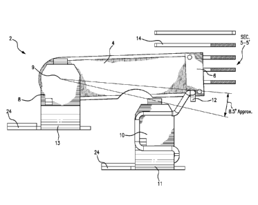
[0004] Figure 1 shows a top perspective, exploded view from the
right side, of the
knife blade switch and its relationship to an arc chute.
[0005] Figure 2 shows a side view of an example embodiment of the
invention,
showing the blade-body fully contacting the jaws, with the arc chute being
cross-
sectioned along the section 5-5' of Figure 5.
100061 Figure 3 shows a side view of an example embodiment of the
invention,
showing the blade end-plate contacting the spring contact, after the blade-
body has
moved upward and fully withdrawn from the jaws, with the arc chute being cross-
sectioned along the section 5-5' of Figure 5.
[0007] Figure 4 shows a side view of an example embodiment of the
invention,
showing the blade end-plate moving upward and no longer contacting the spring
contact,
with the arc chute being cross-sectioned along the section 5-5' of Figure 5.
-2b-
CA 2942658 2020-02-07
CA 02942658 2016-09-13
WO 2015/147824 PCT/US2014/031964
[0008] Figure 5 shows an end view of an example embodiment of the
invention,
showing knife blade switch and its relationship with the arc chute that is
shown with the
section line 5-5'.
[0009] Figure 6 shows a top perspective view from the left side, of an
example
embodiment of the invention, showing the blade-body 4 and the blade end-plate
6.
DESCRIPTION OF EMBODIMENTS OF THE INVENTION
[0010] At the start of opening an electrical switch, the area of the
switch contacts
that carries the electrical current diminishes, causing resistive heating and
melting of the
metal contact material in that area. When the contacts begin to actually
separate, the
electrical field strength in the small gap between the contacts is quite large
and causes the
air molecules to ionize, forming a plasma. The positively charged ions and
negative
electrons of the plasma are accelerated in the high electric field toward the
respective
contacts of opposite polarity and strike the metallic surfaces, causing
spallation,
evaporation and ionization of the metal atoms. An arc then forms between the
contacts,
along the conductive path created by the plasma and metal vapor. Metal atoms
are eroded
and ionized from the contact with the more positive potential, and are
accelerated toward
and deposited on the contact with the more negative potential (that
temporarily exist at
that particular moment in an AC cycle), resulting in arc erosion. As the
switch contacts
continue to separate, the electric field strength between the contacts is
reduced
sufficiently so that the plasma and metal vapor are no longer formed and the
arc is
extinguished. Arc erosion on the contacts of a switch impair good contact
joint integrity
when the switch is fully closed.
[0011] In accordance with an example embodiment of the invention, a knife
blade
switch has copper jaws and a copper blade with a steel end-plate fastened to
the free end
of the blade, the steel end-plate having a higher resistivity than the
resistivity of the
copper blade and copper jaws. As the copper blade is withdrawn from the copper
jaws,
the steel end-plate of the blade remains in contact with a higher resistivity
steel jaw-
spring mounted on and electrically connected to the copper jaws. The
connection of the
steel end-plate of the blade with the steel jaw-spring imposes a greater
resistance path for
the current flowing through the switch than the resistance path through the
copper blade
and copper jaws, so that an arc formed at the plate and jaw-spring has a
diminished
-3-
CA 02942658 2016-09-13
WO 2015/147824 PCT/US2014/031964
current, over what would otherwise occur with a copper blade and jaws, when
the contact
separation occurs. The diminished arc current reduces erosion of the copper
jaws and
copper blade of the switch.
[0012] Figure 1 shows a top perspective, exploded view from the right
side, of the
knife blade switch 2 and its relationship to arc chute 14. The knife blade
switch 2 may be
mounted, for example, on a switchboard or control panel and may be enclosed
within a
safety switch cabinet. The knife blade switch 2 has a simplified construction
to connect
or disconnect a first electrical terminal and a second electrical terminal.
The knife blade
switch includes copper jaws 10 (shown in Figure 2), a steel-jaw spring 12 and
a copper
blade 4. The copper blade has a body with a first end having a pivot 9 mounted
on a
pivot support 8 (shown in Figure 2), and a second, free end with a steel end-
plate 6
fastened to it. The copper jaws 10 are connected to the first electrical
terminal and the
copper blade 4 is connected to the second electrical terminal. The steel end-
plate 6 and
the steel-jaw spring 12 have a higher resistivity than the resistivity of the
copper blade 4
and the copper jaws 10. The connection of the steel end-plate 6 of the blade
with the steel
jaw-spring 12 imposes a greater resistance path for the current flowing
through the switch
than the resistance path through the copper blade 4 and the copper jaws 10. As
a
consequence, any arc formed has a diminished current when the contact
separation
Occurs.
[0013] An arc chute 14 is positioned at a location proximate to where the
steel
end-plate 6 of the blade disengages with the steel jaw-spring 12, to direct
the arc and cool
the hot arc gases. When the switch opens and the steel end-plate 6 moves up
through the
arc chute 14, the arc chute diverts the arc against an arc plate stack, to
split the arc up into
a number of elementary arcs, to dissipate the energy of the arc. The arc chute
14 may be
fastened to the same base that supports the knife blade switch 2.
[0014] Figure 2 shows a side view of an example embodiment of the
invention,
showing the knife blade switch 2 that includes jaws 10 and a blade body 4,
each
composed of a low resistivity metal, such as copper. The blade-body 4 is shown
fully
contacting the jaws 10. The jaws 10 is mounted on the base 24. An end-plate 6
composed of a higher resistivity metal, such as steel or a steel alloy, is
fastened to the free
end of the blade body 4. The steel end-plate 6 has a higher resistivity than
the resistivity
of the copper blade body 4 and copper jaws 10. The arc chute 14 is shown
positioned at a
-4-
CA 02942658 2016-09-13
WO 2015/147824 PCT/US2014/031964
location proximate to where the steel end-plate 6 of the blade disengages with
the steel
jaw-spring 12, to direct the arc and cool the hot arc gases. The jaws 10 may
be coupled to
a first electrical terminal 11. The blade body 4 has a first end mounted on a
pivot 9 and
coupled to a second electrical terminal 13. The pivot support 8 is mounted on
the base
24. The blade body 4 is rotatable about the pivot 9 to electrically engage the
jaws 10 in a
closed position and to electrically disengage from the jaws 10 and a jaw-
spring 12 in an
open position. The jaw-spring 12 and the end-plate 6 have a higher resistivity
than the
blade body 4 and the jaws 10. The jaw-spring 12 is in contact with the end-
plate 6 on the
blade when the blade body 4 is disengaged from the jaws 10 as the blade
rotates toward
the open position. The jaw-spring 12 is mounted on and in electrical contact
with the
jaws 10, and extends upward above the jaws 10, extending beyond the border of
the jaws
in the direction of the arc chute 14. There is a greater resistance pathway
formed when the
end-plate 6 is in contact with the jaw-spring 12 than a resistance path
through the blade
body 4 when engaged with the jaws 10. The low resistivity metal of the blade
body 4 and
jaws 10 may be, for example, aluminum, silver or copper and the higher
resistivity metal
of the end-plate 6 and jaw-spring 12 may be, for example, steel, a steel
alloy, or a
refractory metal such as tungsten, molybdenum, or alloys thereof.
[0015] Figure 3 shows a side view of an example embodiment of the
invention,
showing the blade end-plate 6 contacting the spring contact 12, after the
blade-body 4 has
been moved upward and fully withdrawn from the jaws 10. As the copper blade 4
is
withdrawn from the copper jaws 10, the steel end-plate 6 of the blade remains
in contact
with a higher resistivity steel jaw-spring 12 mounted on the copper jaws 10.
The
connection of the steel end-plate 6 of the blade with the steel jaw-spring 12,
imposes a
greater resistance path for the current flowing through the switch 2 than the
resistance
path through the copper blade 4 and copper jaws 10, so that an arc formed has
a
diminished current when the contact separation occurs. The diminished arc
current
reduces erosion of the copper jaws and copper blade of the switch.
[0016] At least two properties of the material of the switch contacts
affect the
extent of arc erosion. First, the melting point of the contact material will
affect the extent
of arc erosion. A higher melting point material will reduce the extent of
melting caused
by the resistive heating as the switch starts to open. It will also reduce the
extent of
vaporization of the metal atoms when exposed to the ionized air molecules when
the
-5-
CA 02942658 2016-09-13
WO 2015/147824 PCT/US2014/031964
contacts begin to actually separate. The second property of the material is
its hardness. A
contact material having a higher hardness, will more readily resist the
spallation and
evaporation of the metal atoms when exposed to the positively charged ions and
negative
electrons of the plasma.
[0017] The steel end-plate 6 and the steel-jaw spring 12 may be composed
of a
material that has a higher melting point and higher hardness than the melting
point and
hardness of the copper blade 4 and the copper jaws 10. The steel end-plate 6
and the
steel-jaw spring 12 may have a higher melting point material to reduce the
extent of
melting caused by the resistive heating as the switch starts to open. It will
also reduce the
extent of vaporization of the metal atoms when exposed to the ionized air
molecules when
the contacts begin to actually separate. The steel end-plate 6 and the steel-
jaw spring 12
may be composed of a material that has a higher hardness, to more readily
resist the
spallation and evaporation of the metal atoms when exposed to the positively
charged
ions and negative electrons of the plasma.
[0018] By relocating the arc to the steel end-plate 6 and the steel-jaw
spring 12,
which occurs upon separation, arc erosion is substantially eliminated for the
current
carrying copper blade 4 and the copper jaws 10. In this manner, good contact
joint
integrity is maintained when the switch 2 is fully closed.
[0019] Examples of the low resistivity metal composing the blade body 4
and
jaws 10 are shown as follows in Table I. The melting point and hardness of the
example
metals are also shown, for comparison with those for the end-plate 6 and jaw-
spring 12.
Table I
Metal Resistivity Melting Point Vickers
(Ohm Meters) ( C) Hardness
(MN m-2)
silver 1.59x10^8 960 251 MN m-2
copper 1.68x10^8 1083 C 369 MN m-2
aluminum 2.65x10^8 659 167 MN m-2
[0020] Examples of the higher resistivity, higher melting point and higher
hardness metal composing the end-plate 6 and jaw-spring 12 are shown in Table
II:
-6-
CA 02942658 2016-09-13
WO 2015/147824 PCT/US2014/031964
Table II
Metal Resistivity Melting Point Vickers
(Ohm Meters) ( C) Hardness
(MN m-2)
steel 11.8x10^8 1535 608 MN m-2
tungsten 5.6x10^ 8 3370 3430 MN m-2
molybdenum 53.4 x10^8 2620 1530 MN m-2
[0021] Figure 4 shows a side view of an example embodiment of the
invention,
showing the blade end-plate 6 moving upward and no longer contacting the
spring contact
12. An arc chute 14 is positioned at a location proximate to where the steel
end-plate 6 of
the blade disengages with the steel jaw-spring 12, to direct the arc and cool
the hot arc
gases. The arc chute 14 may be fastened to the same base 24 that supports the
switch 2.
The arc chute sends the arc against an arc plate stack, arranged at right
angles to the main
arc column in order to split the arc up into a number of elementary arcs, each
of them thus
generating a minimum arcing voltage due to its elongation.
[0022] Example embodiments of the knife blade switch 2 may be manually
actuated or automatically actuated. Examples of an automatic actuation
mechanism may
include an electrically driven solenoid, gear motor, or linear motor that
rotates the blade-
body 4 about the pivot 9, to either open or close the switch. The application
of such an
electrically driven actuator enables a fast insertion or withdrawal of the
blade end-plate 6
as it engages or disengages with the steel jaw-spring 12. A faster speed in
the air, before
insertion or after withdrawal, will reduce the duration of the arc in the air
and thus the
energy that it dissipates.
[0023] During the interval when the blade end-plate 6 is in contact with
the steel
jaw-spring 12, the current flowing through the switch is reduced because it
must flow
through a greater resistance path. The reduction in the current will diminish
any arc
formed when the contact separation occurs. For example, the relative position
of the
pivot 9 and the top of the jaws 10 shown in Figure 4, may be designed to
enhance the
reduction in the current, based on the estimated speed that an electrically
driven actuator
can move the blade end-plate 6 through the steel jaw-spring 12. By increasing
the
-7-
CA 02942658 2016-09-13
WO 2015/147824
PCT/US2014/031964
duration that the current must flow through the higher resistance path of the
end-plate 6
and the steel jaw-spring 12, more energy is dissipated that would otherwise
contribute to
forming the arc. For example, an estimated angular speed for a particular type
of actuator
may be approximately 3000 degrees per second. In the example shown in Figure
4, there
is an 8.5 degree angular-arc of travel by the blade-body 4 about the pivot 9,
while the
blade end-plate 6 is in contact with the steel jaw-spring 12. The duration of
the higher
resistance contact is therefore 8.5/3000 or 2.8 milliseconds before the arc
can start.
Increasing the angular-arc of travel by the blade-body 4 about the pivot 9,
while the blade
end-plate 6 is in contact with the steel jaw-spring 12, can further reduce the
energy of the
arc formed when the contact separation occurs.
[0024] Figure 5 shows an end view of an example embodiment of the
invention,
showing knife blade switch and its relationship with the arc chute that is
shown with the
section line 5-5'. The arc chute 14 is positioned to direct the arc, and cool
and extinguish
the hot arc gases produced when the blade end-plate 6 separates from the steel
jaw-spring
12. The arc chute 14 may be an arrangement of metal or non-metallic plates
that divide
and cool the arc. Magnetic coils or permanent magnets may be used to deflect
the
electrically charged arc plasma into the arc chute 14.
[0025] Figure 6 shows a top perspective view from the left side, of an
example
embodiment of the invention, showing the blade-body 4 and the blade end-plate
6. The
blade end-plate 6 may comprise two steel plates 6A and 6B, that are riveted by
rivets 6C
and 6D, on to opposite sides of the free end of the blade-body 4.
[0026] Although specific example embodiments of the invention have been
disclosed, persons of skill in the art will appreciate that changes may be
made to the
details described for the specific example embodiments, without departing from
the spirit
and the scope of the invention.
-8-