Note: Descriptions are shown in the official language in which they were submitted.
CA 02942835 2016-09-15
WO 2015/140200
PCT/EP2015/055647
METHOD FOR STARTING A GAS TURBINE
DESCRIPTION
The present invention relates to a method for starting a gas turbine. Such
method is potentially applicable to every kind of gas turbine, such as the
ones
used for mechanical power (compressors or pumps drive) and for power
generation (electrical generators).
A gas turbine is known from the state of the art, comprising a combustion
chamber provided with one or more nozzles. Such nozzles are used to inject
fuel, which is then burned inside the combustion chamber. The hot exhaust
gases that exit the combustion chamber are then used to move an impeller
attached to a shaft, thus providing mechanical work.
An apparatus for regulating the flow of fuel in such gas turbine is also
known.
The apparatus comprises a fuel line, which in operation is connected with a
fuel inlet and with the nozzles of the gas turbine. Indeed, the fuel line has
the
function of transferring fuel from the inlet to the nozzles. A regulating
valve
is placed along the fuel line, so that the flow of fuel can be controlled.
Thus,
in order to start the turbine, the regulating valve is opened to a defined
stroke
and a small flow of fuel is allowed to enter inside the combustion chamber. A
spark then ignites the fuel and, afterwards, the flow of fuel can be increased
further, until a desired operating condition is achieved.
A disadvantage of the prior art is that, in case of a malfunction of the
regulating valve, too much fuel can be allowed inside the combustion
chamber before the ignition. This is potentially extremely dangerous, as it
can
lead to an explosion of the gas turbine or its exhaust duct with high risk of
injuries or fatalities of personnel. For this reason, the known turbines are
provided with a safety device designed to interrupt the flow of fuel in case
of
malfunction. Indeed, such safety device may comprise a flow meter placed on
the fuel line downstream of the regulating valve
1
CA 02942835 2016-09-15
WO 2015/140200
PCT/EP2015/055647
SUMMARY
A first embodiment of the present invention therefore relates to a method of
starting a gas turbine. Such method comprises the step of providing an
apparatus for regulating the flow of fuel in a gas turbine. The apparatus
comprises a main line fluidly connectable with a fuel source and with a nozzle
array for transferring fuel from the fuel source to the nozzle array. The
apparatus also comprises an auxiliary line fluidly connectable with the fuel
source and with the nozzle array for transferring fuel from the fuel source to
the nozzle array.
The method comprises the step of keeping the main line sealed while
increasing the auxiliary line fuel flow rate. The method also comprises the
step of firing the gas turbine while keeping the main line sealed. After the
combustion has started in the gas turbine, and when auxiliary line reaches
about its maximum capacity, the main line is opened to increase the main line
fuel flow rate. The auxiliary line maximum flow rate is less than the main
line
maximum flow rate.
Advantageously, in this way the gas turbine can be started in an intrinsically
safe manner, since the auxiliary line alone does not provide enough fuel to
enable a catastrophic failure of the gas turbine. Only after the fuel
combustion
has taken place the main line is opened.
Another embodiment of the invention relates to an apparatus for regulating
the flow of fuel in a gas turbine. Such apparatus comprises a main line that
can be connected in fluid communication with a fuel source and with a nozzle
array for injecting fuel into a combustion chamber of a gas turbine. The
.. apparatus also comprises a main flow regulator placed on the main line and
configured to vary the flow of fuel on the main line up to a main line
maximum flow rate.
2
CA 02942835 2016-09-15
WO 2015/140200
PCT/EP2015/055647
An auxiliary line is placed in fluid communication with the fuel source and
the nozzle array for transferring fuel from the fuel source to the nozzle
array.
An auxiliary flow regulator is placed on the auxiliary line and is configured
to
vary the flow of fuel on the auxiliary line up to an auxiliary line maximum
flow rate. The auxiliary line maximum flow rate is less than the main line
maximum flow rate.
A third embodiment of the invention relates to a method of upgrading a
previous apparatus for regulating the flow of fuel in a gas turbine. The
previous apparatus is connected to a nozzle array and to a fuel source for
injecting fuel into a combustion chamber of a gas turbine. The previous
apparatus comprises a main line in fluid communication with the fuel source
and the nozzle array, so as to transfer fuel from the fuel source to the
nozzle
array. The previous apparatus also comprises a main flow regulator placed on
the main line and configured to vary the flow of fuel on the main line up to a
main line maximum flow rate.
The method of upgrading the previous apparatus itself comprises the steps of
providing an auxiliary line and placing it in fluid communication with the
fuel
source and with the nozzle array, so as to transfer fuel from the fuel source
to
the nozzle array. The auxiliary is sized so that its maximum flow rate is less
than the main line maximum flow rate. An auxiliary flow regulator is then
placed on the auxiliary line to vary the flow of fuel on the auxiliary line up
to
an auxiliary line maximum flow rate.
Advantageously, this allows to apply the above described method for starting
a gas turbine to an apparatus not specifically designed for it.
Further details and specific embodiments will refer to the attached drawings,
in which:
3
CA 02942835 2016-09-15
WO 2015/140200
PCT/EP2015/055647
- Figure 1 is a schematic representation of an apparatus for regulating the
flow of fuel in a gas turbine according to a first embodiment of the present
invention;
- Figure 2 is a schematic representation of an apparatus for regulating the
flow of fuel in a gas turbine according to a second embodiment of the present
invention;
- Figure 3 is a schematic representation of an apparatus for regulating the
flow of fuel in a gas turbine according to a third embodiment of the present
invention; and
DETAILED DESCRIPTION
The following description of exemplary embodiments refers to the
accompanying drawings. The same reference numbers in different drawings
identify the same or similar elements. The following detailed description does
not limit the invention. Instead, the scope of the invention is defined by the
appended claims.
Reference throughout the specification to "one embodiment" or "an
embodiment" means that a particular feature, structure, or characteristic
described in connection with an embodiment is included in at least one
embodiment of the subject matter disclosed. Thus, the appearance of the
phrases "in one embodiment" or "in an embodiment" in various places
throughout the specification is not necessarily referring to the same
embodiment. Further, the particular features, structures or characteristics
may be combined in any suitable manner in one or more embodiments.
Therefore, an apparatus for regulating the flow of fuel in a gas turbine will
be
described by referring to the attached figures, in which will be indicated
with
the number 1.
4
CA 02942835 2016-09-15
WO 2015/140200
PCT/EP2015/055647
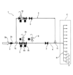
Such apparatus 1 is designed to transfer the fuel to a combustion chamber
"C", which is provided with a plurality of nozzles 3. Indeed, the combustion
chamber may comprise one or more array "N" of nozzles 3. As shown for
example in figure 3, the nozzle array "N" (itself not part of the invention)
comprises a first 3a and a second set 3b of nozzles 3. In the embodiment
shown in figure 3 the first set 3a of nozzles 3 comprises the primary nozzles
3. The second set 3b comprises the secondary nozzles 3.
In further embodiments, not shown, there may be as many set of nozzles 3 as
it is deemed necessary by the project specifications.
The combustion chamber "C" is not considered as part of the present
invention, and will not be described in further detail.
The apparatus 1 comprises a fuel source 2. Indeed, the fuel source 2
comprises one fuel inlet 2a, associated with a respective inlet strainer 2b.
A main line 4 for the transfer of fuel is placed in fluid communication with
the fuel source 2. Also, the main line 4 is placed in fluid communication with
one or more nozzles 3. Indeed, in the context of the present disclosure the
main line 4 is considered to be the path of the fuel between the fuel source 2
and the nozzles 3. It is to be noted that such path may comprise more than one
parallel physical paths between the fuel source 2 and the nozzles 3.
Along the main line 4 is placed a sealing device 5, also referred to as "block
and bleed" in the technical field. The sealing device 5 comprises a set of
valves 5a, 5b, 5c. A first 5a and a second valve 5b are arranged serially
along
the main line 4. A third valve 5c is connected in fluid communication with the
main line 4 between the first 5a and the second valve 5b so that, when
opened, can vent the gas entrapped between the first 5a and the second valve
5b. This arrangement is such that during the functioning of the gas turbine,
the third valve Sc is closed while both the first 5a and the second valve 5b
are
kept open. In this way, fuel can flow along the main line 4. When the gas
5
CA 02942835 2016-09-15
WO 2015/140200
PCT/EP2015/055647
turbine is not working both the first 5a and the second valve 5b are kept
closed, and the third valve Sc is kept open. In this way, any fuel leaks from
the first 5a and the second valve 5b will be allowed to vent away from the
main line 4 by the third valve Sc, thus preventing any potential accumulation
of fuel inside the combustion chamber "C".
A vent valve 6 is present on the main line 4, preferably downstream of the
sealing device 5.
In the embodiment shown in figure 3, the main line 4 branches to reach the
first 3a and the second set 3b of nozzles 3. Indeed, the main line comprises a
main branch 4a which branches into a primary 4b and into a secondary branch
4c. The primary branch 4b is placed in fluid connection with the main branch
4a and with the first set 3a of nozzles 3. Similarly, the secondary branch 4c
is
placed in fluid connection with the main branch 4a and with the second set 3b
of nozzles 3. In this arrangement, the above described sealing device 5 and
vent valve 6 are placed on the main branch 4a of the main line 4.
The main line 4 can comprise an expansion zone 12. As shown in figure 3, the
expansion zone 12 is placed between the main branch 4a and the primary 4b
and secondary branches 4c. A divergent portion 13 connects the main branch
4a to the expansion zone 12. A convergent portion 14 connects each of the
primary 4b and secondary 4c branches to the expansion zone 12.
Advantageously, this helps to dampen any pressure fluctuation on the main
line 4 before it reaches the nozzles 3.
A main flow regulator 7 is placed on the main fuel line 4, preferably
downstream of the sealing device 5. Also, the main flow regulator 7 is placed
downstream of the vent valve 6. Such main flow regulator 7 is configured to
vary the flow of fuel on the main fuel line 4 up to a main line maximum flow
rate. In the embodiment from figure 3, each of the primary 4b and secondary
4c branch is provided with its own flow regulator. With more detail, the
apparatus 1 may comprise a primary flow regulator 7a on the primary branch
6
274322
4b of the main line 4. Similarly, the apparatus 1 may comprise a secondary
flow regulator 7b on the secondary branch 4c of the main line 4. The primary
7a and the secondary flow regulator 7b are substantially similar to the main
flow regulator 7 described above. If the specifications require it, the
primary
7a and the secondary 7b flow regulators may be sized differently. It is to be
noted that in this arrangement no main flow regulator 7 is actually present.
An auxiliary line 8 is placed in fluid communication with the fuel source 2.
The auxiliary line is also placed in fluid communication with at least some of
the nozzles 3, so that it can transfer fuel from the inlet 2a to the nozzles
3.
The purpose of the auxiliary line 8 is to provide an intrinsically safe way to
start the gas turbine, as its maximum flow can be sized so as to be enough to
start the gas turbine but not too much as to create the danger of an
explosion.
With more detail, in one embodiment of the invention the pipes of the
auxiliary line 8 has a lesser internal diameter than the pipes of the main
line
4. Additionally, the auxiliary line 8 comprises a convergent portion 10
directly attached to the main line 4, preferably upstream of the main flow
regulator 7. In particular, the auxiliary line 8 branches from the main line 4
upstream of the sealing device 5.
In the embodiment shown in figure 1, the auxiliary line 8 connects back to the
main line 4 downstream of the main flow regulator 7.
In the embodiment shown in figure 2, the auxiliary line 8 connects back to the
main line 4 upstream of the main flow regulator 7.
In the embodiment shown in figure 3, the auxiliary line 8 connects back to the
primary branch 4b of the main line 4, in particular downstream of the
expansion zone 12. Similarly to the embodiment shown in figure 2, the
auxiliary line 8 connects to the primary branch 4b downstream of the primary
flow regulator 7a. Another variant is possible (not shown in the drawings) in
7
Date Recue/Date Received 2022-01-11
274322
which the auxiliary line 8 connects to the primary branch 4b upstream of the
primary flow regulator 7a.
The auxiliary line 8 comprises a divergent portion 11 directly attached to the
main line 4 or, in case of the embodiment from figure 3, to the primary branch
4b of the main line 4.
The auxiliary line 8 is provided with its own auxiliary sealing device 15.
Such
auxiliary sealing device 15 is substantially similar to the sealing device 5
described above.
The auxiliary line 8 is provided with an auxiliary flow regulator 8, which is
configured to vary the flow of fuel on the auxiliary fuel line 8 itself.
Indeed,
the auxiliary flow regulator 9 ensures that the flow along the auxiliary line
8
can never exceed the auxiliary line 8 maximum flow rate. This maximum flow
rate is less than the maximum flow rate of the main line 4. The auxiliary flow
regulator 9 is in particular placed directly downstream with respect to the
auxiliary sealing device 15.
According to a first embodiment, the auxiliary flow regulator 9 is an orifice.
This embodiment is advantageous for its simplicity, and can be employed if
the fuel composition is relatively constant (a variation of about 5% of the
calorific content of the fuel is admissible). According to another embodiment,
the auxiliary flow regulator 9 is a valve. This allows to vary the composition
of the fuel without constraints, at the cost of greater complexity.
In detail, the auxiliary line 8 maximum flow rate is less than the Lower
Explosive Limit. The Lower Explosive Limit is defined as the minimum
concentration of fuel in a fuel/air mixture such as a spark can ignite the
mixture and cause it to explode. In other words, no explosion is possible if
the fuel concentration is below the Lower Explosive Limit. Such Lower
Explosive Limit generally corresponds to a fuel flow rate of about 15% of the
maximum total flow rate. The exact value of the LEL depends on the
8
Date Recue/Date Received 2022-01-11
274322
physical/chemical properties of the fuel, on the temperature of the air, and
on
other general physical properties so that its precise value can easily be
computed by the person skilled in the art if all such properties are known or
can be reasonably assumed to be inside a specific range (such as is generally
the case during the design of a gas turbine).
The apparatus 1 may also comprise a flame detector (not shown in the
drawings) active on the combustion chamber of the gas turbine. The flame
detector is preferably optical, and ensures that a control system of the
apparatus 1 can react to any changes in the combustion chamber.
In order to start the gas turbine, the main shaft of the gas turbine is
initially
moved by a starting engine (both are not shown in the drawings). Thus an
initial air flow is established in the gas turbine and, in particular, in the
combustion chamber "C". In this way, the combustion chamber "C" is purged
from eventual residue of fuel which may be still inside.
After the purging phase, a spark is started inside the combustion chamber
"C". The fuel flow is then slowly increased inside the combustion chamber
"C". With more detail, the main line 4 is kept sealed, while the fuel flow
rate
in the auxiliary line is increased. In other words, the gas turbine is fired
while
keeping the main line 4 sealed. Indeed, the gas turbine is fired using only
fuel
from the auxiliary line.
With additional detail, in the embodiment shown in figure 2 the main flow
regulator 7 is opened at a preset stroke. The auxiliary flow regulator 9 is
controlled in order to achieve a predetermined pressure value upstream of the
main flow regulator 7. With more detail, the preset pressure value is
preferably not constant, but is a function of the rotational speed of the
turbomachine. Since the main flow regulator 7 is fixed at this stage, the fuel
flow inside the combustion chamber "C" is only a function of the pressure
upstream of the main flow regulator 7.
9
Date Recue/Date Received 2022-01-11
CA 02942835 2016-09-15
WO 2015/140200
PCT/EP2015/055647
The combustion can therefore start in the gas turbine. With additional detail,
the method comprises a step of detecting a flame inside the combustion
chamber. Preferably, such step is performed before the main line 4 opening
step. In particular, such step is performed by the above mentioned flame
detector.
Afterwards, the main line 4 is opened in order to increase the main line 4
fuel
flow rate. With more detail, after the auxiliary flow regulator 9 is
completely
opened the gas turbine is warmed up for several minutes. Afterwards, the
sealing device 5 is gradually opened, in particular with reference to the
first
5a and second valve 5b. The main flow regulator 7 can then be controlled in
order to further increase the flow of fuel inside the combustion chamber "C".
In the embodiments from figure 1 and 3 the startup sequence is similar to the
one described above. However, the auxiliary flow regulator 9 is not controlled
as a function of a preset pressure, but is placed in sonic condition and
targets
a predetermined auxiliary line 8 flow rate directly. Additionally, after the
auxiliary line 8 maximum flow rate is achieved, the main flow regulator 7 is
opened at a preset stroke. Afterwards, the sealing device 5 is gradually
opened, in particular with reference to the first 5a and second valve 5b.
During this phase the auxiliary flow regulator 9 is gradually closed, so that
the total flow rate can remain constant. After the auxiliary flow regulator 9
is
completely closed, the main flow regulator 7 can be controlled in order to
further increase the flow of fuel inside the combustion chamber "C".