Note: Descriptions are shown in the official language in which they were submitted.
CA 02942900 2016-09-15
WO 2015/142526
PCT/US2015/018823
SHAVING RAZOR INTERCONNECTION MECHANISM AND METHOD OF MAKING
SIMPLIFIED INTERCONNECTION
BACKGROUND
FIELD
Embodiments of the invention relate to shaving razors. More specifically,
embodiments
of the invention relate to shaving razors with a simplified cartridge
interconnection feature.
BACKGROUND
Many shaving razors with different handle formations exist. Some disposable
razors
without a replaceable blade cartridge have a molded handle welded to or formed
as part of head
into which one or more blades may be inserted. Such disposable razors are
generally regarded as
providing an inferior shave to razors with replaceable blade cartridges. The
manner in which
cartridges connect to the handle influences both manufacturing costs and shave
quality. The
existing razors generally use quite complex interconnection mechanisms
typically involving
numerous parts including springs, hooks, release buttons that are all
discreetly formed and
require separate manufacture and assembly. This increases the cost and
complexity of the
manufacturing process.
BRIEF DESCRIPTION OF THE DRAWINGS
Embodiments of the invention are illustrated by way of example and not by way
of
limitation in the figures of the accompanying drawings in which like
references indicate similar
elements. It should be noted that different references to "an" or "one"
embodiment in this
disclosure are not necessarily to the same embodiment, and such references
mean at least one.
Fig. 1 is an exploded view of a razor of one embodiment of the invention.
Fig. 2 is a sectional exploded view of the razor of Figure 1.
Fig. 3 is a sectional view illustrating the interconnection according to one
embodiment of
the invention.
Fig. 4 is an exploded view of an alternative embodiment of the razor handle.
Fig. 5 is a cutaway view of a razor handle with the embodiment of Fig. 4.
1
CA 02942900 2016-09-15
WO 2015/142526
PCT/US2015/018823
DETAILED DESCRIPTION
Fig. 1 is an exploded view of a razor of one embodiment of the invention. A
base
member 102 is unitarily injection molded from a suitable thermoplastic.
Suitable thermoplastics
include resins having sufficient rigidity once cured to limit flexion of the
handle such that good
control of a razor cartridge attached thereto can be maintained. One suitable
thermoplastic is
glass-impregnated nylon with a glass content of 10-30% by weight of the
mixture. This
thermoplastic has been found to have suitable strength and rigidity
characteristics to form a base
layer for one embodiment of the instant invention.
Base member 102 defines one or more interior pockets 116 to receive mass
increasing
members 106 that increase the weight of the handle and therefore improve the
tactile sensation
for a user. In one embodiment, the pockets 116 are sized such that the weights
retain the weights
in a pressure fit relation such that the wall or ends of the pockets exert a
force on the weight 106
to retain it within the pocket. In one embodiment, the weights are inserted
into the pockets after
the base member 102 is injected and cured. In an alternative embodiment, the
combined weights
106 and base 102 are formed by insert molding. While in the shown embodiment,
three internal
pockets 116 (and three weights 106) are present, other configurations of
weights and pockets are
within the scope and contemplation of the invention. Base member 102 also has
formed as a part
thereof, in the single molding operation, an interconnection feature 122
formed to engage a blade
cartridge. Interconnection feature 122 is described in greater detail with
respect to Figs. 2 and 3
below.
In one embodiment, elastomeric reinforcement 104 is over molded onto base
member
102 in a second injection during manufacture. The elastomeric reinforcement
104 improves the
tactile sensation experienced by a user holding the razor and supports the
interconnection feature
122 to reduce the risk that it becomes permanently deformed during use.
Additionally, the
elastomeric reinforcement 104 provides additional retention of weights 106
within pockets 116.
It is preferred that weights 106 pressure fit into pockets 116 so that the
elastomeric reinforcement
is not the sole retaining feature, but the pressure fit is not essential to
all embodiments of the
invention.
A cartridge 108 includes a plurality of shaving blades that form part of a
blade head. The
blade head is coupled to an injection-molded yolk having a male member 118
extending
therefrom. Male member 118 defines a recess 128 that can receive
interconnection member 122.
2
CA 02942900 2016-09-15
WO 2015/142526
PCT/US2015/018823
The shape and construction of the head can have myriad different forms,
including those
described in copending application Serial No. 13/173,911 or United States
Patent No. 8,479,398.
The cartridge interconnection features, the male member 118 with defined
recess 128, are
independent of the form of the head.
Elastomeric reinforcement 104 is selected from a group of thermoplastic
elastomers
(TPE' s) having favorable adhesive qualities relative to the thermoplastic
selected for the base
member. In one embodiment, the elastomer TC5PAZ available from Kraiburg TPE
Corporation
is selected. During manufacture, the TPE is injected at high temperature,
which improves the
bonding characteristics with the base member 102. In addition to the natural
adhesion between
elastomeric reinforcement 104 and base member 102, base member 102 may define
interstitial
voids into which the elastomeric resin flows during manufacture. The cured
resin then further
acts as an anchor within those interstitial voids to prevent delamination of
the elastomeric
reinforcement 104 from base member 102.
Fig. 2 is a sectional exploded view of a razor of one embodiment of the
invention. Base
member 102 is shown with mass increasing members 106 residing in pockets
therein.
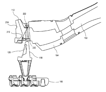
Additionally, a female receiver 232 defined by base member 102 can be seen.
Female receiver
232 is dimensioned to receive male member 118 of blade cartridge 108.
Interconnection
member 112 includes a living hinge 212 and a tine 222. Living hinge 212 is
manufactured to
bias tine 222 into female receiver 232 such that when male member 118 is
inserted into the
female receiver 232, the tine 222 engages (seats within) recess 128.
Elastomeric reinforcement 104 includes a living hinge reinforcement portion
214 that
supports the interconnection member 112. Portion 214 increases the bias of
living hinge 212
into female receiver 232. Portion 214 also reduces the risk that living hinge
212 will move
beyond the elastic region of the underlying material into the plastic region
resulting in permanent
deformation. It has been found that this construction allows the living hinge
to endure thousands
of cycles without breakage.
While in one embodiment, the living hinge 212 is supported by the elastomeric
reinforcement portion 214, in other embodiments, other resilient members could
be used. For
example, a spring may reside in a spring housing that is molded as part of the
base member. In
one embodiment, the spring would reside forward of the living hinge and bias
it toward the
female receiver. In this context, "forward" of the living hinge is deemed to
mean the direction
3
CA 02942900 2016-09-15
WO 2015/142526
PCT/US2015/018823
closer to the head end of the handle. The spring hosing may be sealed with a
snap fit cover.
Generally, the selected resilient member, however constituted, exerts a bias
force on the living
hinge as described and also helps to prevent permanent deformation of the
interconnection
member.
Fig. 3 is a sectional view illustrating the interconnection according to one
embodiment of
the invention. In this figure, elastomeric reinforcement member 104 is shown
residing on base
member 102. Interconnection feature 112 with its living hinge 212 can be seen
with its tine 222
extending into female receiver 232. Interconnection reinforcement portion 214
is shown
supporting living hinge 212 and the remainder of interconnection feature 112.
When male
member 118 of blade cartridge 108 is inserted into female receiver 232, living
hinge 212 flexes
to allow the leading edge of male member 118 to pass and then the bias force
of living hinge 212
and reinforcement portion 214 bias the tine into engagement of recess 128.
Blade cartridge 108
is then locked in place and ready for use. To remove the blade cartridge, the
user need merely
apply force to interconnection feature 112 to overcome the bias force of
living hinge 212 and
reinforcement portion 214 to release the cartridge 108.
Fig. 4 is an exploded view of an alternative embodiment of the razor handle.
In this
embodiment, base member 402 defines a single pocket 426 to receive mass
increasing member
406, and pocket housing 436 provides additional structural support for weight
406. Weight 406
is pressure fit into pocket 426 after the molding of base layer 402. In one
embodiment, weight
406 can be inserted directly into pocket 426 from the bottom side of member
402. After
insertion, the elastomeric reinforcement layer 404 is over molded onto base
member 402.
Interconnection feature 412 of base member 402 is identical to the analogous
feature described
with reference to Figs. 1-3.
Fig. 5 is a cutaway view of a razor handle with the embodiment of Fig. 4. Base
layer 402
defines a weight pocket 426 and is molded as part of pocket cover 436. In this
view, living hinge
512 and tine 522 of connection feature 412 can be seen. Elastomeric
interconnection
reinforcement portion 514 is also shown.
The described embodiments provide a high performance razor with an easy to use
and
low cost interconnection for replaceable blade cartridges. The handle is
manufactured by
injection molding, the base layer insertion of the weights within the one or
more weight pockets
4
CA 02942900 2016-09-15
WO 2015/142526
PCT/US2015/018823
defined within the base layer followed by the over molding of an elastomeric
reinforcement
layer. The simplicity of this manufacturing process yields a highly cost
efficient product.
In the foregoing specification, the embodiments of the invention have been
described
with reference to specific embodiments thereof. It will, however, be evident
that various
modifications and changes can be made thereto without departing from the
broader spirit and
scope of the invention as set forth in the appended claims. The specification
and drawings are,
accordingly, to be regarded in an illustrative rather than a restrictive
sense.
5