Note: Descriptions are shown in the official language in which they were submitted.
CA 02943480 2016-09-21
WO 2015/144591
PCT/EP2015/055971
INTEGRAL KEG CONNECTOR
Technical Field
[0001] The present invention relates to keg connectors for rapidly and easily
connecting a
beer keg to a dispensing line and to a pressurized gas line. It concerns in
particular a cheap,
re-usable keg connector adapted to the new evolution of beer keg designs.
Background for the invention
[0002] When beer or malt based fermented beverages (collectively referred to
herein as
"beer") are widely distributed stored in bottles and metal cans, there is a
marked preference
by the public for beers served directly on tap from a keg, referred to as
draught (or draft)
beer. Since draught beer was traditionally served in large volumes in public
houses (pubs)
and restaurants, large capacity metal kegs were traditionally used, typically
50 I kegs
(= 11 Imperial gallons). In recent years, however; a reduction of the kegs
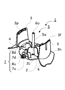
capacity offered on
the market has been observed. There are two main factors explaining this
trend.
[0003] First, brewers have developed various solutions for offering draught
beer to
particulars with specifically designed home appliances. It is clear that if 50
I kegs can be
emptied reasonably rapidly in a pub, this is not the case for home appliances.
Hence, smaller
kegs of 5 to 15 I capacity were developed. Such home appliances are often
referred to as
"table top dispensers" because they are small enough to stand on top of a
table.
[0004] Second, even in pubs, the tastes of the consumers have shifted from
traditional lager
beers towards special beers, with more specific flavours. This diversification
of the types of
beers offered for consumption in pubs has pushed brewers to store their
special beers in
smaller capacity kegs, ranging from 8 to 25 I kegs. Since such kegs are too
large to stand on
top of a counter, and probably too small to justify storing them in a basement
far away from
the tap, they are usually stored directly under the tapping column, usually in
a refrigerated
chamber. For this reason and by opposition to the expression "table top
dispensers", such
dispensing systems used in pubs are often referred to as "under the counter
dispensers".
-1-
[0005] With the reduction of kegs capacity, however, the cost of packaging (=
keg) per litre of
beer sold increased accordingly. Alternative solutions to metal kegs had to be
developed,
typically replacing metal kegs by polymeric kegs made for example of PET.
Furthermore, since
draught beers require a pressurized gas to drive the dispensing of the beer
out of the keg,
and pressurized CO2 bottles used in pubs are not readily available for home
appliances,
solutions were proposed to use air compressors as source of pressurized gas
instead. To avoid
any contact between air and the beer, dispensing bag-in-containers have been
used, wherein
the beer is contained in a flexible inner bag inserted in an outer, rigid
container, and
pressurized gas is injected into the space between the inner bag and outer
container to
collapse the inner bag and drive the beer out of the bag. As illustrative
examples, integrally
blowmoulded polymeric dispensing bag-in-containers are disclosed in
W02008129018,
W02008129016, W02008129012, W02008129015, or W02008129013.
[0006] Regardless of its size, before use a beer keg must be connected to a
dispensing line
and to a source of pressurized gas. Home appliances have been designed with
their own
specific solution for rapidly connecting a dispensing line and a gas source to
the interior of
the kegs (cf. e.g., W02012056018). In some cases, the source of pressurized
gas is stored in
the keg itself, but this solution is rather expensive and to date
implementable in quite small
kegs only (cf. e.g., W09947451, W02007/108684). In pubs, however, although the
kegs
designs have changed dramatically as discussed above, the same equipment as
for large 50 I
kegs is often still being used downstream from the keg, including the keg
connector, the
dispensing line and gas duct, and draught column and tap. Conventional keg
connectors are
usually made of metal, are heavy, complex and expensive. Examples of
conventional keg
connectors are disclosed in W09407791, US3545475, DE9109177U. They are ill-
fitted for
smaller polymeric kegs, typically of 8 to 25 I kegs. Some solutions have been
proposed to
replace conventional keg connectors with simpler connectors.
[0007] W02007/108684 discloses a simplified keg connector comprising a single
connection
to a dispensing tube. The keg connector could be designed without a connection
to a
pressurized gas tube because the pressurized gas source is stored in a
container located inside
the keg. Absent a connection to a pressurized gas source, the requirements, in
particular
-2-
Date Recue/Date Received 2022-06-01
mechanical, clamping, and sealing properties, on the keg connector are
substantially reduced,
and the size thereof could be reduced accordingly. Numerous connectors for
coupling a single
dispensing duct to a container comprising no pressurized gas connection have
been disclosed
in fields other than beer kegs, such as in US6871679, EP2012052, or
W0200107819, but are
not suitable for a quick connection of a beer keg to both a dispensing line
and a pressurized
gas source.
[0008] FR1334267 and W002079075 disclose keg connectors which are as bulky and
complex
as conventional keg connectors. EP1347936 discloses a small size keg connector
comprising
a connection to both a source of pressurized gas and a dispensing tube. The
keg connector
of EP1347936, however, is not connected to a closure of the keg, as it acts as
a closure per
se. Each new keg is sold with such connector already clamped into position
with a new
dispensing line coupled thereto. A keg connector concomitantly acting as
closure Is also
disclosed in US2011210148 , but in this case, the connector is reversibly
coupled to a
container by a thread and can be removed therefrom and used with a new
container.
[0009] There remains a need in the art for re-usable keg connectors adapted
for small size
kegs (e.g., 8 to 25 I capacity), generally made of polymer, which are cheap,
light, safe and easy
to connect to a new keg and disconnect to a spent keg. The present invention
proposes such
keg connector. These and other advantages are discussed more in details in the
following
sections.
Summary of the invention
[0010] In particular, the present invention concerns a keg connector for
coupling a dispensing
line and a gas line to a keg comprising a closure provided with a sealed
dispensing opening
and with a gas opening, said keg connector comprising:
(a) a
mono-block integral body comprising a top plate structure defined by a
perimeter
and comprising an upper surface (2t) and a lower surface and being provided
with a
clamping system for reversibly coupling the keg connector to the closure of
the keg,
said clamping system comprising:
(i) two
clamping legs jutting out of the lower surface of said top plate structure,
each of said clamping legs having a hinge end integrally linked to two
opposite
-3-
Date Recue/Date Received 2022-06-01
portions of the perimeter of said top plate structure and a free end opposite
the hinge end and comprising at least one protrusion extending towards the
free end of the other of said clamping legs; and
(ii) two
levers jutting out of the upper surface of said top plate structure, each of
said levers having a coupled end integrally fixed at the same two opposite
portions of the perimeter of the top plate structure as the hinge ends of the
two legs, and a free end, such that pressing the distal free ends of the two
levers towards one another reversibly and resiliently drives the two free ends
of the clamping legs away from one another;
(b) a dispensing
tube comprising a lumen in fluid communication with an upstream end
located at the end of an upstream portion of the dispensing tube and a
downstream
end located at the end of a downstream portion of the dispensing tube, said
upstream
portion of the dispensing tube having an outer diameter matching the size of
the
dispensing opening of the closure for insertion therein, and jutting
transversally out
of the lower surface of the top plate structure and being rigid such as to be
able to
break the seal of the dispensing opening by pressing thereon; and
(c) a gas tube comprising a lumen in fluid communication with an
upstream end located
at the end of an upstream potion of the gas tube and a downstream end located
at
the end of a downstream portion of the gas tube, said downstream portion of
the gas
tube having an outer diameter matching the size of the gas opening of the
closure
for insertion therein, and jutting transversally out of the lower surface of
the top plate
structure substantially parallel to the upstream portion of the dispensing
tube.
[0011] In a preferred embodiment, the downstream portion of the dispensing
tube forms an
angle of 70 to 120 , preferably of 80 to 100 , with the upstream portion of
the dispensing tube.
Alternatively or concomitantly, the upstream portion of the gas tube forms an
angle of 70 to
120 , preferably of 80 to 100 , with the downstream portion of the gas tube.
[0012] The downstream portion of the dispensing tube can be reversibly
detachable from the
upstream portion of the dispensing tube. Alternatively or concomitantly, the
upstream portion
of the gas tube can be reversibly detachable from the downstream portion of
the gas tube.
-4-
Date Recue/Date Received 2022-06-01
[0013] In an alternative embodiment, the dispensing tube is an integral part
of the mono-
block integral body. Alternatively or concomitantly, the gas tube is an
integral part of the
mono-block integral body.
[0014] Both or anyone of each of the downstream end of the dispensing tube and
the upstream
end of the gas tube may comprise a connection element in order to facilitate
the coupling
thereof to a dispensing line and gas line, respectively.
[0015] In an embodiment particularly suitable for use with dispensing bag-in-
containers, the
upstream portion of the dispensing tube is located substantially at the
geometrical centroid
of the perimeter of the inner surface of the top plate structure, and the
downstream portion
of the gas tube is located close to the perimeter of the inner surface of the
top plate structure.
[0016] The present invention also concerns an assembly of a keg connector as
defined above
coupled to a container containing a beverage, wherein the container comprises
a body portion
and a neck portion provided with an opening sealed by a closure comprising a
dispensing
opening and a gas opening, characterized in that, the upstream portion of the
dispensing tube
.. is inserted in the dispensing opening of the closure and the downstream
portion of the gas
tube is inserted in the gas opening of the closure, and in that, the keg
connector is reversibly
maintained in a coupling position by the two clamping legs. The closure
generally comprises
a skirt ending in a circumferential ridge. In one embodiment the keg connector
is reversibly
maintained in the coupling position by clamping the protrusions at the free
ends of the
clamping legs beyond said circumferential ridge. In an alternative embodiment,
the neck of
the container comprises a circumferential ring forming a ledge around the
circumference of
the neck region, and wherein the keg connector is reversibly maintained in the
coupling
position by clamping the protrusions at the free ends of the clamping legs
beyond said
circumferential ring.
.. [0017] In a preferred embodiment, the assembly of the present invention is
used in a
dispensing unit usually found in most pubs and bars, with the downstream end
of the
dispensing tube being fluidly connected to an upstream end of a dispensing
line. The
dispensing line comprises a free downstream end and is coupled to a tapping
valve situated
-5-
Date Recue/Date Received 2022-06-01
between the upstream and downstream ends of the dispensing line (15). The
upstream end of
the gas tube is fluidly connected to a downstream end of a gas line, said gas
line comprising
an upstream end connected to a source of pressurized gas.
[0018] The present invention also concerns a method for connecting or
disconnecting a keg
to a tapping valve, the method comprising the following steps:
(a) providing a keg connector as defined above and a container extending
along a
longitudinal axis from a base to a neck portion, the base being separated from
the
neck portion by a body portion, and the neck portion being provided with an
opening
sealed by a closure comprising a sealed dispensing opening and a gas opening;
(b) fluidly connecting the upstream end of the gas tube to a source) of
pressurized gas;
(c) fluidly connecting the downstream end of the dispensing tube to a
dispensing line and
coupling said dispensing line to a tapping valve; and
(d) pressing the keg connector against the closure along the longitudinal
axis such as to
insert the upstream portion of the dispensing tube and the downstream portion
of the
gas tube into the corresponding dispensing opening and gas opening,
respectively,
breaking open in the process the seal of the dispensing opening, until the
protrusions
of the free ends of the clamping legs snap fit into a coupling position with
the closure
of the container to obtain an assembly as discussed above.
[0019] The keg connector thus coupled to a keg can be disconnected from the
keg as follows:
= shutting the fluid communication between the source of pressurized gas and
the gas
tube;
= pressing the two levers towards one another with one hand such as to
drive the two
free ends and their corresponding protrusions of the clamping legs away from
one
another; and
= pulling the connector away from the closure along the longitudinal axis.
-6-
Date Recue/Date Received 2022-06-01
Brief description of the Figures
[0020] For a fuller understanding of the nature of the present invention,
reference is made to
the following detailed description taken in conjunction with the accompanying
drawings in
which:
Figure 1 illustrates a beer keg stored in a cooled closet, comprising a keg
connector connecting
said keg to a dispensing line and to a pressurized gas line;
Figure 2 illustrates a closure suitable for use with a keg connector according
to the present
invention;
Figure 3 shows a perspective (a) top view and (b) bottom view of a keg
connector according to
the present invention; and
Figure 4 shows a dispensing bag-in-container comprising a closure (a) before
and (b) after
connection to a dispensing line and to a gas line by means of a keg connector
according to
the present invention.
Detailed description of the invention
[0021] As shown in Figures 1 and 4(b) the present invention concerns
dispensing containers
or kegs (9) containing a liquid, typically a beverage, such as beer or other
carbonated
beverages, to be dispensed through a dispensing line (15) controlled by a
tapping valve (13t)
and driven by a pressurized gas injected into the container. The source (17g)
of pressurized
gas can be a pressurized bottle containing a gas under high pressure, a gas
compressor,
and/or a gas adsorbed on a solid adsorbent. Depending on the type of container
(9) and of
the liquid contained therein, the gas can be air, carbon dioxide, nitrogen or
the like.
[0022] The container or keg (9) (the two terms being herein considered as
equivalent)
generally extends along a longitudinal axis, Xl, from an opening sealed by a
closure (10) to a
base. The opening is comprised in a substantially cylindrical neck region,
which is separated
from a body portion, usually substantially cylindrical of larger diameter than
the neck region,
by a shoulder forming a transition region, and the body portion is adjacent to
the base. The
container (9) can be a traditional keg, wherein the pressurized gas is
injected into the same
volume which contains the liquid. In this case, a dispensing hollow spear is
generally used
with one end dipped at the lowest part of the liquid in a direction parallel
to the gravitational
-7-
Date Recue/Date Received 2022-06-01
field when in use and the other end coupled to a dispensing opening (50) of a
closure sealing
the opening of the keg. Alternatively, the keg (9) can be a dispensing bag-in-
container as
illustrated in Figure 4 and disclosed in W02008129018, W02008129016,
W02008129012,
W02008129015, or W02008129013, wherein a flexible inner bag is coupled to an
outer
container at the neck region and contains the liquid to be dispensed. A vent
between the inner
bag and the outer container allows pressurized gas to be injected between the
inner bag and
the outer container to delaminate and collapse the inner bag and thus dispense
the liquid
contained therein (cf. Figure 4(b)).
[0023] The connection of a dispensing line (15) and a gas line (17) to the keg
(9) is made very
rapid, easy, and comfortable with the use of a keg connector (1) according to
the present
invention. A keg connector of the present invention can be used several times
with different
kegs, and is extremely cheap to produce and easy to use. In particular, a keg
connector (1)
according to the present invention comprises a mono-block integral body
comprising, on the
one hand, a top plate (2) structure defined by a perimeter and comprising an
upper surface
(2t) and a lower surface (2L) and, on the other hand, a clamping syqtem. The
integral mono-
block body is preferably made of a polymer, more preferably, but not
necessarily, a
thermoplastic polymer such as a polyolefin (e.g., PE, PP), a polyamide (e.g.,
PA6, PA66, PA12),
a polyester (e.g., PET, PEN) and the like. It is advantageously injection
moulded. For smaller
series, 3D-printers can be used to produce the mono-block integral body (2).
The mono-block
integral body comprises an integral clamping system for reversibly coupling
the keg connector
to the closure of a keg. The clamping system comprises:
(a) two clamping legs (3) jutting out of the lower surface (2L) of said top
plate
structure (2), each of said clamping legs having a hinge end (3h) integrally
linked to two opposite portions of the perimeter of said top plate structure
(2)
and a free end (30 opposite the hinge end and comprising at least one
protrusion (3p) extending towards the free end of the other leg, and
(b) two levers (4) jutting out of the upper surface (2t) of said top plate
structure
(2), each of said levers having a coupled end (4c) integrally fixed at the
same
two opposite portions of the perimeter of the top plate structure (2) as the
hinge ends of the two legs, and a free end (40, such that pressing the distal
-8-
Date Recue/Date Received 2022-06-01
free ends of the two levers towards one another reversibly and resiliently
drives
the two free ends (3D of the clamping legs (3) away from one another.
[0024] The keg connector (1) further comprises:
= a dispensing tube (5) comprising a lumen bringing in fluid communication
an
upstream end (6u) located at the end of an upstream portion (5u) of the
dispensing tube and a downstream end (6d) located at the end of a downstream
portion (5d) of the dispensing tube; said upstream portion (5u) of the
dispensing tube has an outer diameter matching the size of the dispensing
opening of a closure for insertion therein, and juts transversally out of the
lower
surface (2L) of the top plate structure and is rigid such as to be able to
break
the seal of the dispensing opening by pressing thereon, and
= a gas tube (7) comprising a lumen bringing in fluid communication an
upstream
end (8u) located at the end of an upstream potion (7u) of the gas tube and a
downstream end (8d) located at the end of a downstream portion (7d) of the
gas tube; said downstream portion (7d) of the gas tube has an outer diameter
matching the size of the gas opening of a closure for insertion therein, and
juts
transversally out of the lower surface (2L) of the top plate structure
substantially
parallel to the upstream portion (5u) of the dispensing tube (5).
[0025] As shown in Figure 4, the keg connector (1) of the present invention
can be coupled to
the closure (10) of a keg (9) by simply pressing it onto said closure in a
direction parallel to a
longitudinal axis, Xl, of the keg. At rest, the protrusions (3p) at the
respective free ends (31)
of the clamping legs (3) are separated by a rest distance, dO. Upon pressing
the keg connector
onto the closure, the clamping legs (3) must pass through at least a broad
section spanning a
distance normal to the longitudinal axis, dl > dO, so that the clamping legs
must be flexed
slightly until the protrusions (3p) are separated by a distance, dl, to pass
through
-9-
Date Recue/Date Received 2022-06-01
CA 02943480 2016-09-21
WO 2015/144591
PCT/EP2015/055971
said broad section. The keg connector reaches its coupling position when the
protrusions
(3p) have passed just beyond said broad section and are able to snap back into
their rest
position separated by a distance, dO, resting adjacent the broad section. The
broad section
can be the closure (10) itself which comprises a skirt (10s) and the clamping
legs are able to
snap back into their rest position when the protrusions reach the ridge (10r)
of the closure
skirt. The keg connector is thus coupled to the closure (10) which is itself
coupled to the keg
(9). Alternatively, the keg (9) comprises a circumferential ring (9r) forming
a ledge around
the circumference of the neck region. Said circumferential ledge forms the
broad section
over which the clamping legs must be flexed to pass further and can snap back
into their
rest position once the protrusions (3p) have passed beyond the ring (9r) (cf.
Figure 4(b)).
[0026] As the clamping legs (3) are sliding along the closure skirt (10s) the
upstream portion
(5u) of the dispensing tube (5) and the downstream portion (7d) of the gas
tube (7) are
concomitantly introduced into the dispensing opening (50) and gas opening
(70),
respectively, of the closure (10), the upstream end (6u) of the dispensing
tube (5) breaking
open the sealed dispensing opening (50) in the process. For this reason, the
upstream
portion (5u) of the dispensing tube (5) and the downstream portion (7d) of the
gas tube (7)
must be parallel to one another, and must be parallel to the longitudinal
axis, Xl, when the
keg connector is moved into coupling position.
[0027] In a preferred embodiment illustrated in Figures 1 and 2, the upstream
portion (7u)
of the gas tube (7) forms an angle of 70 to 120 , preferably of 80 to 100 ;
with the
downstream portion (7d) of the gas tube. In a more preferred embodiment the
upstream
portion (7u) and downstream portion (7d) of the gas tube (7) are substantially
normal. This
allows a lateral connection of the gas line (17) to the keg connector which,
depending on the
configuration of the closet (11) in which the keg can be stored when in use
can be
convenient to save room.
[0028] Similarly, the downstream portion (5d) of the dispensing tube (5) can
form an angle
of 70 to 120 , preferably of 80 to 100'; more preferably about 90 with the
upstream portion
(5u) of the dispensing tube. This configuration has the same advantage of
saving space as
the gas tube (7) discussed supra. It has the drawback, however, that it is
more difficult to
-10-
CA 02943480 2016-09-21
WO 2015/144591
PCT/EP2015/055971
wash a lumen forming a relatively sharp elbow than a straight lumen. This
drawback does
not affect the gas tube which needs not be washed as thoroughly as the
dispensing tube
before use with a new keg. In case a lateral connection of the dispensing line
(15) is desired,
but it is preferred to not have a dispensing tube (5) forming an angle, it is
possible, as
illustrated in Figure 2, to provide a straight dispensing tube (5) with a
downstream end (8d)
located flush with, or even slightly in recess of the upper surface (2t) of
the top plate (2)
structure. As visible in Figure 2(a), a channel can be provided to accommodate
the upstream
portion of a dispensing line (15) ending with a L-shaped connector (15c).
After use, the
dispensing line (15), which is very difficult to wash satisfactorily, is
normally removed and
replaced by a new one, whilst the straight and relatively short lumen of the
dispensing tube
(5) of the keg connector can easily be thoroughly washed before use with a new
keg. Note
that in an alternative embodiment illustrated in Figure 4, the downstream
portion (5d) of the
dispensing tube (5) and/or the upstream portion (7u) of the gas tube (7) can
be coaxial with
their respective upstream portion (5u) and downstream portion (7d),
respectively.
[0029] In an embodiment of the present invention, the dispensing tube (5)
and/or the gas
tube (7) or at least a portion of said dispensing and/or gas tubes is distinct
from the mono-
block integral body, and can be removably assembled thereto. This
configuration is
advantageous in that, in particular the dispensing tube needs not be washed
before a new
use but can simply be removed and replaced by a new one. This allows the use
of dispensing
and/or gas tubes (5, 7) having a relatively sharp angles, with simple
dispensing and/or gas
lines (15, 17) comprising no specific end geometry, contrary to the L-shaped
upstream end
of the dispensing line (15) discussed with respect of the foregoing
embodiment. A simple
flexible polymeric pipe can thus be used as dispensing or gas line (15, 17),
which decreases
the cost of a disposable element of the dispensing unit.
[0030] In an alternative embodiment, illustrated in Figure 2, the whole keg
connector is
made of a single monolithic, integral block including the top plate (2)
structure with its
clamping legs (3) and levers (4), as well as the dispensing tube (5) and the
gas tube (7) in
their entirety, including both upstream and downstream portions thereof.
-11-
CA 02943480 2016-09-21
WO 2015/144591
PCT/EP2015/055971
[0031] In an embodiment particularly suitable for use with dispensing bag-in-
containers,
the upstream portion (5d) of the dispensing tube (5) is located substantially
at the
geometrical centroid of the perimeter of the inner surface of the top plate
structure (2), and
the downstream portion (7d) of the gas tube (7) is located close to the
perimeter of the inner
surface of the top plate structure (2). As shown in Figures 3&4 this
configuration is well
suited for bag-in-containers wherein pressurized gas is injected between the
inner layer
forming a flexible, collapsible bag containing the liquid to be dispensed, and
the outer
container. For this reason, the gas opening (70) in a closure (10) used with
such bag-in-
containers is conveniently located at the level of the rim defining the
perimeter of the mouth
of the container where a vent can be located. The dispensing opening can be
anywhere else
over the mouth of the container, and is conveniently located at the centre
thereof.
[0032] In case of traditional dispensing kegs, wherein pressurized gas,
generally CO2, is
injected into the volume containing the liquid to be dispensed through a
hollow spear, the
dispensing tube (5) is advantageously located close to the centroid of the top
plate (2)
structure, whilst the gas tube (7) should not be too close to the perimeter
thereof, since it
must correspond to a gas opening (70) of a closure which is located over the
opening of the
keg. In some instances, the gas duct (7) and dispensing duct (5) may be
concentric, with the
downstream portion (7d) of the gas duct (7) being enclosed within the upstream
portion (5u)
of the dispensing tube (5).
[0033] When a keg connector (1) according to the present invention is
reversibly coupled to
a keg (9), it is is maintained in its coupled position by means of the
clamping legs (3) snap-
fitted beyond a broad section of the keg, which can be formed by the
circumferential ridge
(10r) forming the free end of the closure skirt (10s) or, alternatively by a
circumferential ring
(9r) formed at the neck region of the keg (9). In its coupled position, the
upstream portion
(5u) of the dispensing duct (5) is engaged in the dispensing opening (50) of
the closure (with
the seal thereof broken open upon introduction of the upstream end (6u) of the
dispensing
tube (5)) and the downstream portion (7d) of the gas tube (7) is engaged in
the gas opening
(70) of the closure. The terms "downstream" and "upstream" are used herein
with reference
to the flow direction of a fluid in the corresponding tubes (viz., liquid in
the dispensing tube
-12-
CA 02943480 2016-09-21
WO 2015/144591
PCT/EP2015/055971
(5) flowing out of the container, and pressurized gas flowing in the gas tube
(7) into the
container).
[0034] The downstream end (6d) of the dispensing tube (5) must be connected to
an
upstream end of a dispensing liner (15); which comprises a free downstream end
(15d) and
is coupled to a tapping valve (13t) located between the upstream and
downstream ends of
the dispensing lines. In a preferred embodiment illustrated in Figure 1, the
assembly formed
by a keg (9) and a keg connector (1) according to the present invention is
used in a tapping
system as can be found in bars and pubs. The keg can be stored under the
counter,
preferably in a closet (11) comprising a cooling system (12) for refrigerating
the beverage
(e.g., beer) contained in the keg. The dispensing line (15) runs from the
downstream end
(6d) of the dispensing tube (5) of the keg connector, through a tapping column
and is
coupled to a tapping valve system (13t) which can be, for example, a pinch
valve as
disclosed e.g., in EP2452914.
[0035] Similarly, when the keg connector (1) is in its coupled position with
the keg, the
downstream portion (7d) of the gas tube (7) is inserted in the gas opening
(70) of the closure
(10). The upstream end (8u) of the gas tube (7) is connected to a gas line
(17) which is
coupled to a source (17g) of pressurized gas, such as a bottle containing gas
under high
pressure (cf. Figure 1), or to a compressor (cf. Figure 4). Injection of
pressuried gas into the
keg (9) through the gas line (17) and gas tube (7) drives the flow of liquid
contained in the
keg through the dispensing tube (5) and dispensing line (15) to the tapping
valve (13t).
When the latter is open, the liquid is free to flow out of the downstream end
(15d) of the
dispensing line (15) into a glass or any other recipient (cf. Figure 4(b)).
Figure 4 shows the
example of a dispensing bag)-in-container which dispensing mechanism has been
discussed
supra. In case of a traditional keg, a spear is required to lead the flow of
liquid from the
most remote portion of the container from the keg opening in a direction
parallel to the
gravity field when the keg is in dispensing position (i.e., if the keg stands
up vertical with its
opening at the highest point, then the spear must reach close to the base of
the container. If
the keg is held in a tilted position, then the free end of the spear must
reach the lowest
point of the keg. If the keg is held vertically with its opening facing
downwards, then no
-13-
CA 02943480 2016-09-21
WO 2015/144591
PCT/EP2015/055971
spear is needed). But with such configuration, injection of a pressurized gas
is generally not
necessary since dispensing is driven by gravity.
[0036] A keg connector according to the present invention can be used
repeatedly with
different kegs (9) and is not disposable with each single keg. For this
reason, it must be
easily removable from an empty keg in order to the coupling thereof to a new
keg. To
facilitate the removal of a keg connector from an empty keg, the keg connector
comprises
two levers (4) which are a continuation of the clamping legs (3) extending on
the opposite
surface of the top plate structure (2), at the upper surface (2t) thereof.
After closing the
communication between the keg and the source (17g) of pressurized gas, the keg
connector
(1) can be easily removed by pressing the free ends (4f) of the two levers (4)
towards one
another, so that the protrusions (3p) at the free ends (3f) of the clamping
legs (3) are driven
away from each other, to a distance of dl or greater. In such configuration,
the keg
connector can be removed along the longitudinal axis, X1 , and can pass over
the broad
section without hindrance. After some washing, the keg connector is ready for
use with a
.. new keg.
[0037] A keg connector (1) according to the present invention is extremely
cheap to produce
and can be used repeatedly with several kegs. It is very simple and rapid to
use, requiring no
complex movements of twisting or rotating for reversibly coupling it to a keg,
but a simple
translation along the longitudinal axis of the container suffices until the
clamping legs (3)
snap fit into position, with the dispensing tuber (5) and gas tube (7) engaged
in the
respective dispensing opening (50) and gas opening (70) of the keg closure
(10). It is very
compact, taking very little room when coupled to a keg. The removal thereof is
very easy too,
making it a perfect replacement to the conventional bulky keg connectors or to
the
disposable, single use connectors of the prior art.
[0038] The following table lists the reference numbers used in the Figures.
Description
1 keg connector
2 top plate structure
21_ lower surface of top plate structure 2
2t upper surface of top plate structure 2
-14-
CA 02943480 2016-09-21
WO 2015/144591
PCT/EP2015/055971
3 clamping leg
3f clamping leg free end
3h clamping leg hinge end
3p clamping leg protrusion
4 lever
4c lever coupled end
4f lever free end
dispensing tube
5d downstream portion of dispensing tube
5u upstream portion of dispensing tube
6d downstream end of dispensing tube
6u upstream end of dispensing tube
7 gas tube
7d downstream portion of gas tube
7u upstream portion of gas tube
8d downstream end of gas tube
8u upstream end of gas tube
9 keg, container
closure
11 keg closet
12 cooling system
13 tapping column
13t tap valve
dispensing line
15c connection element between dispensing line 15 and dispensing tube 5
15d downstream end of dispensing line
17 gas line
1 7c connection element between gas line 1 7 and gas tube 7
17g source of pressurized gas
50 dispensing opening of closure 1 0
70 gas opening of closure 10
-1 5-