Language selection

Search

Patent 2943742 Summary

Third-party information liability

Some of the information on this Web page has been provided by external sources. The Government of Canada is not responsible for the accuracy, reliability or currency of the information supplied by external sources. Users wishing to rely upon this information should consult directly with the source of the information. Content provided by external sources is not subject to official languages, privacy and accessibility requirements.

Claims and Abstract availability

Any discrepancies in the text and image of the Claims and Abstract are due to differing posting times. Text of the Claims and Abstract are posted:

  • At the time the application is open to public inspection;
  • At the time of issue of the patent (grant).
(12) Patent: (11) CA 2943742
(54) English Title: ELECTRICAL ENCLOSURE WITH VENTILATION STRUCTURE
(54) French Title: BOITIER ELECTRIQUE DOTE D'UNE STRUCTURE DE VENTILATION
Status: Granted
Bibliographic Data
(51) International Patent Classification (IPC):
  • H02B 1/56 (2006.01)
  • H02B 1/30 (2006.01)
(72) Inventors :
  • PROHASKA, RICHARD D. (United States of America)
  • ENSLEY, JEFF B. (United States of America)
(73) Owners :
  • EATON INTELLIGENT POWER LIMITED (Ireland)
(71) Applicants :
  • EATON CORPORATION (United States of America)
(74) Agent: BERESKIN & PARR LLP/S.E.N.C.R.L.,S.R.L.
(74) Associate agent:
(45) Issued: 2023-08-29
(22) Filed Date: 2016-09-29
(41) Open to Public Inspection: 2017-05-20
Examination requested: 2021-09-24
Availability of licence: N/A
(25) Language of filing: English

Patent Cooperation Treaty (PCT): No

(30) Application Priority Data:
Application No. Country/Territory Date
62/258,138 United States of America 2015-11-20
15/180,461 United States of America 2016-06-13

Abstracts

English Abstract

An electrical equipment enclosure includes a cabinet defining a storage compartment configured to contain electrical equipment. The cabinet has an array of vent openings communicating the storage compartment with the exterior of the cabinet. The enclosure further includes a box structure having a first open side received over the vent openings, a first closed side opposite the first open side, a second closed side reaching from first open side to the first closed side, and a second open side opposite the second closed side. A baffle is located in the box structure between the first open side and the second open side.


French Abstract

Une enceinte de matériel électrique comprend une armoire définissant un espace de rangement configuré pour contenir le matériel électrique. Larmoire comprend un réseau douvertures dévent établissant la communication entre lespace de rangement et lextérieur de larmoire. Lenceinte comprend une structure caisson ayant un premier côté ouvert reçu sur les ouvertures dévent, un premier côté fermé opposé au premier côté ouvert, un deuxième côté fermé sétendant du premier côté ouvert au premier côté fermé, et un deuxième côté ouvert opposé au deuxième côté fermé. Une chicane est située dans la structure caisson entre le premier et le deuxième côté ouvert.

Claims

Note: Claims are shown in the official language in which they were submitted.

What is claimed is:
1. An electrical equipment enclosure, comprising:
a cabinet defining a storage compaitment configured to contain electrical
equipment, the
cabinet having a vent opening communicating the storage compaitment with an
exterior of the
cabinet;
a box structure having a first open side received over the vent opening, a
first closed side
opposite the first open side, a second closed side extending from the first
open side to the first
closed side, and a second open side opposite the second closed side; and
a baffle located in the box structure between the first open side and the
second open side,
wherein the baffle is joined to the box structure at a corner where the first
open side intersects the
second open side, reaches inward from the corner in a direction diagonally
toward an opposite
corner where the first closed side intersects the second closed side, and has
a free end spaced
from the sides of the box structure, whereby the baffle is interposed
diagonally between the first
open side and the second open side such that the baffle and the box structure
define a convoluted
air flow path from the vent opening through the first open side of the box
structure, inward
through the box structure from the first open side toward and around the free
end of the baffle,
and further through the box structure from the free end of the baffle to the
second open side to
ventilate heat from the storage compai intent and to inhibit debris from
passing through the box
structure oppositely along the convoluted air flow path and entering the
storage compai intent
through the vent opening.
2. An electrical equipment enclosure as defined in claim 1, wherein the
second open side of
the box structure has an outlet opening reaching partially across the second
open side of the box,
and the baffle reaches across and beyond the outlet opening.
3. An electrical equipment enclosure as defined in claim 1, wherein the
baffle has a major
section reaching diagonally across the box structure.

4. An electrical equipment enclosure as defined in claim 1, wherein the
baffle has a corner
at the free end, and further has a flange section projecting diagonally from
the corner toward the
second open side of the box structure.
5. An electrical equipment enclosure as defined in claim 1, wherein the box
structure has an
imperforate top wall panel, and further has a bottom wall panel with drain
openings.
6. An electrical equipment enclosure as defined in claim 1, wherein the
cabinet has a door
reaching across an open front side of the storage compaitment, the cabinet
further has a rear wall
panel facing outward from the cabinet in a rearward direction, and the second
open side of the
box structure faces outward from the box structure in the rearward direction.
7. An electrical equipment enclosure as defined in claim 6, wherein the
cabinet is mounted
on a building wall with the rear wall panel facing the building wall.
8. An electrical equipment enclosure as defined in claim 1, wherein the box
structure
includes horizontal shelf structures spaced apart vertically from each other
within the box
structure.
9. An electrical equipment enclosure as defined in claim 8, wherein the
baffle is vertically
elongated, and the shelf structures are located vertically along a common
horizontal side of the
baffle.
10. An electrical equipment enclosure as defined in claim 8, wherein the
baffle reaches
across the box structure diagonally between the vent opening and the outlet
opening, and the
shelf structures are located between the baffle and the vent opening.
11. An electrical equipment enclosure as defined in claim 8, wherein the
shelf structures have
triangular shapes reaching diagonally across the box structure.
6

12. An electrical equipment enclosure as defined in claim 8, wherein the
shelf structures have
drain openings.
13. An electrical equipment enclosure, comprising:
a cabinet defining a storage compaltment configured to contain electrical
equipment, the
cabinet having a vent opening communicating the storage compai anent with
an exterior of the
cabinet, a door reaching across an open front side of the storage compaitment,
and a rear wall
panel facing outward from the cabinet in a rearward direction;
a box structure having a first open side received over the vent opening, a
first closed side
opposite the first open side, a second closed side extending from the first
open side to the first
closed side, and a second open side opposite the second closed side, the
second open side having
an outlet opening facing outward from the box structure in the rearward
direction; and
a baffle located in the box structure between the first open side and the
second open side,
wherein the baffle is joined to the box structure at a corner where the first
open side intersects the
second open side, reaches inward from the corner in a direction diagonally
toward an opposite
corner where the first closed side intersects the second closed side, and has
a free end spaced
from the sides of the box structure, whereby the baffle is interposed
diagonally between the first
open side and the second open side such that the baffle and the box structure
define a convoluted
air flow path from the vent opening through the first open side of the box
structure, inward
through the box structure from the first open side toward and around the free
end of the baffle,
and further from the free end of the baffle through the box structure to the
second open side, to
ventilate heat from the storage compaitment and to inhibit debris from passing
through the box
structure oppositely along the convoluted air flow path and entering the
storage compaitment
through the vent opening.
14. An electrical equipment enclosure as defined in claim 13, wherein the
cabinet is mounted
on a building wall with the rear wall panel facing the building wall.
15. An electrical equipment enclosure as defined in claim 13, wherein the
box structure
includes shelf structures spaced apart vertically from each other within the
box structure.
7

16. An electrical equipment enclosure as defined in claim 15, wherein the
baffle is vertically
elongated, and the shelf structures are located vertically along a common
horizontal side of the
baffle.
17. An electrical equipment enclosure as defined in claim 15, wherein the
baffle reaches
across the box structure diagonally between the vent opening and the outlet
opening, and the
shelf structures are located between the baffle and the vent opening.
18. An electrical equipment enclosure as defined in claim 15, wherein the
shelf structures
have triangular shapes reaching diagonally across the box structure.
19. An electrical equipment enclosure as defined in claim 15, wherein the
shelf structures
have drain openings.
20. An electrical equipment enclosure as defined in claim 15, wherein the
box structure has
an imperforate top wall panel, and further has a bottom wall panel with drain
openings.
8

Description

Note: Descriptions are shown in the official language in which they were submitted.


ELECTRICAL ENCLOSURE WITH VENTILATION STRUCTURE
Related Applications
[0001] Not applicable.
Technical Field
[0002] This technology relates to an enclosure for containing electrical
equipment.
Background
[0003] Electrical equipment may be installed in an enclosure. Such an
enclosure may be
mounted on a wall, either indoors or outdoors, and may be configured for
ventilation.
Summary
[0004] An electrical equipment enclosure includes a cabinet defining a
storage
compaitnient configured to contain electrical equipment. The cabinet has at
least one vent
opening communicating the storage compaitnient with the exterior of the
cabinet. The enclosure
further includes a box structure having a first open side received over the
vent opening. The box
structure further has a first closed side opposite the first open side, a
second closed side reaching
from first open side to the first closed side, and a second open side opposite
the second closed
side. A baffle is located in the box structure between the first open side and
the second open side.
Brief Description of the Drawings
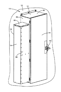
[0005] Figure 1 is a front perspective view of one embodiment of an
electrical enclosure
mounted on an exterior building wall 12.
[0006] Figure 2 is an exploded front perspective view of parts of the
enclosure 10 of Fig.
1.
[0007] Figure 3 is a rear perspective view of the baffle box 16 shown in
Fig. 1.
[0008] Figure 4 is a sectional view of the enclosure 10 of Fig. 1.
[0009] Figure 5 is an enlarged sectional view of the baffle box 16 shown
in Fig. 4.
1
Date Recue/Date Received 2021-09-24

CA 02943742 2016-09-29
[0010] Figure 6 is a different enlarged sectional view of the baffle box 16
shown in Fig.
4.
Detailed Description
[0011] The apparatus illustrated in the drawings includes parts that are
examples of the
elements recited in the claims. The illustrated apparatus thus includes
examples of how any
person skilled in the art can make and use the claimed invention. It is
described here to meet
the enablement and best mode requirements of the patent statute without
imposing limitations
that are not recited in the claims.
[0012] As shown in Fig. 1, an electrical enclosure 10 is mounted on a wall
such as, for
example, an exterior building wall 12. The enclosure 10 includes a cabinet 14
and a baffle
box 16. The cabinet 14, which is configured to contain electrical equipment
such as circuit
switching devices or the like, has vent openings 19 (Fig. 2). The baffle box
16 is received
over the vent openings 19 in the cabinet 14, and has an outlet opening 21
(Fig. 3)
communicating the vent openings 19 with the exterior environment.
[0013] The cabinet 14 in the illustrated example includes a rectangular
wall panel
structure defining a storage compartment 25 (Fig. 4) for containing the
electrical equipment.
The wall panel structure includes a rear wall panel 30, top and bottom wall
panels 32 and 34,
and two opposite side wall panels 36 and 38. A door 40 reaches across an open
front side 41
of the storage compartment 25.
[0014] In the illustrated example, the cabinet 14 is configured to contain
switchable
electrical equipment, such as circuit breakers. The first side wall panel 36
supports an
operating handle assembly 44 that is configured to operate accordingly. The
second side wall
panel 38 includes the vent openings 19. In the given example, the vent
openings 19 all have
the same rectangular shape and size, and are arranged in adjacent pairs that
are equally
spaced apart in two vertical rows, as shown in Fig. 3. Other shapes, sizes,
and patterns are
possible in alternative embodiments.
[0015] The baffle box 16 in the illustrated example also has a rectangular
wall panel
structure. This includes top and bottom wall panels 50 and 52, an outer side
wall panel 54,
and front and rear side wall panels 56 and 58. The top wall panel 50 is
imperforate, and thus
9183596v1 2

CA 02943742 2016-09-29
provides the box 16 with a closed top. The bottom wall panel 52 has drain
openings 59. The
outer side wall panel 54 is imperforate to provide a closed outer side of the
box 16, and faces
across the inside of the box 16 toward an open inner side 61. The front side
wall panel 56 is
imperforate to provide a closed front side of the box 16. The rear side wall
panel 58 also is
imperforate, but reaches only partly from the outer side wall panel 54 to the
open inner side
61. This provides the box 16 with an open rear side at which the outlet
opening 21 reaches
from the outer side wall panel 58 to the open inner side 61.
[0016] As best shown in Fig. 3, the wall panel structure of the box 16
further includes a
frame structure 70 at the open inner side 61. The frame structure 70 has an
array of vent
openings 71 with the same size, shape, and arrangement as the vent openings 19
in the
cabinet 14. However, as with the vent openings 19 in the cabinet 14, other
shapes, sizes, and
patterns of vent openings in the baffle box 16 are possible in alternative
embodiments. A
greater or lesser number of vent openings, as well as only a single vent
opening, also could be
provide at the cabinet 14 and/or the baffle box 16 in alternative embodiments.
[0017] As best shown in Figs. 4 and 5, the baffle box 16 further includes
an inner wall
panel configured as a baffle 80. The baffle 80 in the illustrated example
reaches fully or
substantially fully throughout the height of the box 16 between the top and
bottom wall
panels 50 and 52, and partially across the width of the box 16 between the
open and closed
sides 61 and 54.
100181 A rear flange section 82 (Fig. 5) of the baffle 80 is fastened to
the frame structure
70 beside the outlet opening 21. A major section 84 of the baffle 80 has a
linear cross-
sectional configuration, and projects from the rear flange section 82
diagonally across the
inside of the box 16. A front flange section 88 of the baffle 80 also has a
linear cross-section.
The front flange section 88 projects from a corner 90 at the inner end the
major section 84,
and reaches diagonally back outward 16 across the inside of the box 16. The
front flange
section 88 terminates at a free end 92 spaced inward from the four sides of
the box 16.
Preferably, the baffle 80 thus reaches fully across and at least a short
distance past the outlet
opening 21, as shown for example in Fig. 5.
[0019] In addition to the baffle 80, the box 16 in the given example also
includes one or
more shelf structures 96 (Figs. 3 and 6). Such shelf structures 96 are spaced
apart vertically
9183596v1 3

CA 02943742 2016-09-29
between the top and bottom wall panels 50 and 52 to collect debris that might
otherwise
accumulate at the bottom of the baffle box 16.
[0020] The baffle box 16 is mounted on the second side wall 38 of the
cabinet 14. The
open side 61 of the box 16 fully surrounds the array of vent openings 19 in
the cabinet 14,
and the vent openings 71 in the box 16 are aligned with the vent openings 19
in the cabinet
14. A screen 100 is captured between frame structure 70 of the box 16 and the
second side
wall 38 of the cabinet 14. The screen 100 reaches fully across the aligned
vent openings 19
and 71.
[0021] As indicated by the arrows shown in Fig 4, the baffle box 16 and the
baffle 80
together define a convoluted air flow path flowing outward from the vent
openings 19, 71 to
the outlet opening 21 for ventilating heat generated by the electrical
equipment mounted in
the storage compartment 25. The baffle box 16 and the baffle 80 likewise
define a
corresponding convoluted air flow path flowing oppositely inward from the
outlet opening 21
to the vent openings 19, 71. This helps to block water, debris, and other
environmental
contaminants from entering the storage compartment 25 through the vent
openings 19.
Additionally, the outlet opening 21 at the rear side 58 of the box 16 faces
toward the building
wall 12 in close proximity to the building wall 12, as indicated for example
in Fig. 4, which
further helps to block the ingress of undesirable fluids and materials.
[0022] This written description sets forth the best mode of carrying out
the invention, and
describes the invention so as to enable a person skilled in the art to make
and use the
invention, by presenting examples of the elements recited in the claims. The
patentable scope
of the invention is defined by the claims, and may include other examples that
do not differ
from the literal language of the claims, as well as equivalent examples with
insubstantial
differences from the literal language of the claims.
9183596v1 4

Representative Drawing
A single figure which represents the drawing illustrating the invention.
Administrative Status

For a clearer understanding of the status of the application/patent presented on this page, the site Disclaimer , as well as the definitions for Patent , Administrative Status , Maintenance Fee  and Payment History  should be consulted.

Administrative Status

Title Date
Forecasted Issue Date 2023-08-29
(22) Filed 2016-09-29
(41) Open to Public Inspection 2017-05-20
Examination Requested 2021-09-24
(45) Issued 2023-08-29

Abandonment History

There is no abandonment history.

Maintenance Fee

Last Payment of $210.51 was received on 2023-12-14


 Upcoming maintenance fee amounts

Description Date Amount
Next Payment if small entity fee 2025-09-29 $100.00
Next Payment if standard fee 2025-09-29 $277.00

Note : If the full payment has not been received on or before the date indicated, a further fee may be required which may be one of the following

  • the reinstatement fee;
  • the late payment fee; or
  • additional fee to reverse deemed expiry.

Patent fees are adjusted on the 1st of January every year. The amounts above are the current amounts if received by December 31 of the current year.
Please refer to the CIPO Patent Fees web page to see all current fee amounts.

Payment History

Fee Type Anniversary Year Due Date Amount Paid Paid Date
Registration of a document - section 124 $100.00 2016-09-29
Application Fee $400.00 2016-09-29
Maintenance Fee - Application - New Act 2 2018-10-01 $100.00 2018-08-21
Registration of a document - section 124 $100.00 2019-01-16
Maintenance Fee - Application - New Act 3 2019-09-30 $100.00 2019-08-20
Maintenance Fee - Application - New Act 4 2020-09-29 $100.00 2020-08-20
Maintenance Fee - Application - New Act 5 2021-09-29 $204.00 2021-08-18
Request for Examination 2021-09-29 $816.00 2021-09-24
Maintenance Fee - Application - New Act 6 2022-09-29 $203.59 2022-08-23
Final Fee $306.00 2023-06-26
Maintenance Fee - Application - New Act 7 2023-09-29 $210.51 2023-08-22
Maintenance Fee - Patent - New Act 8 2024-10-01 $210.51 2023-12-14
Owners on Record

Note: Records showing the ownership history in alphabetical order.

Current Owners on Record
EATON INTELLIGENT POWER LIMITED
Past Owners on Record
EATON CORPORATION
Past Owners that do not appear in the "Owners on Record" listing will appear in other documentation within the application.
Documents

To view selected files, please enter reCAPTCHA code :


To view images, click a link in the Document Description column. To download the documents, select one or more checkboxes in the first column and then click the "Download Selected in PDF format (Zip Archive)" or the "Download Selected as Single PDF" button.

List of published and non-published patent-specific documents on the CPD .

If you have any difficulty accessing content, you can call the Client Service Centre at 1-866-997-1936 or send them an e-mail at CIPO Client Service Centre.


Document
Description 
Date
(yyyy-mm-dd) 
Number of pages   Size of Image (KB) 
Request for Examination / Amendment 2021-09-24 10 373
Description 2021-09-24 4 175
Claims 2021-09-24 4 160
Abstract 2016-09-29 1 14
Description 2016-09-29 4 171
Claims 2016-09-29 4 143
Drawings 2016-09-29 5 115
New Application 2016-09-29 7 286
Representative Drawing 2017-04-18 1 7
Cover Page 2017-04-18 2 40
Final Fee 2023-06-26 5 135
Representative Drawing 2023-08-10 1 8
Cover Page 2023-08-10 1 39
Electronic Grant Certificate 2023-08-29 1 2,527