Note: Descriptions are shown in the official language in which they were submitted.
Hybrid Bit with Blades and Discs
TECHNICAL FIELD
[0001] The present disclosure relates to hybrid drill bits for drilling a
vvellbore in a
formation, and more particularly to hybrid drill bits with blades and roller
discs.
BACKGROUND
[0002] Hybrid drill bits can be used to drill a wellbore in a formation
through rotation of
the hybrid drill bits about a longitudinal axis. A drill bit generally
includes cutting elements and
cutting structures at a drill end of the drill bit. A hybrid drill bit
generally includes more than
one type of cutting structure or cutting element at a drill end of the hybrid
drill bit. Cutting
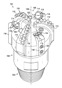
elements and cutting structures typically form a wellbore in a subterranean
formation by
shearing, crushing, cracking, or a combination of shearing, crushing, and
cracking portions of the
formation during rotation of the drill bit.
SUMMARY
[0002a] In accordance with a general aspect, there is provided a hybrid drill
bit,
comprising: a bit body defining a central bit body axis; a blade on the bit
body extending from an
end of the bit body, the blade comprising a plurality of fixed cutting
elements; and a roller disc
rotatably coupled to the bit body about the end of the bit body to rotate on a
roller disc axis, the
roller disc axis extending toward the central bit body axis, wherein the
roller disc comprises only
one cutting row that is configured to extend further into a formation in a
shoulder zone of a
corresponding bit profile than the fixed cutting elements of the blade are
configured to extend
into the formation in the shoulder zone.
[0002b] In accordance with another aspect, there is provided a well drilling
system,
comprising: a well head; a drill string connected to the well head; a hybrid
drill bit connected to
the drill string, the hybrid drill bit comprising: a bit body having a central
bit body axis at a
center of the bit body; a blade on the bit body extending from an end of the
bit body, the blade
comprising a plurality of fixed cutting elements; and a roller disc rotatably
coupled to the bit
body about the end of the bit body to rotate on a roller disc axis, the roller
disc axis extending
toward the central bit body axis, wherein the roller disc comprises only one
cutting row that is
1
CA 2943799 2018-11-02
configured to extend further into a formation in a shoulder zone of a
corresponding bit profile
than the fixed cutting elements of the blade are configured to extend into the
formation in the
shoulder zone.
[0002c] In accordance with a further aspect, there is provided a method of
cutting a
formation in a wellbore, the method comprising: rotating a drill bit in a
formation in a wellbore;
crushing or cracking the formation in a rotating action using a roller disc on
the drill bit; and
scraping the formation in a shearing action using fixed cutting elements on a
blade on the drill
bit, wherein the roller disc comprises only one cutting row that extends
further into the formation
in a shoulder zone of a corresponding bit profile than the fixed cutting
elements of the blade
extend into the formation in the shoulder zone.
DESCRIPTION OF DRAWINGS
[0003] FIG. 1 is a schematic partially cross-sectional view of an example well
system.
[0004] FIG. 2 is a schematic perspective view of an example hybrid drill bit.
[0005] FIG. 3A is a schematic end view of an example hybrid drill bit.
[0006] FIG. 3B is a schematic side view of an example hybrid drill bit
profile.
[0007] FIG. 4A is a schematic end view of an example hybrid drill bit.
[0008] FIG. 48 is a schematic side view of an example hybrid drill bit
profile.
[0009] FIG. 5A is a schematic end view of an example hybrid drill bit.
[0010] FIG. 5B is a schematic side view of an example hybrid drill bit
profile.
[0011] FIG. 6 is a schematic partially cross-sectional side view of an example
roller disc.
[0012] FIG. 7 is a schematic partially cross-sectional side view of an example
roller disc.
[0013] Like reference symbols in the various drawings indicate like elements.
la
CA 2943799 2018-11-02
CA 02943799 2016-09-23
WO 2015/178908
PCT/US2014/039114
DETAILED DESCRIPTION
[0014] Referring first to FIG. 1, a well system 10 generally includes a
substantially cylindrical wellbore 12 that extends from a wellhead 14 at the
surface 16
downward into the Earth into one or more subterranean zones of interest 18
(one shown).
The subterranean zone 18 can correspond to a single formation, a portion of a
formation,
or more than one formation accessed by the well system 10, and a given well
system 10
can access one, or more than one, subterranean zone 18. A portion of the
wellbore 12
extending from the wellhead 14 to the subterranean zone 18 is lined with
lengths of
tubing, called casing 20. The depicted well system 10 is a vertical well, with
the wellbore
12 extending substantially vertically from the surface 16 to the subterranean
zone 18.
The concepts herein, however, are applicable to many other different
configurations of
wells, including horizontal, slanted or otherwise deviated wells, and
multilateral wells
with legs deviating from an entry well.
[0015] A drill string 22 is shown as having been lowered from the surface 16
into
the wellbore 12. In some instances, the drill string 22 is a series of jointed
lengths of
tubing coupled together end-to-end and/or a continuous (i.e., not jointed)
coiled tubing.
The drill string 22 includes one or more well tools, including a bottom hole
assembly 24.
The bottom hole assembly 24 can include, for example, a hybrid drill bit. In
the example
shown, the wellbore 12 is being drilled. The wellbore 12 can be drilled in
stages, and the
casing 20 may be installed between stages.
[0016] Referring to FIG. 2, an example hybrid drill bit 100 that can be used
in the
bottom hole assembly 24 of the well system 10 of FIG. 1 is shown in a
perspective view.
The example hybrid drill bit 100 includes a bit body 102 with a pin end 104 on
one
longitudinal end of the bit body 102, a drill end 106 on another longitudinal
end of the bit
body 102 opposite the pin end 104, and a center longitudinal axis through the
center of
the bit body 102 that defines a central bit body axis 108. In some instances,
the pin end
104 is male and is threaded to mate with a female box at a tubing end of a
drill string.
The hybrid drill bit 100 includes blades 110 with fixed cutting elements 112,
the blades
110 extending longitudinally from the drill end 106 of the bit body 102, and
roller discs
114 rotatably coupled to arms 116 extending generally along the central bit
body axis 108
2
CA 02943799 2016-09-23
WO 2015/178908
PCT/US2014/039114
and beyond the drill end 106 of the bit body 102. Each of the roller discs 114
rotate
about a rotational axis that defines a roller disc axis 118 extending toward
(directly or
substantially) the central bit body axis 108. The hybrid drill bit 100 has
more than one
type of cutting structure and/or cutting element, for example, blades 110 with
fixed
cutting elements 112 and roller discs 114 configured to rotate, such that the
example drill
bit 100 is considered a hybrid drill bit.
[0017] Various types of cutting elements and cutting structures may be
provided
on a hybrid drill bit. In the example shown in FIG. 2, the hybrid drill bit
100 includes
three blades 110 and three roller discs 114. The example hybrid drill bit 100
can include
additional or different features and components. For example, the number of
roller discs
114 and blades 110 can vary. In some instances, a hybrid drill bit can have
one or more
discs and one or more blades. For example, a hybrid drill bit can have one
blade and one
roller disc, one blade and a plurality of roller discs, a plurality of blades
and one roller
disc, or a plurality of blades and a plurality of roller discs.
[0018] The arms 116 attach to the bit body 102 with fasteners 120 such that
the
arms 116 are removable from the bit body 102. In some instances, the arms 116
are an
extension of the bit body 102, are welded to the bit body 102, and/or the arms
116 are
connected to the bit body 102 in another way. In other instances, the roller
discs 114 are
rotatably coupled to the bit body 102 about the drill end. For example, the
roller discs
114 can attach to the bit body 102 about the drill end 106 without arms 116.
[0019] In some instances, the roller discs 114 rotate on spindles (not shown)
extending from the bit body 102 or arms 116 along the roller disc axes 118.
The roller
discs 114 can attach to the spindles via a bearing system to allow rotation of
the roller
discs 114 about the roller disc axes 118. The bearing system can include, for
example, a
seal, ball bearings, a lubrication system, and/or a pressure compensation
system.
[0020] The roller discs 114 can operate at a number of positions and
configurations. In the example shown, the roller discs 114 are radially
disposed near an
outer lateral periphery of the drill end 106. In some instances, the roller
discs 114 are
disposed more inward toward the central bit body axis 108, more outward from
the
central bit body axis 108, or in a different position than shown in FIG. 2. In
some
3
CA 02943799 2016-09-23
WO 2015/178908
PCT/US2014/039114
instances, the roller disc axes 118 of the roller discs 114 intersect the
central bit body axis
108, for example, to allow true rolling of the roller discs 114 against a rock
formation as
the example hybrid drill bit 100 rotates about its central bit body axis 108.
True rolling
occurs when the roller disc axes 118 intersect the central bit body axis 108,
and a radial
vector of each roller disc 114 points in the direction of rotation of the
drill bit. In other
instances, the roller disc axes 118 of the roller discs 114 do not intersect
the central bit
body axis 108, and the roller disc axes 118 are non-radial from the central
bit body axis
108. The roller discs 114 can approximate true rolling, for example, near-true
rolling
with some shearing against a formation as the example hybrid drill bit 100
rotates about
.. its central bit body axis 108. Near-true rolling occurs when the roller
disc axes 118 do
not intersect the central bit body axis 108, and a radial vector of each
roller disc 114
points slightly offset the direction of rotation of the bit body 102, for
example, when the
roller disc axis 118 is slightly offset from the central bit body axis 108.
The slight offset
causes the roller disc 114 to rotate with some skidding (i.e. shearing)
against the
formation. In certain instances, a hybrid drill bit can have at least two
roller discs, where
a first roller disc has a roller disc axis that intersects a central bit body
axis, and a second
roller disc has a roller disc axis that does not intersect the central bit
body axis.
[0021] In the example shown in FIG. 2, the blades 110 are disposed extending
substantially linearly on the drill end 106 from the central bit body axis 108
toward the
outer lateral periphery of the drill end 106. The outer lateral periphery of
the drill end
106 has a radiused edge, and the blades 110 curve longitudinally along the
radiused edge
of the outer lateral periphery of the drill end 106. The fixed cutting
elements 112 extend
in a row along the blade, such that the fixed cutting elements form a line
along each blade
110 from an end of the blade 110 closest to the central bit body axis 108 to
an end of the
.. blade 110 closest to the outer lateral periphery of the drill end 106. In
some instances,
the blades 110 and fixed cutting elements 112 are disposed in a different way.
For
example, the blades 110 can extend in a lateral curve from the central bit
body axis 108
toward the outer lateral periphery, the fixed cutting elements 112 can extend
in a curved
row along the blades 110, and/or the fixed cutting elements 112 can be
disposed in
multiple rows along each of the blades 110. In the example shown, the three
blades 110
4
CA 02943799 2016-09-23
WO 2015/178908
PCT/US2014/039114
are the same in shape and size. In other instances, one or more of the blades
on a hybrid
drill bit are a different shape or size from each other. The fixed cutting
elements 112 are
shown as being cylindrical polycrystalline diamond compact (PDC) cutters
partially
embedded into the blade 110. In some instances, the fixed cutting elements are
different,
for example, natural diamond inserts, thermally stable PDC cutters, tungsten
carbide
inserts, metal inserts, milled cutters or teeth, or another hard and abrasive
material.
[0022] In some instances, the bit body 102 includes nozzles 122 at the drill
end
106 to provide drilling fluid to the hybrid drill bit 100 during drilling.
[0023] Referring to FIG. 3A, the example hybrid drill bit 100 is shown in an
end
view, specifically, showing the drill end 106. The roller disc axes 118 of the
roller discs
114 extend toward the central bit body axis 108. Each roller disc 114 is
positioned with a
pin angle defined by the angle between the roller disc axis 118 and a plane
perpendicular
to the central bit body axis 108.
[0024] In the example shown in FIG. 3A, the roller disc axes 118 are non-
radial
from the central bit body axis 108. If non-radial, an offset, S, between each
roller disc
axis 118 and the central bit body axis 108 is less than or equal to 0.5 inches
in a 10.5 inch
size or smaller hybrid bit. For example, the offset S can be 1/16 inch, 1/14
inch, 1/2 inch,
or another dimension. The offset S is the shortest distance between the
central bit body
axis 108 and the roller disc axis 118. In other words, the offset S can be
defined as a
distance between the roller disc axis 118 and a plane through the central bit
body axis
108, where the plane is parallel to the roller disc axis 118. In some
instances, the offset S
is the same for each roller disc 114. In other instances, the offset S is
different for one or
more or each roller discs 114.
[0025] In some instances, the offset S is small such that while the hybrid
drill bit
100 rotates about the central bit body axis 108 and the drill end 106 is
against a
formation, the roller discs 114 rotate in near-true rolling with a small
amount of shear or
skidding relative to rolling. In instances with a small offset S, the near-
true rolling with a
small amount of shear or skid facilitates drilling into a formation, for
example, in drilling
into a soft formation. In other instances, the offset S is zero such that as
the hybrid drill
.. bit 100 rotates about a central bit body axis 108 and the drill end 106 is
against a
5
CA 02943799 2016-09-23
WO 2015/178908
PCT/US2014/039114
formation, the roller discs 114 rotate in true-rolling without shear against
the formation.
In instances with a zero offset S, the true-rolling of the roller discs 114
facilitates drilling
into a formation, for example, in directional drilling and drilling into a
hard formation.
[0026] Referring to FIG. 6, roller disc 114 is shown in a side view on arm
116.
The roller disc 114 includes a disc body 602 and a generally ring-shaped
cutting row 604
radially disposed about the disc body 602. The roller disc 114 includes one
cutting row
604. The cutting row 604 defines a rotational plane 606 through the center of
the cutting
row, where the roller disc axis 118 is normal to the rotational plane 606. The
center 608
of the roller disc 114 is the intersection of the roller disc axis 118 and the
rotational plane
606.
[0027] The cutting row 604 can take many forms. In some instances, the cutting
row 604 includes a continuous carbide disc radially disposed on the disc body
602. In the
example shown in FIG. 6, a cross section of the cutting row 604 is a linear
protrusion
with a substantially circular outer tip. In some instances, the cross section
of the cutting
row is a triangular protrusion with a sharp tip, a trapezoidal protrusion with
a straight tip,
a rectangular protrusion with a straight tip, a domed protrusion with a blunt
tip, a
combination of these, or another configuration. For example, a configuration
of the
cross-section can be determined by a specific rock formation type. In other
instances, the
cutting row 604 includes a discontinuous disc configuration. For example, the
cutting
row can include a plurality of diamond inserts disposed about the disc body
602. The
diamond inserts can be partially embedded into the disc body 602, coupled to
the disc
body 602 through welding, with fasteners, or bonded, and/or otherwise disposed
about
the disc body 602.
[0028] The pin angle of the roller disc 114 is defined by the angle between
the
roller disc axis 118 and a plane perpendicular to the central bit body axis
108. The pin
angle is a complement to an angle 13 between the roller disc axis 118 and a
longitudinal
axis 109. The angle p is the smallest angle between the roller disc axis 118
and the
longitudinal axis 109, where the longitudinal axis 109 is parallel to the
central bit body
axis 108 of the bit body 102 and intersects the center 608 of the roller disc
114. In the
example shown in FIG. 6, the angle 3 is about 60 degrees. The angle p can be
different,
6
CA 02943799 2016-09-23
WO 2015/178908
PCT/US2014/039114
for example, 13 can be 0 degrees, 90 degrees, an angle between 0 and 90
degrees, or
another angle.
[0029] Referring to FIG. 7, an example roller disc 114' is shown in a side
view.
The example roller disc 114' is like the roller disc 114 of FIG. 6, but the
example roller
disc 114' is oriented differently on the arm 116 than example roller disc 114.
For
example, roller disc 114' has an angle 3 of about 90 degrees.
[0030] Referring back to FIG. 3A, fixed placement of the roller discs 114 on
the
bit body 102 can vary between each of the roller discs 114. The roller discs
114 are at a
distance L from the central bit body axis 108. The distance L is the shortest
distance
between the roller disc center 608 and the central bit body axis 108. In some
instances,
the distance L can be the same for each roller disc 114. In other instances,
the distance L
is different for one or more or each roller disc 114.
[0031] FIG. 3B shows an example hybrid drill bit profile 200 corresponding to
the
example hybrid drill bit 100 of FIG. 3A. The example hybrid drill bit profile
200
includes the shape cut by the hybrid drill bit 100 of FIG. 3A, showing each
associated
cutting element of the bit 100 transposed on a plane. In the example shown in
FIG. 3B,
the hybrid drill bit profile 200 is defined by three roller discs 114a, 114b,
and 114c, and
the fixed cutting elements 112 of the blades 110 projected onto a vertical
plane passing
through the central bit body axis 108 of the bit body 102. Each roller disc
114a, 114b,
and 114c can include components and features of the roller disc 114 shown in
FIG. 6,
including a disc body 602, a cutting row 604, a rotational plane 606, a roller
disc center
608, and a longitudinal axis 109 that intersects the center of the roller disc
114 and is
parallel to the central bit body axis 108 of the bit body 102.
[0032] Each roller disc 114a, 114b, and 114c has a roller disc axis 118a,
118b,
and 118c, respectively, that is offset from the central bit body axis 108 at
distances Sa,
Sb, and Sc, respectively. Distances Sa, Sb, and Sc are fixed, but can be
different. For
example, distances Sa, Sb, and Sc can all be the same, two or more can be the
same, or
each can be different. In some instances, the offset is the same for each
roller disc 114a,
114b, and 114c, in that distances Sa, Sb, and Sc are equal.
7
CA 02943799 2016-09-23
WO 2015/178908
PCT/US2014/039114
[0033] Each roller disc 114a, 114b, and 114c is at a distance La, Lb, and Lc,
respectively, from the central bit body axis 108. Distances La, Lb, and Lc are
fixed, but
can be different. For example, distances La, Lb, and Lc can all be the same,
two or more
can be the same, or each can be different.
[0034] Each roller disc axis 118a, 118b, 118c is at a respective pin angle
from a
plane perpendicular to the central bit body axis 108. Thus, each roller disc
axis 118a,
118b, 118c is at an angle 13a, (3b, and I3c, respectively, from a longitudinal
axis 109a,
109b, 109c, respectively, that is parallel to the central bit body axis 108
and intersects the
roller disc centers 608a, 608b, 608c, respectively. Angles f3a,13b, and (3c
are fixed angles,
but can be different. For example, angles Pa, {3b, and I3c can all be the
same, two or more
angles can be the same, or each angle can be different.
[0035] In the example hybrid bit profile 200 shown in FIG. 3B, each respective
rotational plane 606a, 606b, 606c through the roller discs 114a, 114b, 114c is
perpendicular (precisely or substantially) to a periphery of the example
hybrid bit profile
200. For example, each respective rotational plane 606a, 606b, 606c can be at
an angle
between 80 degrees and 100 degrees from the periphery of the example profile
200. In
other instances, the rotational planes 606a, 606b, 606c are not generally
perpendicular to
the profile 200. The example profile 200 illustrates the cutting rows 604a,
604b, 604c of
the roller discs 114a, 114b, 114c engaging a shoulder zone of the example
profile 200. In
some instances, the cutting rows 604a, 604b, 604c engage a cone zone, a nose
zone, a
gage zone, and/or the shoulder zone. The cutting rows 604a, 604b, 604c of the
roller
discs 114a, 114b, 114c do not engage a cone zone of the example profile 200.
The gage
zone is associated with the cylindrical sidewall of a wellbore, such that
engaging the gage
zone includes cutting only the cylindrical sidewall of the wellbore. The
shoulder zone,
nose zone, and cone zone are associated with a downhole end of the wellbore
(i.e. bottom
of hole). The nose zone extends farther beyond the drill end of a bit body
than the cone
and shoulder zones, and the shoulder zone bridges the nose zone and the gage
zone. The
cone zone is in the lateral center of the drill bit on the longitudinal drill
end.
[0036] The cutting rows 604a, 604b, 604c extend further in the profile 200
than
the fixed cutting elements 112 of the blades 110. The cutting rows 604a, 604b,
604c lead
8
CA 02943799 2016-09-23
WO 2015/178908
PCT/US2014/039114
the fixed cutting elements 112 of the blades 110 in cutting a formation such
that the
cutting rows 604a, 604b, 604c prefracture the formation during drilling. The
blades 110
can also support the roller discs 114a, 114b, 114c during drilling by limiting
the contact
stress between the cutting rows 604a, 604b, 604c and the formation. For
example, the
fixed cutting elements 112 contact the formation as the cutting rows 604a,
604b, 604c are
partially engaged into the formation. In some instances, one or more of the
fixed cutting
elements 112 of the blades 110 extends further in the profile 200 than the
cutting rows
604a, 604b, 604c. In other instances, the cutting rows 604a, 604b, 604c and
the fixed
cutting elements 112 extend into the profile 200 evenly. In other instances,
one or more
fixed cutting elements 112 can extend further than one or more of the cutting
rows 604a,
604b, 604c, and another subset of cutting rows 604a, 604b, 604c can extend
further than
other fixed cutting elements 112. For example, a cutting row profile of a
first roller disc
can extend further than a fixed cutting element profile, and the fixed cutting
element
profile can extend further than a profile of a second roller disc.
[0037] Referring to FIG. 4A, an example hybrid drill bit 100' is shown in an
end
view. The example hybrid drill bit 100' is like the example hybrid drill bit
100 of FIG.
3A, except the hybrid drill bit 100' includes four roller discs 114 and two
blades 110.
[0038] FIG. 4B shows an example hybrid drill bit profile 200' corresponding to
the example hybrid drill bit 100' of FIG. 4A. The example hybrid drill bit
profile 200' is
like the example hybrid drill bit profile 200 of FIG. 3B, except the example
hybrid drill
bit profile 200' includes four roller discs 114a, 114b, 114c, and 114d, and
fixed cutting
elements 112 from two blades 110.
[0039] Referring to FIG. 5A, an example hybrid drill bit 100" is shown in an
end
view. The example hybrid drill bit 100" is like the example hybrid drill bit
100 of FIG.
.. 3A, except the hybrid drill bit 100" includes four roller discs 114 and
three blades 110'.
The blades 110' of the example hybrid drill bit 100" radially extend from the
central bit
body axis 108 less than the roller discs 114. For example, the blades 110' are
more
radially inward than the roller discs 114 with respect to the central bit body
axis 108 of
the bit body 102.
9
CA 02943799 2016-09-23
WO 2015/178908
PCT/US2014/039114
[0040] FIG. 5B shows an example hybrid drill bit profile 200¨ corresponding to
the example hybrid drill bit 100" of FIG. 5A. The example hybrid drill bit
profile 200"
is like the example hybrid drill bit profile 200 of FIG. 3B, except the
example hybrid drill
bit profile 200" includes four roller discs 114a, 114b, 114c, 114d and fixed
cutting
elements 112 from the three blades 110 from FIG. 5A.
[0041] Hybrid drill bits, such as the example hybrid drill bits 100, 100', and
100", can be configured to rotate about a central bit body axis with a drill
end against a
formation in a wellbore. Roller discs disposed about the drill end crush or
crack a
formation in a substantially or wholly rotating action, while fixed cutting
elements on a
blade scrape against the formation in a shearing action. The rotating action
of the roller
discs can include true rolling or near-true rolling with partial scraping or
shearing of the
formation. In some instances, the roller discs prefracture the formation such
that the
fixed cutting elements scrape the prefractured cuttings of formation.
[0042] In view of the discussion above, certain aspects encompass, a hybrid
drill
bit including a bit body having a central bit body axis at a center of the bit
body, a blade
on the bit body extending from an end of the bit body, and a roller disc
rotatably coupled
to the bit body about the end of the bit body to rotate on a roller disc axis.
The roller disc
axis extends toward the central bit body axis. The blade includes a plurality
of fixed
cutting elements.
[0043] Certain aspects encompass, a well drilling system including a well
head, a
drill string connected to the well head, and a hybrid drill bit connected to
the drill string.
The hybrid drill bit includes a bit body having a central bit body axis at a
center of the bit
body, a blade on the bit body extending from an end of the bit body, and a
roller disc
rotatably coupled to the bit body about the end of the bit body to rotate on a
roller disc
axis. The roller disc axis extends toward the central bit body axis. The blade
includes a
plurality of fixed cutting elements.
[0044] Certain aspects encompass, a method of cutting a formation in a
wellbore.
The method includes rotating a drill bit in a formation in a wellbore,
crushing or cracking
the formation in a rotating action using a roller disc on the drill bit, and
scraping the
formation in a shearing action using fixed cutting elements on a blade on the
drill bit.
CA 02943799 2016-09-23
WO 2015/178908
PCT/US2014/039114
[0045] The aspects above can include some, none, or all of the following
features.
The hybrid drill bit includes an arm coupled to the bit body extending
generally along the
central bit body axis and beyond the end of the bit body. The roller disc is
rotatably
coupled to the arm. The roller disc axis of the roller disc intersects the
central bit body
axis. The roller disc axis of the roller disc is non-radial from the central
bit body axis.
The shortest distance S between the central bit body axis and the roller disc
axis is less
than 0.5 inches. The roller disc includes a disc body and a generally ring-
shaped cutting
row radially disposed about the disc body, and the roller disc includes only
one cutting
row. The cutting row defines a rotational plane through the center of the
cutting row, and
the rotational plane is normal to the roller disc axis. The rotational plane
of the roller disc
is generally perpendicular to a periphery of a corresponding bit profile, and
a center of
the roller disc is the intersection of the roller disc axis and the rotational
plane. The roller
disc is in a shoulder zone of the bit profile. The hybrid bit includes a
plurality of discs
and a plurality of blades. The plurality of discs is a different distance L
from the central
bit body axis, where the distance L is the shortest distance between a center
of the
respective roller disc and the central bit body axis. The plurality of roller
discs may not
be in the cone zone of a corresponding bit profile. Each roller disc axis of
the plurality of
discs is at a different angle 13 from the central bit body axis, where the
angle 13 is the angle
of the respective roller disc axis from the central bit body axis. The
plurality of blades
are more radially inward than the plurality of discs with respect to the
central bit body
axis of the bit body. The cutting row of the roller disc extends further from
the end of the
bit body than the fixed cutting elements of the blade. The hybrid drill bit
includes an arm
coupled to the bit body extending generally along the central bit body axis
and beyond
the end of the bit body, and the roller disc is rotatably coupled to the arm.
The roller disc
includes a disc body and a generally ring-shaped cutting row radially disposed
about the
disc body, and the roller disc comprises only one cutting row. Crushing or
cracking the
formation in a rotating action using a roller disc includes prefracturing the
formation
using the roller disc, where the roller disc is deeper into the formation than
the fixed
cutting elements of the blade. Scraping the formation in a shearing action
using fixed
cutting elements on a blade includes scraping prefractured cuttings of
formation.
11
CA 02943799 2016-09-23
WO 2015/178908
PCT/US2014/039114
Crushing or cracking the formation in a rotating action using a roller disc on
the drill bit
includes a roller disc configured to roll against the formation with small
shear.
[0046] A number of embodiments have been described. Nevertheless, it will be
understood that various modifications may be made. Accordingly, other
embodiments
are within the scope of the following claims.
12