Note: Descriptions are shown in the official language in which they were submitted.
SADDLE RIDING TYPE VEHICLE WITH TWO FRONT WHEELS AND LOCKABLE
LINKAGE
BACKGROUND OF THE INVENTION
1. Field of the Invention
[1) The present invention relates to saddle riding type
vehicles and more particularly to a saddle riding type vehicle
including a pair of front wheels.
2. Description of the Related Art
[2] An example of a saddle riding type vehicle is a three-
wheeled vehicle including a pair of front wheels and a linkage
that connects the pair of front wheels to a vehicle body frame.
The three-wheeled vehicle is able to turn while leaning by the
operation of the linkage.
[3] JP 2005-313876 A discloses an anti-roll device for a
three-wheeled vehicle. The anti-roll device includes a brake
disk provided integrally with one element of the linkage and a
caliper attached to a vehicle body frame. In the anti-roll
device, the caliper is used to fix the brake disk to the vehicle
body frame. In this way, the operation of the linkage is
prevented. This prevents a rolling motion of the vehicle.
- 1 -
CA 2943813 2018-02-15
CA 02943813 2016-09-23
. ,
,
[4] JP 2009-286266 A discloses a saddle riding type
vehicle. The saddle riding type vehicle includes a support, a
lock, a sensor, and a controller. The support supports a pair of
wheels so that the wheels are able move up and down relative to
the vehicle body. The lock connects to the support to prevent
the movement of the pair of wheels in the vertical direction.
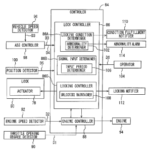
The sensor detects the state of the vehicle. The controller
controls the lock based on a detection result from the sensor.
The vertical movement of the pair of wheels is automatically
prevented or allowed by the controller. Therefore, the operation
of the support is prevented quickly when a prescribed condition
is established.
[51 However, when the operation of the support is
automatically controlled, the rider's intention cannot
completely be taken into account. For example, the operation of
the support may be prevented against the rider's intention. The
condition in which the operation of the support is prevented
must be set appropriately in order to avoid this inconvenience.
This may however complicate the way of setting the condition or
the like.
SUMMARY OF THE INVENTION
[6] Preferred embodiments of the present invention provide
- 2 -
CA 02943813 2016-09-23
a saddle riding type vehicle that is able to quickly prevent the
operation of a linkage upon fulfillment of a prescribed
condition in accordance with the rider's intention.
[7] A saddle riding type vehicle according to a first
preferred embodiment of the present invention includes a vehicle
body frame, a pair of front wheels, a linkage, a lock, a
controller, and an operator. The linkage connects the pair of
front wheels to the vehicle body frame. The lock locks the
linkage by preventing operation of the linkage and unlocks the
linkage by allowing the linkage to operate. The controller is
configured or programmed to control locking and unlocking of the
linkage by the lock. The operator continues to output an
operation signal to the controller while operation by the rider
is input. The controller controls the lock to lock the linkage
if a locking condition that allows the linkage to be locked is
fulfilled when the operation signal is input.
[8] The operator is provided so that the rider's intention
is readily and accurately reflected in the control and operation
of the vehicle. If the locking condition is already established
when the rider operates the operator, the linkage is switched to
its locked state from its unlocked state in response to the
rider's operation of the operator. The operation signal
continues to be output while the operator is being operated.
- 3 -
CA 02943813 2016-09-23
. .
,
Therefore, if the rider has operated the operator before the
locking condition is fulfilled (or the locking condition is not
yet established when the rider operates the operator), the
linkage is switched quickly from its unlocked state to its
locked state when the locking condition is fulfilled.
[9] According to a preferred embodiment of the present
invention, the controller is configured or programmed to keep
the linkage in an unlocked state via the lock if the operation
signal input upon the present fulfillment of the locking
condition has continuously been input since the previous
fulfillment of the locking condition.
[10] Accordingly, the rider is able to be urged to stop
operating the operator after the linkage is locked. The rider's
intention is more easily and accurately reflected in the control
and operation of the vehicle.
[11] According to a preferred embodiment of the present
invention, the saddle riding type vehicle further includes a
locking notifier that notifies the rider that the linkage is
locked by the lock.
[12] Accordingly, the rider is made aware of the locked
state of the linkage. A way of notifying the rider of the locked
state of the linkage includes, for example, to provide an
indication using a visual indicator or an audio indicator using
- 4 -
CA 02943813 2016-09-23
a speaker.
[13] The saddle riding type vehicle according to a
preferred embodiment of the present invention further includes a
condition fulfillment notifier that notifies the rider of
fulfillment of the locking condition.
[14] Accordingly, the rider is made aware of fulfillment of
the locking condition. Therefore, if, for example, the operator
has not been operated before fulfillment of the locking
condition, the rider is notified to operate the operator at the
appropriate time.
[15] According to a preferred embodiment of the present
invention, the saddle riding type vehicle further includes a
detector that detects a vehicle state. The controller is
configured or programmed to include a locking condition
determiner, a signal input determiner, and a locking controller.
The locking condition determiner determines whether the locking
condition is fulfilled based on the vehicle state detected by
the detector. The signal input determiner determines whether the
operation signal is input while the locking condition is
fulfilled. The locking controller is configured or programmed to
control the lock to lock the linkage if the operation signal is
input while the locking condition is fulfilled.
[16] According to a preferred embodiment of the present
- 5 -
CA 02943813 2016-09-23
invention, the saddle riding type vehicle further includes an
abnormality determiner. The abnormality determiner determines
whether the detector has an abnormality. The locking condition
determiner does not determine whether the locking condition is
fulfilled if the detector has an abnormality.
[17] Accordingly, the fulfillment of the locking condition
is more accurately determined.
[18] According to a preferred embodiment of the present
invention, the signal input determiner includes an input period
determiner. The input period determiner determines whether the
operation signal input upon the present fulfillment of the
locking condition has continuously been input since the previous
fulfillment of the locking condition. The locking controller is
configured or programmed to include an unlocking maintainer that
keeps the linkage in an unlocked state via the lock if the
operation signal input upon the present fulfillment of the
locking condition has continuously been input since the previous
fulfillment of the locking condition.
[19] According to a preferred embodiment of the present
invention, the saddle riding type vehicle further includes a
plurality of the detectors. The locking condition determiner
determines whether the locking condition is fulfilled based on
vehicle states detected by the plurality of detectors.
- 6 -
CA 02943813 2016-09-23
[20] Accordingly, the precision of detecting the vehicle
states improves.
[21] According to a preferred embodiment of the present
invention, the plurality of detectors include a state detector
that detects a state of the linkage, a throttle opening degree
detector that detects a throttle opening degree, and a vehicle
speed detector that detects a vehicle speed.
[22] According to a preferred embodiment of the present
invention, the plurality of detectors further include an engine
speed detector that detects an engine speed.
[23] According to a preferred embodiment of the present
invention, the plurality of detectors further include a vehicle
speed change rate detector that detects a vehicle speed change
rate.
[24] According to a preferred embodiment of the present
invention, the vehicle speed change rate detector outputs a
difference between a vehicle speed detected by the vehicle speed
detector at a first time point and a vehicle speed detected by
the vehicle speed detector at a second time point as the vehicle
speed change rate.
[25] Accordingly, a vehicle speed change rate is obtained
more easily than the case of obtaining it by differentiating a
vehicle speed.
- 7 -
CA 02943813 2016-09-23
[26] According to a preferred embodiment of the present
invention, the saddle riding type vehicle further includes a
damper. The damper damps vibrations in opposite phases generated
in the pair of front wheels. The lock locks the linkage by
preventing operation of the damper and unlocks the linkage by
allowing the damper to operate.
[27] Accordingly, an additional lock is not necessary.
Therefore, a compact saddle riding type vehicle is achieved.
[28] The above and other elements, features, steps,
characteristics and advantages of the present invention will
become more apparent from the following detailed description of
the preferred embodiments with reference to the attached
drawings.
BRIEF DESCRIPTION OF THE DRAWINGS
[29] Fig. 1 is a left side view of a general structure of a
saddle riding type vehicle according to a preferred embodiment
of the present invention.
[30] Fig. 2 is a front view of a general structure of a
linkage.
[31] Fig. 3 is a diagram of a hydraulic circuit for a
damper.
[32] Fig. 4 is a block diagram for illustrating signals
- 8 -
CA 02943813 2016-09-23
input/output to/from a controller.
[33] Fig. 5 is a flowchart for illustrating locking control
by a lock controller.
[34] Fig. 6 is a timing chart for an operation signal input
before fulfillment of a locking condition when a linkage is
locked.
[35] Fig. 7 is a timing chart for an operation signal input
after fulfillment of a locking condition when the linkage is
locked.
[36] Fig. 8 is a timing chart showing how an operation
signal input upon the present fulfillment of the locking
condition has continued to be input since the previous
fulfillment of the locking condition.
[37] Fig. 9 is a timing chart showing how an operation
signal input upon the present fulfillment of the locking
condition has not continued to be input since the previous
fulfillment of the locking condition.
DETAILED DESCRIPTION OF THE PREFERRED EMBODIMENTS
[38] Now, saddle riding type vehicles according to
preferred embodiments of the present invention will be described
in conjunction with the accompanying drawings in which the same
or corresponding portions are designated by the same reference
- 9 -
CA 02943813 2016-09-23
k .
,
i
characters and their description will not be repeated. Note that
the saddle riding type vehicle may be a scooter type vehicle,
for example.
[39] Fig. 1 is a left side view of a general structure of a
saddle riding type vehicle 10 according to a preferred
embodiment of the present invention. Fig. 2 is a front view of a
general structure of a linkage provided in the saddle riding
type vehicle 10. In the following description, the front, back,
left, and right refer to these positions as seen by the rider
seated on a seat 32 of the saddle riding type vehicle 10. In Fig.
1, the arrow F indicates a forward direction of the saddle
riding type vehicle 10 and the arrow U indicates an upward
direction of the saddle riding type vehicle 10. In Fig. 2, the
arrow L indicates a leftward direction of the saddle riding type
vehicle 10 and the arrow U indicates the upward direction of the
saddle riding type vehicle 10.
[40] As shown in Figs. 1 and 2, the saddle riding type
vehicle 10 includes a vehicle body frame 12, a pair of front
wheels 14L and 14R, and a rear wheel 16.
[41] As shown in Fig. 1, the vehicle body frame 12 is
covered with a vehicle cover 18. As shown in Fig. 1, the vehicle
body frame 12 includes a head pipe 20.
[42] As shown in Fig. 1, the head pipe 20 is provided at a
- 10 -
CA 02943813 2016-09-23
front portion of the vehicle body frame 12. As shown in Figs. 1
and 2, the head pipe 20 includes a steering shaft 26 inserted
therethrough. As shown in Figs. 1 and 2, the steering shaft 26
includes a handle 28 at its upper end.
[43] As shown in Fig. 1, a front wheel support 30 is
provided in front of the head pipe 20. As shown in Fig. 2, the
front wheel support 30 supports the pair of front wheels 14L and
14R. The front wheel support 30 will be described in detail
below.
[44] As shown in Fig. 1, the rear wheel 16 is provided
below the seat 32. The seat 32 is provided above the vehicle
body frame 12. The driving force of an engine 94 (see Fig. 5) is
transmitted to rotate the rear wheel 16.
[45] Referring to Fig. 2, the front wheel support 30 will
be described. The front wheel support 30 includes a linkage 36,
a suspension 38, and a damper 40.
[46] The linkage 36 connects the pair of front wheels 14L
and 14R to the vehicle body frame 12 (for example, to a front
frame provided in front of the head pipe 20). The linkage 36
includes an upper left arm 42L, an upper right arm 42R, a lower
left arm 44L, a lower right arm 44R, a left knuckle arm 46L, and
a right knuckle arm 46R.
[471 One of the upper left arm 42L and the upper right arm
- 11 -
CA 02943813 2016-09-23
42R is able to swing relative to the other around an axial line
through a swing center that extends in the front-back direction
of the vehicle. The lower left arm 44L is provided under the
upper left arm 42L. The lower right arm 44R is provided under
the upper right arm 42R. One of the lower left arm 44L and the
lower right arm 44R is able to swing relative to the other
around an axial line through a swing center that extends in the
front-back direction of the vehicle.
[48] The left knuckle arm 46L extends in the vertical
direction of the vehicle to connect a left end of the upper left
arm 42L and a left end of the lower left arm 44L. The left
knuckle arm 46L is able to swing relative to the upper left arm
42L and the lower left arm 44L around an axial line through a
swing center that extends in the front-back direction of the
vehicle. Therefore, the left knuckle arm 46L is able to move in
the vertical direction.
[49] The right knuckle arm 46R extends in the vertical
direction of the vehicle to connect a right end of the upper
right arm 42R and a right end of the lower right arm 44R. The
right knuckle arm 46R is able to swing relative to the upper
right arm 42R and the lower right arm 44R around an axial line
through a swing center that extends in the front-back direction
of the vehicle. Therefore, the right knuckle arm 46R is able to
- 12 -
CA 02943813 2016-09-23
move in the vertical direction.
[50] At a lower end of the left knuckle arm 46L, a front
wheel support member 52L is able to swing around an axial line
through a swing center that extends in the vertical direction of
the vehicle. The front wheel support member 52L supports the
front wheel 14L in a rotatable manner.
[51] At a lower end of the right knuckle arm 46R, a front
wheel support member 52R is able to swing around an axial line
through a swing center that extends in the vertical direction of
the vehicle. The front wheel support member 52R supports the
front wheel 14R in a rotatable manner.
[52] The front wheel support members 52L and 52R rotate in
a plan view as the handle 28 is operated. In this way, the
saddle riding type vehicle 10 is able to turn to the left and
right.
[53] As shown in Fig. 2, the suspension 38 is connected to
the linkage 36. The suspension 38 includes a cylinder 54 and a
piston 56.
[54] The cylinder 54 is attached to a right end of the
upper right arm 42R through a bracket 60. Here, the bracket 60
is fixed to the upper right arm 42R. The cylinder 54 is able to
swing relative to the bracket 60. Therefore, the cylinder 54 is
able to swing relative to the upper right arm 42R. The cylinder
- 13 -
CA 02943813 2016-09-23
,
54 stores operating oil.
[551 The piston 56 is attached to a left end of the upper
left arm 42L through a bracket 58. Here, the bracket 58 is fixed
to the upper left arm 42L. The piston 56 is able to swing
relative to the bracket 58. Therefore, the piston 56 is able to
swing relative to the upper left arm 42L.
[56] The piston 56 is able to move in an axial direction of
the cylinder 54. The piston 56 includes a main body (not shown)
provided inside the cylinder 54. Upon receiving a vibration
input that may change the relative position between the upper
left arm 42L and the upper right arm 42R, the piston 56
advances/withdraws within the cylinder 54 to move in the axial
direction of the cylinder 54. At that time, the movement of the
main body of the piston 56 in the cylinder 54 produces a damping
force. As a result, displacement vibrations in the linkage 36
are damped. For example, when vibrations in the same phase are
generated in the upper left arm 42L and the upper right arm 42R,
in other words, when vibrations in the same phase are generated
in the pair of front wheels 14L and 14R, the vibrations are
damped by the suspension 38.
[57] As shown in Fig. 2, the damper 40 is attached to the
linkage 36. The damper 40 includes a piston 62 and a cylinder 64.
The piston 62 is attached to the lower left arm 44L in a
- 14 -
CA 02943813 2016-09-23
swingable manner. The cylinder 64 is attached to the upper right
arm 42R in a swingable manner.
[58] Referring to Fig. 3, a hydraulic circuit that controls
the operation of the damper 40 will be described. Fig. 3 is a
diagram of the hydraulic circuit for the damper 40.
[59] The piston 62 includes a piston main body 62A and a
piston rod 62B. The piston main body 62A is located in a center
portion in an axial direction of the piston rod 62B. The piston
main body 62A is able to move in the cylinder 64. The piston rod
62B extends through the cylinder 64 in the axial direction. More
specifically, the damper 40 is preferably a so-called through-
rod damper, for example.
[60] The cylinder 64 stores operating oil. The inside of
the cylinder 64 is partitioned into two spaces (a first space
66A and a second space 66B) by the piston main body 62A. The
first and second spaces 66A and 66B are connected to each other
by a damping circuit 68. The operating oil is able to therefore
move between the first and second spaces 66A and 66B through the
damping circuit 68.
[61] The damping circuit 68 includes four flow paths 70A,
70B, 70C, and 70D, two flow regulators 72A and 72B, and one
temperature compensating chamber 74. The flow regulator 72A is
connected to the first space 66A through the flow path 70A. The
- 15 -
CA 02943813 2016-09-23
flow regulator 72A is connected to the flow regulator 72B
through the flow path 70B. The flow regulator 72B is connected
to the second space 66B through the flow path 700. The
temperature compensating chamber 74 is connected to the flow
path 703 through the flow path 70D.
[62] The flow regulators 72A and 723 each include a valve
element and a spring. The valve elements are positioned to block
the flow paths in the flow regulators 72A and 723 by the
energizing force of the springs. This prevents the operating oil
from flowing in the damping circuit 66. In other words, the
operation of the damper 40 is prevented. The prevention of the
operation of the damper 40 prevents the operation of the linkage
36. More specifically, the linkage 36 attains a locked state.
[63] An actuator 78 is, for example, a motor. The actuator
78 moves the valve element against the energizing force of the
spring. At that time, the valve elements are in such a position
that they do not block the flow paths in the flow regulators 72A
and 72B. Therefore, the operating oil is allowed to flow in the
damping circuit 66. In other words, the damper 40 is allowed to
operate. When the operation of the damper 40 is thus allowed,
vibrations are damped. When, for example, vibrations in opposite
phases are generated in the lower left aim 44L and the upper
right arm 42R, or when vibrations in opposite phases are
- 16 -
CA 02943813 2016-09-23
generated in the pair of front wheels 14L and 14R, the
vibrations are damped by the damper 40. When the operation of
the damper 40 is allowed, the operation of the linkage 36 is
allowed. In other words, the linkage attains an unlocked state.
[64] As can be clearly understood from the above
description, the damper 40, the damping circuit 66, and the
actuator 78 define the lock 80.
[65] Note that, in the example shown in Fig. 3, a relief
valve 82 is arranged in parallel to the flow regulator 72A. The
relief valve 82 prevents the internal pressure of the cylinder
64 from increasing when the operation of the damper 40 is
prevented.
[66] Referring to Fig. 4, a controller 84 provided in the
saddle riding type vehicle 10 will be described. Fig. 4 is a
block diagram for illustrating signals input/output to/from the
controller 84.
[67] The controller 84 includes a lock controller 86 and an
engine controller 88.
[68] The lock controller 86 is configured or programmed to
control locking and unlocking of the linkage 36 by the lock 80.
The lock controller 86 is configured or programmed to include a
locking condition determiner 86A, a signal input determiner 86B,
and a locking controller 86C.
- 17 -
CA 02943813 2016-09-23
,
[69] The locking condition determiner 86A determines
whether a prescribed locking condition is fulfilled based on a
throttle opening degree signal D1, an engine speed signal D2, a
vehicle speed signal D3, a vehicle speed change rate signal D4,
and a position signal D5. The locking condition will be
described below.
[70] The throttle opening degree signal D1 is output by a
throttle opening degree detector 90 and represents a throttle
opening degree. The throttle opening degree signal D1 is input
to the lock controller 86 through the engine controller 88.
[71] The engine speed signal D2 is output by an engine
speed detector 92 and represents the speed of the engine 94. The
engine speed signal D2 is input to the lock controller 86
through the engine controller 88.
[72] The vehicle speed signal D3 is output by a vehicle
speed detector 96 and represents a vehicle speed. The vehicle
speed detector 96 includes, for example, a wheel speed sensor.
According to the present preferred embodiment, the saddle riding
type vehicle 10 includes an ABS (anti-lock braking system).
Therefore, the vehicle speed signal D3 is input to the lock
controller 86 through an ABS controller 98 that controls the
operation of the ABS.
[73] The vehicle speed change rate signal D4 is output by
- 18 -
CA 02943813 2016-09-23
,
the ABS controller 98 and represents a vehicle speed change rate.
More specifically, according to the present preferred embodiment,
the ABS controller 98 defines a vehicle speed change rate
detector.
[74] The vehicle speed change rate may be, for example, a
derivative value of a vehicle speed detected by the vehicle
speed detector 96, i.e., an acceleration of the vehicle or the
difference between vehicle speeds detected by the vehicle speed
detector 96 at a first time point and a second time point (which
occurs later than the first time point). If the vehicle speed
change rate is obtained as the difference between vehicle speeds
at first and second time points, an amount of computation
required to obtain a vehicle speed change rate is reduced as
compared to the case of obtaining a derivative value of a
vehicle speed as a vehicle speed change rate.
[75] The position signal D5 is output by a position
detector 100 and represents the position of the valve elements
provided in the flow regulators 72A and 72B. The position
detector 100 determines whether the linkage 36 is locked. In
short, the position detector 100 defines a state detector that
detects the state of the linkage 36. When the valve elements are
positioned to block the flow paths in the flow regulators 72A
and 72B, the position detector 100 outputs a locked position
- 19 -
CA 02943813 2016-09-23
signal D5 as the position signal D5. When the valve elements are
positioned so that the flow paths in the flow regulators 72A and
72B are not blocked, the position detector 100 outputs an
unlocked position signal D5 as the position signal D5. The
position signal D5 is input to the lock controller 86. The
position detector 100 detects the position of the valve elements
included in the flow regulators 72A and 72B, for example, by
directly detecting the position of these valve elements or by
detecting the position of the actuator 78 as well as voltage
that drives the actuator 78.
[76] The locking condition determiner 86A includes an
abnormality determiner 102. The abnormality determiner 102
determines whether an abnormality has occurred at detectors that
detect the state of the vehicle, i.e., at the throttle opening
degree detector 90, the engine speed detector 92, the vehicle
speed detector 96, the position detector 100, and the ABS
controller 98 that defines the vehicle speed change rate
detector.
[77] If any of the throttle opening degree detector 90, the
engine speed detector 92, the vehicle speed detector 96, the
position detector 100, and the ABS controller 98 that serves as
the vehicle speed change rate detector has an abnormality, an
abnormality alarm 114 included in the saddle riding type vehicle
- 20 -
CA 02943813 2016-09-23
informs or warns the rider about the abnormality. The warning
from the abnormality alarm 114 continues until the abnormality
is removed. The warning from the abnormality alarm 114 may be
anything that is visibly or audibly recognized by the rider. The
warning that is visibly recognizable by the rider may be made,
for example, using a visual indicator. The indicator is, for
example, located in a meter arranged near the handle 28. The
warning that is audibly recognizable by the rider may be made
using a speaker. The speaker is, for example, located in the
meter arranged near the handle 28.
[78] If the locking condition is fulfilled, the rider is
notified of the fulfillment of the locking condition by a
condition fulfillment notifier 110 provided in the saddle riding
type vehicle 10. The notification by the condition fulfillment
notifier 110 may continue, for example, until the linkage 36
attains a locked state or for a prescribed time period after the
locking condition is fulfilled. The notification by the locking
condition fulfillment notifier 110 may be anything that is
visually or audibly recognizable by the rider similarly to the
alarm from the abnormality alarm 114.
[79] The signal input determiner 86B determines whether an
operation signal is input while the locking condition is
fulfilled. A result of determination by the locking condition
- 21 -
CA 02943813 2016-09-23
,
,
determiner 86A and an operation signal 1)6 input to the lock
controller 86 are used to make the determination.
[80] The operation signal 1)6 is output by an operator 104.
The operator 104 continues to output the operation signal 1)6 to
the lock controller 86 when the rider carries out an operation.
The operation signal 1)6 may be output continuously or
intermittently. The operator 104 is positioned so that the rider
is able to operate the operator while driving. The operator 104
includes, for example, an operation switch provided on the
handle 28.
[81] The signal input determiner 86B includes an input
period determiner 106. The input period determiner 106
determines whether the operation signal D6 input upon the
present fulfillment of the locking condition has continued since
the previous fulfillment of the locking condition.
[82] The locking controller 86C is configured or programmed
to control the lock 80 to lock the linkage 36 if the operation
signal 1)6 is input while the locking condition is fulfilled. A
result of determination by the signal input determiner 86B is
used to determine whether the operation signal D6 is input while
the locking condition is fulfilled. According to the present
preferred embodiment, the locking controller 86C is configured
or programmed to control the lock 80 if the operation signal 1)6
- 22 -
CA 02943813 2016-09-23
a
input upon the present fulfillment of locking condition has not
continued since the previous fulfillment of the locking
condition. More specifically, the locking controller 86C drives
the actuator 78 to move the valve elements included in the flow
regulators 72A and 72B. In this way, the valve elements block
the flow paths in the flow regulators 72A and 72B. As a result,
the linkage 36 attains a locked state.
[83] The locking controller 86C unlocks the linkage 36 if a
prescribed unlocking condition is fulfilled. The unlocking
condition may be, for example, the rider's operation of an
unlocking switch or a failure of fulfillment of the locking
condition. The unlocking switch may be, for example, the
operator 104.
[84] A locking notifier 112 included in the saddle riding
type vehicle 10 notifies the rider of a locked state of the
linkage 36. The notification by the locking notifier 112
continues, for example, until the vehicle stops. The
notification by the locking notifier 112 may be anything that is
visibly or audibly recognizable by the rider similarly to the
alarm from the abnormality alarm 114 or the notification by the
condition fulfillment notifier 110.
[85] The locking controller 86C includes an unlocking
maintainer 108. The unlocking maintainer 108 maintains an
- 23 -
CA 02943813 2016-09-23
' .
unlocked state of the linkage 36 by the lock 80 if the operation
signal D6 input upon the present fulfillment of the locking
condition has continued since the previous fulfillment of the
locking condition.
[86] Now, control carried out by the lock controller 86 to
lock the linkage 36 (locking control by the lock controller 86)
will be described.
[87] The lock controller 86 is configured or programmed to
control the lock 80 to lock the linkage 36 if the operation
signal D6 has been input upon fulfillment of a locking condition
under which the linkage 36 can be locked. For example, the
locking condition is fulfilled if all of the following
conditions 1 to 5 are satisfied.
Condition 1: The linkage 36 is in an unlocked state.
Condition 2: The present throttle opening degree is zero.
_
Condition 3: The present engine speed is lower than a
prescribed engine speed.
Condition 4: The present vehicle speed is lower than a
prescribed vehicle speed.
Condition 5: The present vehicle speed change rate is less
than a prescribed vehicle speed change rate.
[88] Now, referring to Fig. 5, the locking control by the
lock controller 86 will be described. Fig. 5 is a flowchart for
- 24 -
CA 02943813 2016-09-23
illustrating the locking control by the lock controller 86.
[89] First, the lock controller 86 (the abnormality
determiner 102 to be specific) determines in step Si whether an
abnormality has occurred at the throttle opening degree detector
90, the engine speed detector 92, the vehicle speed detector 96,
the position detector 100, and the ABS controller 98 as the
vehicle speed change rate detector. The abnormality determiner
102 determines whether an abnormality has occurred based on
signals input to the lock controller 86, in other words, based
on outputs from the detectors 90, 92, 96, 100, and 98. More
specifically, it is determined that an abnormality has occurred
if outputs from the detectors 90, 92, 96, 100, and 98 are
outside predetermined ranges or outputs from the detectors 90,
92, 96, 100, and 98 or do not change despite a control carried
out to change these outputs.
[90] If an abnormality has occurred (YES in step S1), the
lock controller 86 outputs an alarm in step S7 about the ongoing
abnormality. More specifically, the abnormality determiner 102
outputs an alarm about the abnormality through the abnormality
alarm 114. Then, the lock controller 86 ends the locking control.
[91] On the other hand, if an abnormality has not occurred
(NO in step S1), the lock controller 86 determines the state of
the vehicle in step S2. More specifically, the locking condition
- 25 -
CA 02943813 2016-09-23
determiner 86A determines if the above-described conditions 1 to
are all satisfied.
[92] The locking condition determiner 86A determines
whether the linkage 36 is in an unlocked state by referring to
an input position signal D5. If the unlocked position signal D5
is input, the condition 1 is satisfied.
[93] The locking condition determiner 86A determines
whether the present throttle opening degree is zero by referring
to an input throttle opening degree signal Dl. If the throttle
opening degree is zero, in other words, if the throttle valve is
closed, the condition 2 is satisfied.
[94] The locking condition determiner 86A determines
whether the present engine speed is lower than a prescribed
engine speed (about 2500 rpm, for example) by referring to an
input engine speed signal 132. Here, the prescribed engine speed
is an engine speed at which the driving force of the engine is
transmitted to the rear wheel 16 through a CVT (continuously
variable transmission). If the present engine speed is lower
than the prescribed engine speed, the condition 3 is satisfied.
For example, the vehicle starts to move on a downward slope if
the throttle is fully closed. Therefore, the vehicle state is
preferably determined based on a condition other than the
vehicle speed. Therefore, it is determined whether the condition
- 26 -
CA 02943813 2016-09-23
,
3 is satisfied.
[95] The locking condition deteiminer 86A determines
whether the present vehicle speed is lower than a prescribed
vehicle speed (about 10 km/h, for example) by referring to an
input vehicle speed signal D3. If the present vehicle speed is
lower than the prescribed vehicle speed, the condition 4 is
satisfied.
[96] The locking condition determiner 86A determines
whether the present vehicle speed change rate is less than a
prescribed vehicle speed change rate (about 15%, for example) by
referring to an input vehicle speed change rate signal D4. If
the present vehicle speed change rate is less than the
prescribed vehicle speed change rate, the condition 5 is
satisfied. For example, if the throttle is fully closed, the
vehicle speed change rate increases when the vehicle travels on
a downward slope. It is determined if the condition 5 is
satisfied so that the linkage 36 is not locked in such a case.
For example, the average vehicle speed is calculated at
intervals of several ms, for example, and if the difference
between an immediately previously calculated average vehicle
speed and the present calculated average speed is about 1 km/h,
for example, and the state has not continued for about 100 ms,
for example, it is determined that the present vehicle speed
- 27 -
CA 02943813 2016-09-23
change rate is less than the prescribed vehicle speed change
rate.
[97] Unless at least one of the conditions 1 to 5 is
satisfied, the lock controller 86 ends the locking control. On
the other hand, if all of the conditions 1 to 5 are satisfied,
the lock controller 86 notifies the rider of fulfillment of the
locking condition in step S3. More specifically, the locking
condition controller 68A notifies the rider of the fulfilment of
the locking condition through the condition fulfillment notifier
110.
[98] The lock controller 86 subsequently determines in step
S4 whether the rider intends to lock the linkage 36. More
specifically, the signal input determiner 86B determines whether
an input condition is fulfilled. For example, the input
condition is fulfilled when the following conditions 6 and 7 are
both satisfied.
Condition 6: The operation signal D6 is input.
Condition 7: The operation signal D6 input upon the present
fulfillment of the locking condition has not continued since the
previous fulfillment of the locking condition.
[99] The signal input determiner 86B determines whether the
operation signal D6 is input. If the operation signal D6 is
input, the condition 6 is satisfied.
- 28 -
CA 02943813 2016-09-23
[100] The operation signal D6 may be input before or after
fulfillment of the locking condition as shown in Fig. 6 or Fig.
7. Note that in Figs. 6 and 7, the linkage 36 attains a locked
state when the locking condition is fulfilled. This indicates
that the operation to lock the linkage 36 starts when the
locking condition is fulfilled. In Figs. 6 and 7, the linkage 36
is in an unlocked state when the locking condition is
unfulfilled. This indicates that the operation to unlock the
linkage 36 starts when the locking condition is unfulfilled.
[101] The signal input determiner 86B (the input period
determiner 106 to be specific) determines whether the operation
signal D6 input upon the present fulfillment of the locking
condition has continued since the previous fulfillment of the
locking condition. As shown in Fig. 8, if the operation signal
D6 input upon the present fulfillment of the locking condition
has not continued since the previous fulfillment of the locking
condition, the condition 7 is satisfied. On the other hand, as
shown in Fig. 9, if the operation signal D6 input upon the
present fulfillment of the locking condition has continued since
the previous fulfillment of the locking condition, the condition
7 is not satisfied. In Figs. 8 and 9, the linkage 36 is locked
when the locking condition is fulfilled. This indicates that the
operation to lock the linkage 36 starts when the locking
- 29 -
CA 02943813 2016-09-23
condition is fulfilled. As shown in Figs. 8 and 9, the linkage
36 is unlocked when the locking condition is unfulfilled. This
shows that the operation to unlock the linkage 36 starts when
the locking condition is unfulfilled.
[102] If one of the conditions 6 and 7 is not satisfied, the
lock controller 86 ends the locking control. On the other hand,
if the conditions 6 and 7 are both satisfied, the lock
controller 86 locks the linkage 36 in step S5. More specifically,
the locking controller 86C drives the actuator 78 to lock the
linkage 36.
[103] The lock controller 86 subsequently notifies the rider
of the locked state of the linkage 36 in step S6. More
specifically, the locking controller 86C notifies the rider of
the locked state of the linkage 36 through the locking notifier
112. Then, the lock controller 86 ends the locking control.
[104] The saddle riding type vehicle 10 includes the vehicle
body frame 12, the pair of front wheels 14L and 14R, the linkage
36, the lock 80, the lock controller 86, and the operator 104.
The linkage 36 connects the pair of front wheels 14L and 14R to
the vehicle body frame 12. The lock 80 locks the linkage 36 by
preventing the operation of the linkage 36 and unlocks the
linkage 36 by allowing the linkage 36 to operate. The lock
controller 86 is configured or programmed to control locking and
- 30 -
CA 02943813 2016-09-23
. 1
,
,
unlocking of the linkage 36 by the lock 80. The operator 104
continues to output the operation signal D6 to the lock
controller 86 while the operation by the rider is input. The
lock controller 86 controls the lock 80 to lock the linkage 36
if the operation signal D6 is input when the locking condition
that allows the linkage 36 to be locked is fulfilled.
[105] Since the operator 104 is provided, the intention of
the rider is easily achieved. If the locking condition is
fulfilled when the rider operates the operator 104, the rider is
able to switch the linkage 36 from its unlocked state to its
locked state by operating the operator 104. The operation signal
D6 continues to be output while the operator 104 is operated.
Therefore, if the rider operates the operator 104 before
fulfillment of the locking condition (or when the locking
condition is yet to be fulfilled), the linkage 36 is changed
quickly from its unlocked state to its locked state once the
locking condition is fulfilled.
[106] In the saddle riding type vehicle 10, the lock
controller 86 maintains the unlocked state of the linkage 36 by
the lock 80 if the operation signal D6 input upon the present
fulfillment of the locking condition has continued since the
previous fulfillment of the locking condition. The rider is
urged to stop operating the operator 104 after the linkage 36 is
- 31 -
CA 02943813 2016-09-23
. ,
locked. This makes it easier to take into account and to perform
control of the vehicle in accordance with the rider's intention.
[107] The saddle riding type vehicle 10 further includes the
locking notifier 112. The locking notifier 112 notifies that the
linkage 36 is locked by the lock 80. In this way, the rider is
made aware of the locked state of the linkage 36.
[108] The saddle riding type vehicle 10 further includes the
condition fulfillment notifier 110. In this way, the rider is
made aware of fulfillment of the locking condition. Therefore,
if the rider does not operate the operator 104 before
fulfillment of the locking condition, the rider operates the
operator at the appropriate time.
[109] The saddle riding type vehicle 10 further includes the
abnormality determiner 102. The abnormality determiner
determines whether any of the plurality of detectors 90, 92, 96,
100, and 98 has an abnormality. If any of the detectors has an
abnormality, it is not determined whether the locking condition
is fulfilled. In this way, the locking condition is determined
more precisely.
[110] According to the above-described preferred embodiments,
the condition 2 is preferably satisfied if the present throttle
opening degree is zero, but the condition 2 may be satisfied if
the present throttle opening degree is less or not more than a
- 32 -
CA 02943813 2016-09-23
prescribed throttle opening degree. Alternatively, the condition
2 may be satisfied if the average throttle opening degree for a
prescribed time period is less or not more than a prescribed
engine speed.
[111] According to the above-described preferred embodiments,
the condition 3 is preferably satisfied if the present engine
speed is less than a prescribed engine speed but the condition 3
may be fulfilled if the present engine speed is not more than
the prescribed engine speed. Alternatively, the condition 3 may
be satisfied if the engine speed is less than or not more than
the prescribed engine speed for a prescribed time period. The
condition 3 may be satisfied if the average engine speed for a
prescribed time period is less or not more than the prescribed
average engine speed.
[112] According to the above-described preferred embodiments,
the condition 4 is preferably satisfied if the present vehicle
speed is lower than a prescribed vehicle speed, but the
condition 4 may be satisfied if the present vehicle speed is not
more than the prescribed vehicle speed. Alternatively, the
condition 4 may be satisfied if the vehicle speed is lower or
not more than the prescribed vehicle speed for a prescribed time
period or the condition 4 may be satisfied if the average
vehicle speed for a prescribed period is lower or not more than
- 33 -
CA 02943813 2016-09-23
the prescribed average vehicle speed.
[113] According to the above-described preferred embodiments,
the condition 5 is preferably satisfied if the present vehicle
speed change rate is less than a prescribed vehicle speed change
rate, but the condition 5 may be satisfied if the present
vehicle speed change rate is not more than the prescribed
vehicle speed change rate. Alternatively, the condition 5 may be
satisfied if the vehicle speed change rate is less or not more
than the prescribed vehicle change rate for a prescribed time
period or if the average vehicle speed change rate for a
prescribed time period is less or not more than the prescribed
vehicle speed change rate.
[114] According to the above-described preferred embodiments,
the locking condition is preferably fulfilled if all of the
conditions 1 to 5 are satisfied, but the locking condition may
be fulfilled if, for example, all of the conditions 1, 2, and 4
are satisfied.
[115] According to the above-described preferred embodiments,
the lock controller 86 preferably is configured or programmed to
include the input period determiner 106 and the unlocking
maintainer 108 but the lock controller 86 does not have to
include these elements. More specifically, the input condition
may be established if only the condition 6 is satisfied.
- 34 -
CA 02943813 2016-09-23
[116] According to the above-described preferred embodiments,
the vehicle speed signal D3 is preferably input to the lock
controller 86 through the ABS controller 98 but the vehicle
speed signal D3 may be input to the lock controller 86 not
through the ABS controller 98.
[117] According to the above-described preferred embodiments,
the saddle riding type vehicle 10 preferably includes the
condition fulfillment notifier 110 and the locking notifier 112
but the saddle riding type vehicle 10 does not have to include
these elements.
[118] While preferred embodiments of the present invention
have been described above, it is to be understood that
variations and modifications will be apparent to those skilled
in the art without departing from the scope and spirit of the
present invention. The scope of the present invention, therefore,
is to be determined solely by the following claims.
- 35 -