Note: Descriptions are shown in the official language in which they were submitted.
VEHICLE
=
CROSS REFERENCE TO RELATED APPLICATION
This application claims the benefit of JP Patent Application No.
2015-194214 filed September 30, 2015.
BACKGROUND OF THE INVENTION
1. Field of the Invention
[0001] The present invention relates to a vehicle including a
body frame that is able to lean and two front wheels that are
aligned side by side in a left-and-right direction.
2. Description of the Related Art
[0002] International Patent Publication No. WO/2014/046282 Al
describes a vehicle including a body frame that is able to lean and
two wheels that are aligned in a left-and-right direction. This
vehicle includes a linkage. The linkage includes an upper cross
member and a lower cross member. In addition, the linkage also
includes a right side member that is connected to right portions of
the upper cross member and the lower cross member, and a left side
member that is connected to left portions of the upper cross member
and the lower cross member. Middle portions of the upper cross
member and the lower cross member are supported on the body frame.
The upper cross member and the lower cross member are supported on
the body frame so as to turn about axes that extend substantially in
a front-and-rear direction of the body frame.
[0003] The upper cross member and the lower cross member turn
relative to the body frame as the body frame leans, such that a
relative position between the two front wheels in an up-and-down
direction of the body frame changes. The upper cross member and the
lower cross member are provided above the two front wheels in the
up-and-down direction of the body frame in such a state that the
1
\
CA 2943838 2018-03-15
vehicle is standing upright.
[0004] This linkage supports the right front wheel and the left
front wheel so as to move in the up-and-down direction of the bOdy
frame. The linkage supports the right front wheel so as to turn
about a right steering axis that extends in the up-and-down
direction of the body frame and supports the left front wheel so as
to turn about a left steering axis that is parallel to the right
steering axis.
[0005] The vehicle includes a handlebar, a steering shaft and a
tie-rod. The handlebar is fixed to the steering shaft. The steering
shaft is supported so as to turn relative to the body frame. When
the handlebar is turned, the steering shaft is also turned. The tie-
rod transmits a turning motion of the steering shaft to the right
front wheel and the left front wheel to turn the right front wheel
about the right steering axis and turn the left front wheel about
the left steering axis.
[0006] In the vehicle described in International Patent
Publication No. WO/2014/046282 Al, the handlebar turns about an
axis that extends in the up-and-down direction of the body frame,
and the upper cross member and the lower cross member of the linkage
turn about the axes that extend in the front-and-rear direction of
the body frame. Due to this, the handlebar is disposed above the
linkage so as to avoid interference with the linkage.
[0007] When attempting to develop a vehicle having a larger
engine displacement than that of the vehicle described in
International Patent Publication No, WO/2014/046202 Al, greater
rigidity is required of the linkage, and this enlarges the linkage
in size, such that the handlebar position is eventually raised.
Alternatively, when attempting to develop a vehicle having a larger
maximum banking angle than that of the vehicle described
International Patent Publication No. WO/2014/046282 Al, the movable
range of the linkage is enlarged, such that the handlebar position
is eventually raised.
=
2
CA 2943838 2018-03-15
[0008] However, the handlebar needs to be provided in a position
where a rider sitting on the seat is able to extend his or her arms
to reach it, and therefore, it becomes difficult to freely set the
handlebar position.
SUMMARY OF THE PRESENT INVENTION
[0009] The inventor'of preferred embodiments of the present
invention considered the possibility of enhancing the degree of
freedom in setting the handlebar position in order to enhance the
usability of the handlebar by the rider by providing the handlebar
in a low position where the rider is able to easily extend his or
her arms to reach the handlebar.
[0010] In the vehicle described in International Patent
Publication No. WO/2014/046282 Al, a steering force that is
inputted into the handlebar is transmitted to the tie-rod by the
single steering shaft. Then, the inventor of preferred embodiments
of the present invention considered a construction in which a
steering shaft is divided into two shafts that are connected to each
other, so that a steering force inputted into a handlebar is
transmitted to a tie-rod by a mechanism having the two shafts.
[0011] Then, compared with the vehicle described in
International Patent Publication No. WO/2014/046282 Al, in the
vehicle in which the steering force is transmitted to the tie-rod by
a mechanism including two shafts, there are concerns that the
vehicle is enlarged in size because a connector is added to connect
the two shafts in addition to the one shaft.
[0012] Further, when attempting to mount on this vehicle a
steering lock that locks the right front wheel and the left front
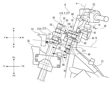
3
CA 2943838 2018-03-15
CA. 02943838 2016-09-30
wheel so as not to be steered or turned and a steering stopper that
restricts the maximum steering angle of the right front wheel and
the left front wheel, this may require a further enlargement in the
size of the vehicle.
[0013] Accordingly, preferred embodiments of the present
invention provide a vehicle including a steering lock and a steering
stopper without the risk of enlarging the size of the vehicle while
enhancing the usability of the handlebar by the rider.
[0014] According to a preferred embodiment of the present
invention, a vehicle includes a body frame that is able to lean to
the right of the vehicle when the vehicle turns right and is able
to lean to the left of the vehicle when the vehicle turns left; a
right front wheel and a left front wheel that are aligned side by
side in a left-and-right direction of the body frame; a linkage that
includes a cross member that turns about a link axis that extends
in a front-and-rear direction of the body frame relative to the body
frame, which supports the right front wheel and the left front wheel
so as to be displaced relatively in an up-and-down direction of the
body frame, and which supports the right front wheel so as to turn
about a right steering axis that extends in the up-and-down direction
of the body frame and supports the left front wheel so as to turn
about a left steering axis that is parallel to the right steering
axis; and a steering force transmission that includes a steering
force input that is disposed between the right steering axis and the
left steering axis when seen from the front of the vehicle and which
is provided so as to turn about a middle steering axis that is parallel
to the right steering axis and which transmits a steering force that
is inputted into the steering force input to the right front wheel
and the left front wheel, wherein the steering force transmission
includes a rear shaft into which a steering force is inputted from
the steering force input and which is able to turn about a rear axis;
4
CA 02943838 2016-09-30
a front shaft that is disposed ahead of the rear shaft in relation
to the front-and-rear direction of the body frame and which is able
to turn about a front axis; a connector that transmits the turning
of the rear shaft to the front shaft; a steering lock that includes
a first portion and a second portion that are able to be displaced
relative to each other and which makes it impossible for the first
portion to be displaced relative to the second portion to make it
impossible for the right front wheel and the left front wheel to be
steered; and a steering stopper that includes a third portion and
a fourth portion that are able to be displaced relative to each other
and which stops the relative displacement of the third portion to
the fourth portion so as to prevent the right front wheel and the
left front wheel from being steered to more than a maximum steering
angle to restrict the maximum steering angle of the right front wheel
and the left front wheel; wherein along the link axis of the cross
member, a distance between the front shaft and the cross member is
smaller than a distance between the rear shaft and the cross member,
when seen from a side of the vehicle that is standing upright and
is not steered at all, a distance between the front shaft and the
right steering axis is smaller than a distance between the rear shaft
and the right steering axis, when seen from the side of the vehicle
that is standing upright and is not steered at all, a distance between
the rear shaft and the middle steering axis is smaller than a distance
between the front shaft and the middle steering axis, in the steering
lock and the steering stopper, the first portion and the third portion
are provided on a member that is displaced together with the rear
shaft when the rear shaft turns or are on the rear shaft, and the
second portion and the fourth portion are provided on a member that
is displaced relative to the rear shaft portion when the rear shaft
turns.
[00151 In a
preferred embodiment of the present invention, the
CA 02943838 2016-09-30
steering force transmission that transmits the steering force to the
right front wheel and the left front wheel that is inputted into the
steering force input includes the rear shaft into which the steering
force is inputted from the steering force input, the front shaft and
the connector that connects the front shaft and the rear shaft
together. Due to this, compared with the case where the steering force
that is inputted into the steering force input is transmitted to the
right front wheel and the left front wheel by a single steering shaft,
the degree of freedom in designing the arrangement of the steering
force input is high. Due to this, the steering force input is able
to be disposed in a position or posture that enables a rider to use
the steering force input easily to enhance the usability by the rider.
[0016] Further, the vehicle is prevented from being enlarged in
size for the following reason. A certain degree of rigidity is
required of the steering lock and the steering stop. High rigidity
is required of the steering lock so as to handle an external force
that is exerted on the right front wheel, the left front wheel or
the steering force input in such a state that the steering lock locks
the right front wheel and the left front wheel so as not to be steered.
In addition, high rigidity is also required of a member on which the
steering lock is mounted.
[0017] Similarly, high rigidity is required of the steering
stopper so as to handle an external force that is exerted on the right
front wheel, the left front wheel and the steering force input in
an attempt to increase further the steering angle of the right front
wheel and the left front wheel in such a state that the steering
stopper restricts the steering angle of the right front wheel and
the left front wheel after the right front wheel and the left front
wheel are steered to the maximum steering angle. In
addition, high
rigidity is also required of a member on which the steering stopper
is mounted.
6
CA 02943838 2016-09-30
[0018] Due to this, different from preferred embodiments of the
present invention, in a case where the steering lock is provided on
the rear shaft, while the steering stopper is provided on the front
shaft, the rigidity of both the rear shaft and the front shaft needs
to be increased. Due to this, a large diameter member needs to be
used for both the rear shaft and the front shaft, resulting in an
enlargement in the size of the vehicle.
[0019] Then, in case the steering lock and the steering stopper
are provided on either of the front shaft and the rear shaft of the
steering force transmission, only the rigidity of either of the front
shaft and the rear shaft needs to be ensured. Due to this, the steering
force transmission is compact, compared with the case where the
steering lock is provided on either of the front shaft and the rear
shaft of the steering force transmission and the steering stopper
is provided on the other of the front shaft and the rear shaft of
the steering force transmission.
[0020] Then, the inventor of preferred embodiments of the present
invention considered that both the steering lock and the steering
stopper are provided on either of the front shaft and the rear shaft
of the steering force transmission. Firstly, the inventor of
preferred embodiments of the present invention studied providing the
steering lock and the steering stopper on the front shaft.
[0021] In a preferred embodiment of the present invention, along
the link axis of the cross member, the distance between the front
shaft and the cross member is smaller than the distance between the
rear shaft and the cross member. Namely, the cross member is
provided in a position that is located closer to the front shaft than
the rear shaft. Since the cross member receives an impact force from
a road surface, the cross member is a thick member, and hence, the
cross member has a high rigidity. Due to this, it is considered
reasonable to provide the steering lock and the steering stopper by
7
CA 02943838 2016-09-30
using the cross member around the front shaft or the highly rigid
member that supports the cross member.
[0022] However, the inventor of preferred embodiments of the
present invention noticed that the cross member is relatively large
to secure the high rigidity and that the movable range of the large
cross member is also enlarged. Additionally, since rigidity is
required of each of the steering lock and the steering stopper, the
steering lock and the steering stopper also become relatively large
in size. Namely, the inventor of preferred embodiments of the present
invention noticed that since both the members that may interfere with
each other are large in size, an attempt to provide the steering lock
and the steering stopper on a circumference of the front shaft
enlarges the size of the vehicle.
[0023] Then, the inventor of preferred embodiments of the present
invention considered the circumference of the rear shaft of the
steering force transmission. Since the rear shaft is located farther
from the linkage than the front shaft, it becomes difficult for the
rear shaft to interfere with other members. Then, the inventor of
preferred embodiments of the present invention studied providing the
steering lock and the steering stopper on the circumference of the
rear shaft.
[0024] As a result of an extended study of the rigidity required
of the rear shaft, the inventor of preferred embodiments of the
present invention noticed that the rigidity of the rear shaft and
the supporting rigidity of the rear shaft need to be set high in order
to receive a steering force that is inputted by the rider. The
steering force that is inputted by the rider includes a force
component that is inputted to turn the steering force input and a
force component that is inputted by the rider when the rider attempts
to cause the vehicle to lean in the left-and-right direction. Then,
the inventor of preferred embodiments of the present invention
8
CA 02943838 2016-09-30
noticed that, in case the steering lock and the steering stopper are
provided on the highly rigid rear shaft and the member that supports
the rear shaft with high rigidity and which is displaced relative
to the rear shaft when the rear shaft turns, a highly rigid member
does not have to be provided only for the steering lock and the
steering stopper to be mounted thereon, which makes it difficult for
the vehicle to be enlarged in size.
[0025] Then, by providing the steering lock and the steering
stopper on the member that is displaced together with the rear shaft
or the rear shaft and the member that is displaced relative to the
rear shaft when the rear shaft turns, the vehicle including the
steering lock and the steering stopper is prevented from being
enlarged in size while enhancing the usability of the vehicle by the
rider.
[0026] In a preferred embodiment of the present invention, the
body frame preferably includes a right frame and a left frame, a front
shaft support that supports the front shaft so as to turn supported
by the right frame and the left frame, and a rear shaft support that
supports the rear shaft so as to turn provided on the right frame
and the left frame behind a connecting portion that connects the right
frame and the left frame with the front shaft support in the
front-and-rear direction of the body frame.
[0027] According to the vehicle configured as described above,
the supporting rigidity of both the front shaft support and the rear
shaft support is enhanced by making use of the highly rigid body
frame.
[0028] In a preferred embodiment of the present invention, the
body frame preferably includes a front shaft support including a
pivotable support that supports the cross member so as to turn, and
the front shaft preferably penetrates the front shaft support.
[0029] According to the vehicle configured as described above,
9
CA 02943838 2016-09-30
the front support supports both the cross member and the front shaft
whose turning axes are different from each other, and therefore, the
two members are supported by one member, such that not only is the
increase in the number of parts prevented but also an enlargement
in the size of the vehicle is prevented.
[0030] In a preferred embodiment of the present invention, at
least one middle shaft is preferably provided between the front shaft
and the rear shaft, so that a steering force that is transmitted to
the rear shaft is transmitted to the front shaft via the middle shaft.
[0031] According to the vehicle configured as described above,
the degree of freedom in designing the steering force transmission
member is high, and therefore, the usability of the steering force
transmission member by the rider is enhanced further.
[0032] In a preferred embodiment of the present invention, the
rear shaft may be shorter than the front shaft.
[0033] According to the vehicle configured as described above,
the rear shaft into which the steering force applied to the steering
force input is inputted is shorter than the front shaft, and therefore,
even though an angle defined by the rear shaft relative to a vertical
direction is changed when seen from the side of the vehicle, it
becomes difficult for the rear shaft to interfere with other members.
Due to this, the steering force input is easy to be disposed in a
position or posture where the rider is able to easily use the steerina
force input.
[0034] In a preferred embodiment of the present invention, the
rear shaft may be longer than the front shaft.
[0035] According to the vehicle configured as described above,
in the event that the first portion or the second portion of the
steering lock and the .third portion and the fourth portion of the
steering stopper are attached to the long rear shaft, the area where
the rear shaft is attached is wide, and therefore, it is easy to
CA 02943838 2016-09-30
provide the steering lock and the steering stopper in the position
where interference thereof with other members is avoided. In addition,
the steering lock and the steering stopper are provided at a plurality
of locations, thus enhancing the prevention of theft.
[0036] In a preferred embodiment of the present invention, when
seen from the top of the vehicle, at least a portion of the steering
lock is preferably disposed behind the rear shaft. According to the
vehicle configured as described above, it is easy to prevent the
interference of the steering lock with the linkage.
[0037] In a preferred embodiment of the present invention, when
seen from the top of the vehicle that is standing upright and is not
steered at all, at least a portion of the connector may be disposed
either on the right or the left of the rear axis in relation to the
left-and-right direction of the body frame, and when seen from the
top of the vehicle that is standing upright and is not steered at
all, at least a portion of the steering lock may be disposed either
on the right or the left of the rear axis in relation to the
left-and-right direction of the body frame. According to the vehicle
configured as described above, it is easy to prevent the interference
of the steering lock with the connector.
[0038] In a preferred embodiment of the present invention, the
connector preferably transmits a turn motion of the rear shaft to
the front shaft by a link including at least one joint. According
to the vehicle configured as described above, in the event that the
front shaft is spaced farther away from the rear shaft to avoid the
interference of the steering lock or the steering stopper with the
linkage, in case the front shaft and the rear shaft are connected
by the long link, the connector is compact in size.
[0039] In a preferred embodiment of the present invention, the
cross member preferably includes an upper cross member and a lower
cross member that is provided below the upper cross member, the body
11
CA 02943838 2016-09-30
frame preferably includes an upper support that supports the upper
cross member so as to turn and a lower support that supports the lower
cross member so as to turn, and the front shaft preferably penetrates
the body frame so that the front shaft passes the upper support and
the lower support when seen from the front of the vehicle.
[0040] According to the vehicle configured as described above,
a portion of the body frame where the upper support and the lower
support are provided is given an enhanced rigidity in order to support
the upper cross member and the lower cross member with high rigidity.
The front shaft penetrates a portion of the body frame whose rigidity
is enhanced, and therefore, the vehicle is compact in size while
avoiding interference of the linkage with the steering force
transmission.
[0041] In particular, in the event that a portion of the body frame
where the upper support and the lower support are provided includes
a pipe-shaped member, a portion of the body frame is highly rigid
and light in weight. In case the front shaft penetrates the interior
of the pipe-shaped body frame, the vehicle is compact in size while
avoiding interference of the linkage with the steering force
transmission.
[0042] In a preferred embodiment of the present invention, the
body frame preferably includes a link support that supports the cross
member so as to turn, the cross member preferably includes a front
cross element that is disposed ahead of the link support and a rear
cross element that is disposed behind the link support, and the front
axis of the front shaft is preferably disposed between a front end
of the front cross element and a rear end of the rear cross element.
[0043] According to the vehicle configured as described above,
when the linkage is operated, the front cross element and the rear
cross element turn about the link axis that extends in the
front-and-rear direction of the body frame. Consequently, even
12
CA 02943838 2016-09-30
though the front shaft is provided between the front cross element
and the rear cross element, the front shaft does not interfere with
the front cross element and the rear cross element when the linkage
is operated. Thus, the vehicle is compact in size while preventing
the above described interference.
[0044] In a preferred embodiment of the present invention, the
body frame preferably includes a pipe-shaped link support that
supports the cross member so as to turn, the front shaft is provided
coaxially with the pipe-shaped link support, and at least a portion
of the front shaft is inserted into an interior of the pipe-shaped
link support.
[0045] According to the vehicle configured as described above,
the link support that supports the cross member so as to turn includes
the pipe-shaped member, and therefore, the link support is highly
rigid and light in weight. At least a portion of the front shaft is
inserted into the interior of the pipe-shaped link support, and
therefore, the vehicle is compact in size while the link support is
highly rigid, light in weight and avoids interference of the linkage
with the steering force transmission.
[0046] The above and other elements, features, steps,
characteristics and advantages of the present invention will become
more apparent from the following detailed description of the
preferred embodiments with reference to the attached drawings.
BRIEF DESCRIPTION OF THE DRAWINGS
[0047] Fig. 1 is a side view showing the entire vehicle according
to a preferred embodiment of the present invention as seen from a
left side thereof.
[0048] Fig. 2 is a front view showing a front portion of the
vehicle shown in Fig. 1.
[0049] Fig. 3 is a side view showing a left shock absorber and
a left front wheel.
13
CA 02943838 2016-09-30
[0050j Fig. 4 is a plan view showing the front portion of the
vehicle shown in Fig. 1.
[0051] Fig. 5 is a plan view showing the front portion of the
vehicle shown in Fig. 1 when the vehicle is steered.
[0052] Fig. 6 is a front view showing the front portion of the
vehicle shown in Fig. 1 when the vehicle is caused to lean.
[0053] Fig. 7 is a front view showing the front portion of the
vehicle shown in Fig. 1 when the vehicle is caused to lean while being
steered.
[0054] Fig. 8 is a side view showing a steering force
transmission.
[0055] Fig. 9 is a plan view showing the steering force
transmission.
[0056] Fig. 10 is a bottom view of an upstream side steering shaft.
[0057] Fig. 11 is a plan view showing schematically a link support,
a headstock, a right frame, and a left frame.
[0058] Fig. 12 is a side view showing a link support and a
downstream side steering shaft according to a first modified
preferred embodiment of the present invention.
[0059] Fig. 13 is a top view of a steering force transmission of
a vehicle according to a second modified preferred embodiment of the
present invention.
[0060] Fig. 14 is a schematic top view of a steering force
transmission of a vehicle according to a third modified preferred
embodiment of the present invention.
DETAILED DESCRIPTION OF THE PREFERRED EMBODIMENTS
[0061] Referring to the accompanying drawings, preferred
embodiments of the present invention will be described in detail
below.
[0062] In the accompanying drawings, an arrow F denotes a front
14
CA 02943838 2016-09-30
or forward direction of a vehicle. An arrow B denotes a back/rear
or backward/rearward direction of the vehicle. An arrow U denotes
an up or upward direction of the vehicle. An arrow D denotes a down
or downward direction of the vehicle. An arrow R denotes a right or
rightward direction of the vehicle. An arrow L denotes a left or
leftward direction of the vehicle.
[006.3] A vehicle turns with a body frame leaning in a
left-and-right direction of the vehicle relative to a vertical
direction. In addition to the directions based on the vehicle,
directions based on the body frame will be defined. In the
accompanying drawings, an arrow FF denotes a front or forward
direction of the body frame. An arrow FB denotes a back/rear or
backward/rearward of the body frame. An arrow FU denotes an up or
upward direction of the body frame. An arrow FD denotes a down or
downward direction of the body frame. An arrow FR denotes a right
or rightward direction of the body frame. An arrow FL denotes a left
or leftward direction of the body frame.
[0064] In this description, a "front-and-rear direction of the
body frame," a "left-and-right direction of the body frame" and an
"up-and-down direction of the body frame" means a front-and-rear
direction, a left-and-right direction and an up-and-down direction
based on the body frame as viewed from a rider who rides the vehicle.
"A side of or sideways of the body frame" means directly on the right
or left of the body frame. "A side of or sideways of the body frame"
means directly on the right or left of the body frame.
[0065] In this description, an expression reading "something
extends in the front-and-rear direction of the body frame" includes
a situation in which something extends while being inclined in
relation to the front-and-rear direction of the body frame and means
that something extends with a gradient which is closer to the
front-and-rear direction of the body frame rather than the
CA. 02943838 2016-09-30
left-and-right direction and the up-and-down direction of the body
frame.
[0066] In this description, an expression reading "something
extends in the left-and-right direction of the body frame" includes
a situation in which something extends while being inclined in
relation to the left-and-right direction of the body frame and means
that something extends with a gradient which is closer to the
left-and-right direction of the body frame rather than the
front-and-rear direction of the body frame and the up-and-down
direction of the body frame.
[0067] In this description, an expression reading "something
extends in the up-and-down direction of the body frame" includes a
situation in which something extends while being inclined in relation
to the up-and-down direction of the body frame and means that
something extends with a gradient which is closer to the up-and-down
direction of the body frame rather than the front-and-rear direction
of the body frame and the left-and-right direction of the body frame.
[0068] In this description, an expression reading the "body frame
stands upright or is in an upright state" means a state in which the
up-and-down direction of the body frame coincides with the vertical
direction in such a state that the vehicle is not steered at all.
In this state, the directions based on the vehicle and the directions
based on the vehicle frame coincide with each other. When the vehicle
is turning with the body frame caused to lean to the left or right
direction from the vertical direction, the left-and-right direction
of the vehicle does not coincide with the left-and-right direction
of the body frame. Likewise, the up-and-down direction of the
vehicle does not coincide with the up-and-down direction of the body
frame. However, the front-and-rear direction of the vehicle
coincides with the front-and-rear direction of the body frame.
[0069] In this description, "rotation or rotating" means that a
16
CA. 02943838 2016-09-30
member is displaced at an angle of 360 degrees or more about a center
axis thereof. In this description, "turning" means that a member
is displaced at an angle of less than 360 degrees about a center axis
thereof.
[0070] Referring to Figs. 1 to 7, a vehicle 1 according to
preferred embodiments of the present invention will be described.
The vehicle 1 is driven by of power generated from a power source
and which includes a body frame which is able to lean and two front
wheels which are aligned side by side in a left-and-right direction
of the body frame.
[0071] Fig. 1 is a left side view showing the entire vehicle 1
as viewed from the left thereof. The vehicle 1 includes a vehicle
main body portion 2, a pair of left and right front wheels 3, a rear
wheel 4, a linkage 5 and a steering force transmission 6.
[0072] The vehicle main body portion 2 includes a body frame 21,
a body cover 22, a seat 24 and an engine unit 25. In Fig. 1, the vehicle
1 is standing upright or is in an upright state. The following
description which will be made by reference to Fig. 1 is based on
the premise that the vehicle 1 is standing in the upright state.
[0073] The body frame 21 extends in the front-and-rear direction
of the vehicle 1. The body frame 21 includes a headstock 211 (refer
to Fig. 4: an example of a rear shaft support), a link support 212
(refer to Fig. 4: an example of a front shaft support), an engine
support 213, a left frame 91 and a right frame 92.
[0074] The headstock 211 supports an upstream side steering shaft
60, which will be described below, so as to turn. The headstock 211
extends in an up-and-down direction of the body frame 21. The link
support 212 is provided ahead of the headstock 211 in a front-and-rear
direction of the vehicle 1. The link support 212 supports the linkage
so as to turn.
[0075] The engine support 213 is provided behind the headstock
17
CA 02943838 2016-09-30
211 in the front-and-rear direction of the vehicle 1. The engine
support 213 supports the engine unit 25. The engine unit 25 supports
the rear wheel 4 so as to allow the rotation thereof. The engine unit
25 includes a power source such as an engine, an electric motor, a
battery or the like and a device such as a transmission. The power
source generates a force by which the vehicle 1 is driven.
[0076] The right frame 92 is provided on the right of the left
frame 91 in relation to a left-and-right direction of the vehicle.
The right frame 92 and the left frame 91 preferably have a laterally
symmetrical shape. The left frame 91 and the right frame 92 connect
the headstock 211, the link support 212 and the engine support 213
together.
[0077] The body cover 22 includes a front cover 221, a pair of
left and right front mudguards 223 and a rear mudguard 224. The body
cover 22 is a body portion which covers at least a portion of body
elements which are mounted on the vehicle 1 such as the pair of left
and right front wheels 3, the body frame 21, the linkage 5 and the
like.
[0078] The front cover 221 is disposed ahead of the seat 24. The
front cover 221 covers the linkage 5 and at least a portion of the
steering force transmission 6.
[0079] At least portions of the pair of left and right front
mudguards 223 are individually disposed directly below the front
cover 221. At least portions of the pair of left and right front
mudguards 223 are disposed directly above the pair of left and right
front wheels 3, respectively.
[0080] At least a portion of the rear mudguard 224 is disposed
directly above the rear wheel 4.
[0081] At least portions of the pair of left and right front wheels
3 are disposed directly below the front cover 221.
[0082] At least portion of the rear wheel 4 is disposed below the
18
CA 02943838 2016-09-30
seat 24. At least portion of the rear wheel 4 is disposed directly
below the rear fender 224.
[0083] Fig. 2 is a front view of the front portion of the vehicle
1 as viewed from the front of the body frame 21. In Fig. 2, the vehicle
1 is standing in an upright state. The following description which
will be made by reference to Fig. 2 is based on the premise that the
vehicle 1 is standing upright or in the upright state. Fig. 2 shows
the front portion of the vehicle 1 as seen through the front cover
221 that is indicated by dashed lines.
[0084] The pair of left and right front wheels 3 include a left
front wheel 31 and a right front wheel 32. The left front wheel 31
and the right front wheel 32 are aligned side by side in the
left-and-right direction of the body frame 21. The right front wheel
32 is provided on the right of the left front wheel 31 on the body
frame 21.
[0085] The vehicle 1 includes a left shock absorber 33, a right
shock absorber 34, a left bracket 317 and a right bracket 327.
[0086] Fig. 3 is a side view showing the left shock absorber 33
and the left front wheel 31. The right shock absorber 34 and the left
shock absorber 33 are preferably laterally symmetrically with each
other, and therefore, reference numerals denoting the right shock
absorber 34 are also written in Fig. 3.
[0087] As shown in Fig. 3, the left shock absorber 33 is preferably
a so-called telescopic shock absorber. The left shock absorber 33
includes a left front telescopic element 331, a left rear telescopic
element 332 and a left inner connecting element 337.
[0088] The left front telescopic element 331 includes a left front
outer tube 333 and a left front inner tube 334. A lower portion of
the left front inner tube 334 is connected to the left inner
connecting element 337. An upper portion of the left front inner tube
334 is inserted into the left front outer tube 333. An upper portion
19
CA. 02943838 2016-09-30
of the left front outer tube 333 is connected to the left bracket
317. The left front inner tube 334 is displaced relative to the left
front outer tube 333 along a left extending and contracting axis c
that extends in the up-and-down direction of the body frame 21. The
left front telescopic element 331 is able to extend and contract in
the direction of the left extending and contracting axis c as a result
of the left front inner tube 334 being displaced relative to the left
front outer tube 333 along the left extending and contracting axis
c.
[0089] At least a portion of the left rear telescopic element 332
is provided behind the left front telescopic element 331. The left
rear telescopic element 332 includes a left rear outer tube 335 and
a left rear inner tube 336. The left rear outer tube 335 and the left
front outer tube 333 are connected together so as not to move. A lower
portion of the left rear inner tube 336 is connected to the left inner
connecting element 337. An upper portion of the left rear inner tube
336 is inserted into the left rear outer tube 335. An upper portion
of the left rear outer tube 335 is connected to the left bracket 317.
The left rear inner tube 336 is displaced relative to the left rear
outer tube 335 along the left extending and contracting axis c that
extends in the up-and-down direction of the body frame 21. The left
rear telescopic element 332 is able to extend and contract in the
direction of the left extending and contracting axis c as a result
of the left rear inner tube 336 being displaced relative to the left
rear outer tube 335 along the left extending and contracting axis
C.
[0090] The left inner connecting element 337 rotatably supports
a left axle member 311 of the left front wheel 31. The left inner
connecting element 337 connects a lower portion of the left franc
inner tube 334 and a lower portion of the left rear inner tube 336
together.
CA. 02943838 2016-09-30
[0091] The left shock absorber 33 attenuates the displacement of
the left front wheel 31 relative to the left front outer tube 333
and the left rear outer tube 335 along the left extending and
contracting axis c as a result of the left front telescopic element
331 extending or contracting and the left rear telescopic element
332 extending or contracting.
[0092] As shown in Fig. 3, the right shock absorber 34 is
preferably a so-called telescopic shock absorber. The right shock
absorber 34 includes a right front telescopic element 341, a right
rear telescopic element 342 and a right inner connecting element 347.
[0093] The right front telescopic element 341 includes a right
front outer tube 343 and a right front inner tube 344. A lower portion
of the right front inner tube 344 is connected to the right inner
connecting element 347. An upper portion of the right front inner
tube 344 is inserted into the right front outer tube 343. An upper
portion of the right front outer tube 343 is connected to the right
bracket 327. The right front inner tube 344 is displaced relative
to the right front outer tube 343 along a right extending and
contracting axis d that extends in the up-and-down direction of the
body frame 21. The right front telescopic element 341 is able to
extend and contract in the direction of the right extending and
contracting axis d as a result of the right front inner tube 344 beina
displaced relative to the right front outer tube 343 along the right
extending and contracting axis d.
[0094] At least a portion of the right rear telescopic element
342 is provided behind the right front telescopic element 341. The
right rear telescopic element 342 includes a right rear outer tube
345 and a right rear inner tube 346. The right rear outer tube 345
and the right front outer tube 343 are connected together so as not
to move. A lower portion of the right rear inner tube 346 is connected
to the right inner connecting element 347. An upper portion of the
21
CA. 02943838 2016-09-30
right rear inner tube 346 is inserted into the right rear outer tube
345. An upper portion of the right rear outer tube 345 is connected
to the right bracket 327. The right rear inner tube 346 is displaced
relative to the right rear outer tube 345 along the right extending
and contracting axis d that extends in the up-and-down direction of
the body frame 21. The right rear telescopic element 342 is able to
extend and contract in the direction of the right extending and
contracting axis d as a result of the right rear inner tube 346 being
displaced relative to the right rear outer tube 345 along the right
extending and contracting axis d.
[0095] The right inner connecting element 347 rotatably supports
a right axle member 321 of the right front wheel 32. The right inner
connecting element 347 connects a lower portion of the right front
inner tube 344 and a lower portion of the right rear inner tube 346
together.
[0096] The right shock absorber 34 attenuates the displacement
of the right front wheel 32 relative to the right front outer tube
343 and the right rear outer tube 345 along the right extending and
contracting axis d as a result of the right front telescopic element
341 extending or contracting and the right rear telescopic element
342 extending or contracting.
[0097] As shown in Fig. 4, the vehicle 1 includes the steering
force transmission 6. The steering force transmission 6 includes a
handlebar 23 (an example of a steering force input), the upstream
side steering shaft 60 (the example of the rear shaft), a connector
80, and a downstream side steering shaft 68 (an example of a front
shaft).
[0098] The body frame 21 includes the headstock 211 that supports
the upstream side steering shaft 60 so as to turn and the link support
212 that supports the downstream side steering shaft 68 so as to turn.
The link support 212 extends in the direction of a middle center axis
22
CA 02943838 2016-09-30
Z that extends in the up-and-down direction of the body frame 21,
as shown in Fig. 2. In the present preferred embodiment, a turning
center (a central steering axis) of the handlebar 23 coincides with
a turning center (a rear axis) of the upstream side steering shaft.
[0099] A steering force is inputted into the handlebar 23. The
upstream side steering shaft 60 is connected to the handlebar 23.
An upper portion of the upstream side steering shaft 60 is disposed
behind a lower portion of the upstream side steering shaft 60 in a
front-and-rear direction of the body frame 21. The upstream side
steering shaft 60 is supported in the headstock 211 so as to turn.
[0100] The connector 80 connects the upstream side steering shaft
60 and the downstream side steering shaft 68 together. The connector
80 is displaced as the upstream side steering shaft 60 turns. The
connector 80 transmits the turning motion of the upstream side
steering shaft 60 to the downstream side steering shaft 68.
[0101] The downstream side steering shaft 68 is supported in the
link support 212 so as to turn. The downstream side steering shaft
68 is connected to the connector 80. The downstream side steering
shaft 68 is provided ahead of the upstream side steering shaft 60
in the front-and-rear direction of the body frame 21. The downstream
side steering shaft 68 turns as the connector 80 is displaced. As
a result of the downstream side steering shaft 68 turning, the left
front wheel 31 and the right front wheel 32 are steered via a tie-rod
67.
[0102] The steering force transmission 6 transmits a steering
force exerted on the handlebar 23 by the rider when operating the
handlebar 23 to the left bracket 317 and the right bracket 327. A
specific configuration will be described in detail below.
[0103] In the vehicle 1 according to the present preferred
embodiment, the linkage 5 preferably uses a four parallel joint link
system (also referred to as a parallelogram link).
23
CA 02943838 2016-09-30
[ 0 1 0 4 ] As shown in Fig. 2, the linkage 5 is disposed above the
left front wheel 31 and the right front wheel 32. The linkage 5
includes an upper cross member 51, a lower cross member 52, a left
side member 53 and a right side member 54. The linkage 5 is supported
so as to turn by the link support 212 that extends in the direction
of the middle center axis Z. Even though the upstream side steering
shaft 60 is turned as a result of the operation of the handlebar 23,
the linkage 5 is prevented from following the rotation of the upstream
side steering shaft 60 and does not turn.
[0105] The upper cross member 51 includes a plate member 512. The
plate member 512 is disposed ahead of the link support 212. The plate
member 512 extends in the left-and-right direction of the body frame
21.
[0106] A middle portion of the upper cross member 51 is connected
to the link support 212 by a connecting portion C. The upper cross
member 51 is able to turn relative to the link support 212 about a
middle upper axis M that passes through the connecting portion C and
extends in the front-and-rear direction of the body frame 21.
[0107] A left end portion of the upper cross member 51 is connected
to the left side member 53 by a connecting portion A. The upper cross
member 51 is able to turn relative to the left side member 53 about
a left upper axis that passes through the connecting portion A to
extend in the front-and-rear direction of the body frame 21.
[0108] A right end portion of the upper cross member 51 is
connected to the right side member 54 by a connecting portion E. The
upper cross member 51 is able to turn relative to the right side member
59 about a right upper axis that passes through the connecting portion
E to extend in the front-and-rear direction of the body frame 21.
[0109] Fig. 4 is a plan view of the front portion of the vehicle
1 as seen from above the body frame 21. In Fig. 4, the vehicle 1 is
standing upright. The following description which will be made by
24
CA 02943838 2016-09-30
reference to Fig. 4 is based on the premise that the vehicle 1 is
standing upright.
[0110] As shown in Fig. 4, the lower cross member 52 includes a
front plate member 522a and a rear plate member 522b. The front plate
member 522a is disposed ahead of the link support 212. The rear plate
member 522b is disposed behind the link support 212. The front plate
member 522a and the rear plate member 522b extend in the
left-and-right direction of the body frame 21. The front plate member
522a and the rear plate member 522b are connected together by a left
connecting block 523a and a right connecting block 523b. The left
connecting block 523a is disposed on the left of the link support
212. The right connecting block 523b is disposed on the right of the
link support 212.
[0111] Returning to Fig. 2, the lower cross member 52 is disposed
below the upper cross member 51. The lower cross member 52 extends
parallel to the upper cross member 51. A middle portion of the lower
cross member 52 is connected to the link support 212 by a connecting
portion I. The lower cross member 52 is able to turn about a middle
lower axis that passes through the connecting portion I to extend
in the front-and-rear direction of the body frame 21.
[0112] A left end portion of the lower cross member 52 is connected
to the left side member 53 by a connecting portion G. The lower cross
member 52 is able to turn about a left lower axis that passes through
the connecting portion G to extend in the front-and-rear direction
of the body frame 21.
[0113] A right end portion of the lower cross member 52 is
connected to the right side member 54 by a connecting portion H. The
lower cross member 52 is able to turn about a right lower axis that
passes through the connecting portion H to extend in the
front-and-rear direction of the body frame 21. A length of the upper
cross member 51 from the connecting portion E to the connecting
CA. 02943838 2016-09-30
portion A is substantially equal to a length of the lower cross member
from the connecting portion H to the connecting portion G.
[0114] The middle upper axis M, the right upper axis, the left
upper axis, the middle lower axis, the right lower axis and the left
lower axis extend parallel to one another. The middle upper axis M,
the right upper axis, The left upper axis, the middle lower axis,
the right lower axis and the left lower axis are disposed above the
left front wheel 31 and the right front wheel 32.
[0115] As shown in Figs. 2 and 4, the left side member 53 is
disposed on the left of the link support 212. The left side member
53 is disposed above the left front wheel 31. The left side member
53 extends parallel to the middle center axis Z of the link support
212. An upper portion of the left side member 53 is disposed behind
a lower portion thereof.
[0116] A lower portion of the left side member 53 is connected
to the left bracket 317. The left bracket 317 is able to turn about
a left center axis X relative to the left side member 53. The left
center axis X extends parallel to the midor.e center axis Z of the
link support 212.
[0117] As shown in Figs. 2 and 4, the right side member 54 is
disposed on the right of the link support 212. The right side member
54 is disposed above the right front wheel 32. The right side member
54 extends parallel to the middle center axis Z of the link support
212. An upper portion of the right side member 54 is disposed behind
a lower portion thereof.
[0118] A lower portion of the right side member 34 is connected
to the right bracket 327. The right bracket 327 is able to turn about
a right center axis Y relative to the right side member 54. The right
center axis X extends parallel to the middle center axis Z of the
link support 212.
[0119] Thus, as has been described above, the upper cross member
26
CA 02943838 2016-09-30
51, the lower cross member 52, the left side member 53 and the right
side member 54 are supported by the link support 212 so that the upper
cross member 51 and the lower cross member 52 are held in postures
which are parallel to each other and so that the left side member
53 and the right side member 54 are held in postures which are parallel
to each other.
[012C] As shown in Figs. 2 and 4, the steering force transmission
6 includes a middle transmission plate 61, a left transmission plate
62, a right transmission plate 63, a middle joint 64, a left joint
65, a right joint 66, and the tie-rod 67.
[0121] The middle transmission plate 61 is connected to a lower
portion of the downstream side steering shaft 68. The middle
transmission plate 61 cannot turn relative to the downstream side
steering shaft 68. The middle transmission plate 61 is able to turn
about the middle center axis Z relative to the link support 212.
[0122] The left transmission plate 62 is disposed on the left of
the middle transmission plate 61. The left transmission plate 62 is
connected to the left bracket 317. The left transmission plate 62
cannot turn relative to the left bracket 317. The left transmission
plate 62 is able to turn about the left center axis X relative to
the left side member 53.
[0123] The right transmission plate 63 is disposed on the right
of the middle transmission plate 61. The right transmission plate
63 is connected to the right bracket 327. The right transmission plate
63 cannot turn relative to the right bracket 327. The right
transmission plate 63 is able to turn about the right center axis
Y relative to the right side member 54.
[0124] As shown in Fig. 4, the middle joint 64 is connected to
a front portion of the middle transmission plate 61 via a shaft
portion that extends in the up-and-down direction of the body frame
21. The middle transmission plate 61 and the middle joint 64 are able
27
CA 02943838 2016-09-30
to tarn relative to each other about the shaft portion.
[0125] The left joint 65 is disposed directly on the left of the
middle joint 64. The left joint 65 is connected to a front portion
of the left transmission plate 62 via a shaft that extends in the
up-and-down direction of the body frame. The left transmission plate
62 and the left joint 65 are able to turn relative to each other about
this shaft portion.
[0126] The right joint 66 is disposed directly on the right of
the middle joint 64. The right joint 66 is connected to a front portion
of the right transmission plate 63 via a shaft that extends in the
up-and-down direction of the body frame. The right transmission plate
63 and the right joint 66 are able to turn relative to each other
about this shaft portion.
[0127] A shaft portion that extends in the front-and-rear
direction of the body frame 21 is provided at a front portion of the
middle joint 64. A shaft portion that extends in the front-and-rear
direction of the body frame 21 is provided at a front portion of the
left joint 65. A shaft portion that extends in the front-and-rear
direction of the body frame 21 is provided at a front portion of the
right joint 66.
[0128] The tie-rod 67 extends in the left-and-right direction of
the body frame 21. The tie-rod 67 is connected to the middle joint
64, the left joint 65 and the right joint 66 via the shaft portions.
The tie-rod 67 and the middle joint 64 are able to turn relative to
each other about the shaft portion that is provided at the front
portion of the middle joint 64. The tie-rod 67 and the left joint
65 are able to turn relative to each other about the shaft portion
that is provided at the front portion of the left joint 65. The tie-rod
67 and the right joint 66 are able to turn relative to each other
about the shaft portion that is provided at the front portion of the
right joint 66.
28
CA 02943838 2016-09-30
[0129] Next, referring to Figs. 4 and 5, a steering operation of
the vehicle 1 will be described. Fig. 5 is a plan view, as seen from
above the body frame 21, of the front portion of the vehicle 1 in
such a state that the left front wheel 31 and the right front wheel
32 are steered or turned to the left.
[0130] When the rider operates the handlebar 23, the upstream side
steering shaft 60 turns. The turning motion of the upstream side
steering shaft 60 is transmitted to the, downstream side steering
shaft 68 via the connector 80. The downstream side steering shaft
68 turns relative to the link support 212 about a front steering axis
b. In the case of the vehicle 1 being steered to the left as shown
in Fig. 5, as the handlebar 23 is operated, the middle transmission
plate 61 turns relative to the link support 212 in a direction
indicated by an arrow T about the front steering axis b.
[0131] In association with the turning of the middle transmission
plate 61 in the direction indicated by the arrow T, the middle joint
64 of the tie-rod 67 turns relative to the middle transmission plate
61 in a direction indicated by an arrow S. This moves the tie-rod
67 leftwards and rearwards while keeping its posture as it is.
[0132] As the tie-rod 67 moves leftwards and rearwards, the left
joint 65 and the right joint 66 of the tie-rod 67 turn in the direction
indicated by the arrow S relative to the left transmission plate 62
and the right transmission plate 63, respectively. This turns the
left transmission plate 62 and the right transmission plate 63 in
the direction indicated by the arrow T while allowing the tie-rod
67 to keep its posture.
[0133] When the left transmission plate 62 turns in the direction
indicated by the arrow T, the left bracket 317, which cannot turn
relative to the left transmission plate 62, turns in the direction
indicated by the arrow T about the left center axis X relative to
the left side member 53.
29
CA 02943838 2016-09-30
[0134] When the right transmission plate 63 turns in the direction
indicated by the arrow T, the right bracket 327, which cannot turn
relative to the right transmission plate 63, turns in the direction
indicated by the arrow T about the right center axis Y relative to
the right side member 54.
[0135] When the left bracket 317 turns in the direction indicated
by the arrow T, the left shock absorber 33, which is connected to
the left bracket 317 via the left front outer tube 333 and the left
rear outer tube 335, turns in the direction indicated by the arrow
T about the left center axis X relative to the left side member 53.
When the left shock absorber 33 turns in the direction indicated by
the arrow T, the left front wheel 31, which is supported on the left
shock absorber 33, turns in the direction indicated by the arrow T
about the left center axis X relative to the left side member 53.
[0136] When the right bracket 327 turns in the direction indicated
by the arrow T, the right shock absorber 34, which is connected to
the right bracket 327 via the right front outer tube 343 and the right
rear outer tube 345, turns in the direction indicated by the arrow
T about the right center axis Y relative to the right side member
54. When the right shock absorber 34 turns in the direction indicated
by the arrow T, the right front wheel 32, which is supported on the
right shock absorber 34, turns in the direction indicated by the arrow
T about the right center axis Y relative to the right side member
54.
[0137] When the rider operates the handlebar 23 so as to turn to
the right, the elements described above turn in the direction
indicated by the arrow S. Since the elements only move the other way
around in relation to the left-and-right direction, detailed
description thereof will be omitted here.
[0138] Thus, as has been described above, as the rider operates
the handlebar 23, the steering force transmission 6 transmits the
CA 02943838 2016-09-30
steering force accordingly to the left front wheel 31 and the right
front wheel 32. The left front wheel 31 and the right front wheel
32 turn about the left center axis X and the right center axis Y,
respectively, in the direction corresponding to the direction in
which the handlebar 23 is operated by the rider.
[0139] Next,
referring to Figs. 2 and 6, a leaning operation of
the vehicle 1 will be described. Fig. 6 is a front view of the front
portion of the vehicle 1 as viewed from the front of the body frame
21 in such a state that the body frame 21 leans to the left of the
vehicle 1. Fig. 6 shows a state as seen through the front cover 221
that is indicated by dashed lines.
[0140] As
shown in Fig. 2, in such a state that the vehicle 1 is
standing upright, when looking at the vehicle 1 from the front of
the body frame 21, the linkage 5 has a rectangular shape. As shown
in Fig. 6, with the vehicle 1 leaning to the left, when looking at
the vehicle 1 from the front of the body frame 21, the linkage 5 has
a parallelogram shape.
[0141] The
deformation of the linkage 5 is associated with the
leaning of the body frame 21 in the left-and-right direction of the
vehicle 1. The operation of the linkage 5 means that the upper cross
member 51, the lower cross member 52, the left side member 53 and
the right side member 54 which define the linkage 5 turn relatively
about turning axes which pass through the corresponding connecting
portions A, C, E.G. H, I, such that the shape of the linkage 5 changes.
[0142] For
example, as shown in Fig. 6, when the rider causes the
vehicle 1 to lean to the left, the link support 212 leans to the left
from the vertical direction. When the link support 212 leans, the
upper cross member 51 :urns counterclockwise as seen from the front
of the vehicle 1 about the middle upper axis M that passes through
the connecting portion C relative to the link support 212. Similarly,
the lower cross member 52 turns counterclockwise as seen from The
CA 02943838 2016-09-30
front of the vehicle 1 about the middle lower axis that passes through
the connecting portion I relative to the link support 212. This causes
the upper cross member 31 to move to the left relative to the lower
cross member 52.
[0143] As the upper cross member 51 moves to the left, the upper
cross member 51 turns counterclockwise as seen from the front of the
vehicle 1 about the left upper axis which passes through the
connecting portion A and the right upper axis which passes through
the connecting portion E relative to the left side member 53 and the
right side member 54, respectively. Similarly, the lower cross member
52 turns counterclockwise as seen from the front of the vehicle 1
about the left lower axis which passes through the connecting portion
G and the right lower axis which passes through the connecting portion
H relative to the left side member 53 and the right side member 54,
respectively. This causes the left side member 53 and the right side
member 54 to lean to the left from the vertical direction while
allowing them to maintain postures that are parallel to the link
support 212.
[0144] As this occurs, the lower cross member 52 moves to the left
relative to the tie-rod 67. As the lower cross member 52 moves to
the left, the shaft portions which are provided at the respective
front portions of the middle joint 64, the left joint 65 and the right
joint 66 turn relative to the-tie rod 67. This allows the tie-rod
67 to maintain a parallel posture to the upper cross member 51 and
the lower cross member 52.
[0145] As the left side member 53 leans to the left, the left
bracket 317 that is connected to the left side member 53 leans to
the left. As the left bracket 317 leans to the left, the left shock
absorber 33 which is connected to the left bracket 317 leans to the
left. As the left shock absorber 33 leans to the left, the left front
wheel 31 that is supported on the left shock absorber 33 leans to
32
CA. 02943838 2016-09-30
the left while maintaining a posture that is parallel to the link
support 212.
[0146] As the right side member 54 leans to the left, the right
bracket 327 that is connected to the right side member 54 leans to
the left. As the right bracket 327 leans to the left, the right shock
absorber 34 that is connected to the right bracket 327 leans to the
left. As the right shock absorber 34 leans to the left, the right
front wheel 32 that is supported on the right shock absorber 34 leans
to the left while maintaining a posture that is parallel to the link
support 212.
[0147] The description of the leaning operation of the left front
wheel 31 and the right front wheel 32 is based on the vertical
direction. However, when the vehicle 1 leans (when the linkage 5 is
operated), the up-and-down direction of the body frame 21 does not
coincide with the vertical up-and-down direction. In the event that
the leaning operations are described based on the up-and-down
direction of the body frame 21, when the linkage 5 is operated, the
relative positions of the left front wheel 31 and the right front
wheel 32 to the body frame 21 change. In other words, the linkage
changes the relative positions of the left front wheel 31 and the
right front wheel 32 to the body frame 21 in the up-and-down direction
of the body frame 21 to cause the body frame 21 to lean relative to
the vertical direction.
[0148] When the rider causes the vehicle 1 to lean to the right,
the elements lean to the right. Since the elements only move the other
way around in relation to the left-and-right direction, detailed
description thereof will be omitted here.
[0149] Fig. 7 is a front view of the front portion of the vehicle
with the vehicle 1 caused to lean and steered. Fig. 7 shows a state
in which the vehicle 1 is steered or turned to the left while being
caused to lean to the left. As a result of this steering operation,
33
CA 02943838 2016-09-30
the left front wheel 31 and the right front wheel 32 are turned to
the left, and as a result of the leaning operation, the left front
wheel 31 and the right front wheel 32 lean to the left together with
the body frame 21. Namely, in this state, the linkage 5 exhibits the
parallelogram shape, and the tie-rod 67 moves toward the left rear
from its position when the body frame 21 is in the upright state.
[0150] As has been described above, the vehicle 1 accordina to
the present preferred embodiment includes the body frame 21 that is
able to lean to the right of the vehicle 1 when the vehicle 1 turns
right and able to lean to the left of the vehicle 1 when the vehicle
1 turns left, the right front wheel 32 and the left front wheel 31
that are aligned side by side in the left-and-right direction of the
body frame 21; the linkage 5 that includes the upper cross member
51 (an example of a cross member) that turns about the middle upper
axis M (an example of a link axis) that extends in the front-and-rear
direction of the body frame 21, which supports the right front wheel
32 and the left front wheel 31 so as to be displaced relatively in
relation to the up-and-down direction of the body frame 21 with the
right front wheel 32 being supported so as to turn about the right
center axis Y that extends in the up-and-down direction of the body
frame 21 and the left front wheel 31 being supported so as to turn
about the left center axis X that is parallel to the right center
axis Y; and the steering force transmission 6 that is disposed between
the right center axis Y and the left center axis X when seen from
the front of the vehicle 1, which includes the handlebar 23 (an
example of a steering force input) that is provided so as to turn
about a rear steering axis a (an example of a center steering axis)
that is parallel to the right center axis Y and which transmits the
steering force inputted into the handlebar 23 to the right front wheel
32 and the left front wheel 31.
[0151] Next, the steering force transmission 6 will be described
34
CA 02943838 2016-09-30
in detail.
[0152] Fig. 8 is a side view showing the steering force
transmission 6. As shown in Fig. 8, the steering force transmission
6 includes the handlebar 23 (the steering force input), the upstream
side steering shaft 60, the connector 80, and the downstream side
steering shaft 68. The steering force transmission 6 transmits a
steering force that is inputted into the handlebar 23 to the right
front wheel 32 and the left front wheel 31.
[0153] The upstream side steering shaft 60 is connected to the
handlebar 23. The upstream side steering shaft 60 is supported on
the headstock 211 (an example of a first support) so as to turn about
a rear steering axis a that extends in the up-and-down direction of
the body frame 21.
[0154] An upper portion of the upstream side steering shaft 60
projects above the headstock 211. The handlebar 23 is connected to
the portion of the upstream side steering shaft 60 that projects above
the headstock 211. The connector 80 is connected to the portion of
the upstream side steering shaft 60 that projects above the headstock
211. The connector 80 is connected to the upstream side steering shaft
60 below the handlebar 23.
[0155] Fig. 9 is a plan view showing the steering force
transmission 6. As shown in Fig. 9, the connector 80 is connected
to the upstream side steering shaft 60. The connector 80 is displaced
as the upstream side steering shaft 60 turns.
[0156] In the present preferred embodiment, the connector 80
includes a rear element 81 that is fixed to the upstream side steering
shaft 60, a front element 85 that is fixed to the downstream side
steering shaft 68, and a bolt member 84 that connects the rear element
81 and the front element 85 together. In the present preferred
embodiment, the bolt member 84 is provided on the left of the upstream
side steering shaft 60 in the left-and-right direction of the body
CA. 02943838 2016-09-30
frame 21.
[0157] The rear element 81 includes a rear fixing portion 82 that
is fixed to the upstream side steering shaft 60 and a rear thread
portion 83 that is connected to the rear fixed portion 82 so as to
turn about an axis that extends in the up-and-down direction of the
body frame 21.
[0158] The front element 85 includes a front fixing portion 86
that is fixed to the downstream side steering shaft 68 and a front
thread portion 87 that is connected to the front fixing portion 86
so as to turn about an axis that extends in the up-and-down direction
of the body frame 21.
[0159] A hollow portion is provided on the rear thread portion
83 so as to open to the front, and a female thread portion is provided
in an interior of the hollow portion. A hollow portion is also
provided on the front thread portion 87 so as to open to the rear,
and a female thread portion is provided in an interior of the hollow
portion. The bolt member 84 includes male thread portions that are
provided at a front portion and a rear portion thereof. The rear
portion of the bolt member 84 engages in the rear thread portion 83
of the rear element 81. The front portion of the bolt member 84 engages
in the front thread portion 87 of the front element 85. An engaging
length of the bolt member 84 into the rear thread portion 83 and an
engaging length of the bolt member 84 into the front thread portion
87 are adjusted to adjust an overall length of the connector 80 in
the front-and-rear direction.
[0160] Returning to Fig. 8, the downstream side steering shaft
68 is provided downstream of the upstream side steering shaft 60 In
a transmission path of a steering force that is transmitted from the
handlebar 23 to the right front wheel 32 and -Lhe left front wheel
31. The downstream side steering shaft 68 is connected to the
connector 80. The downstream side steering shaft 68 is able to turn
36
CA. 02943838 2016-09-30
about the front steering axis b that extends In the up-and-down
direction of the body frame 21 as the connector 80 is displaced. In
the present preferred embodiment, the rear steering axis a and the
front steering axis b are parallel to each other.
[0161] The downstream side steering shaft 68 is supported on the
link support 212 (an example of a second support) that is provided
ahead of the headstock 211 in the front-and-rear direction of the
body frame 21. As described in Figs. 4 and 5, the downstream side
steering shaft 68 displaces the tie-rod 67 in the left-and-right
direction of the body frame 21 as the upstream side steering shaft
60 turns to turn the right front wheel 32 and the left front wheel
31. Tn the present preferred embodiment, the link support 212
supports the downstream side steering shaft 68 so as to turn and also
supports the upper cross member 51 and the lower cross member 52 so
as to turn.
[0162] The downstream side steering shaft 68 projects upwards and
downwards from the link support 212. The connector 80 is connected
to a portion of the downstream side steering shaft 68 that projects
upwards from the link support 212. The middle transmission plate 61
is connected to a portion of the downstream side steering shaft 68
that projects downwards from the link support 212 to thereby be
connected to the tie-rod 67.
[0163] Next, with reference to Fig. 9, the operation of the
steering force transmission 6 will be described. When referred to
in the following description, clockwise and counterclockwise
represent turning directions as seen by the rider.
[0164] When The rider turns the handlebar 23 clockwise as
indicated by an arrow P. the upstream side steering shaft 60 that
is fixed to the handlebar 23 turns clockwise. Then, the connector
80 that is fixed to the upstream side steering shaft 60 is displaced
to the front.
37
CA 02943838 2016-09-30
[0165] To describe this in detail, when the rear fixing portion
82 of the rear element 81 of the connector 80 is displaced clockwise
together with the upstream side steering shaft 60, the rear thread
portion 83 is displaced to the front in the front-and-rear direction
of the body frame 21. The bolt member 84 and the front thread portion
87 of the front element 85 are displaced to the front in the
front-and-rear direction of the body frame 21 as the rear thread
portion 83 is displaced so.
[0166] When the front thread portion 87 of the front element 85
is displaced to the front, the front fixing portion 86 turns the
downstream side steering shaft 68 clockwise. When the downstream side
steering shaft 68 turns clockwise, the tie-rod 67 is displaced to
the right in the left-and-right direction of the body frame 21.
[0167] As has been described above by using Figs. 4 and 5, the
tie-rod 67 turns the right front wheel 32 clockwise about the right
center axis Y and turns the left front wheel 31 clockwise about the
left center axis X via the middle transmission plate 61, the right
transmission plate 63, the left transmission plate 62, the right
bracket 327, the left bracket 317 and the like. This turns the right
front wheel 32 and the left front wheel 31 to the right.
[0168] Fig. 8 is a side view of the vehicle 1 that is standing
upright and which is not steered at all. In the vehicle 1 that is
standing upright and which is not steered at all, a front steering
axis b of the downstream side steering shaft 68 looks like overlapping
the left center axis X, the right center axis Y and the middle center
axis Z.
[0169] On the middle upper axis M (the link axis) of the upper
cross member 51, a distance D1 between the downstream side steering
shaft 68 and the upper cross member 51 is smaller than a distance
02 between the upstream side steering shaft 60 and the upper cross
member 51. Namely, since the upper cross member 51 is disposed in
38
CA. 02943838 2016-09-30
the position that is located closer to the downstream side steering
shaft 68 than the upstream side steering shaft 60, the upper cross
member 51 is provided in the position where the upper cross member
51 easily interferes with the downstream side steering shaft 68.
[0170] In
addition, when seen from the side of the vehicle 1 that
is standing upright and which is not steered at all, a distance
(denoted by 0 in the illustrated example) between the downstream side
steering shaft 68 and the right center axis Y is smaller than a
distance D3 between the upstream side steering shaft 60 and the right
center axis Y. Namely, since the downstream side steering shaft 68
is located closer to the right center axis Y than the upstream side
steering shaft 60, compared with the upstream side steering shaft
60, the downstream side steering shaft 68 is provided in the position
where the downstream side steering shaft 68 easily interferes with
the upper cross member 51 and the lower cross member 52 of the linkage
that is disposed on the circumference of the right center axis Y.
[0171] In
the present preferred embodiment, when seen from the
side of the vehicle 1 that is standing upright and which is not steered
at all, the center axis of the downstream side steering shaft 68 is
described as overlapping the right center axis Y, however, the
present invention is not limited to this configuration. For example,
when seen from the side of the vehicle 1 that is standing upright
and which is not steered at all, the center axis of the downstream
side steering shaft 68 may deviate slightly to the front or rear of
the right center axis Y.
[C172]
Further, when seen from the side of the vehicle 1 that is
standing upright and which is not steered at all, a distance (denoted
by 0 in the illustrated example) between the upstream side steering
shaft 60 and the rear steering axis a, which is the turning axis of
the handlebar 23, is smaller than a distance D4 between the downstream
side steering shaft 68 and the rear steering axis a. In the present
39
CA 02943838 2016-09-30
preferred embodiment, the center steering axis, which is the turning
axis of the handlebar 23, coincides with the rear steering axis a,
which is the turning axis of the upstream side steering shaft 60.
Namely, the upstream side steering shaft 60 is provided in the
position that is located closer to the handlebar 23 than the
downstream side steering shaft 68.
[0173j In the present preferred embodiment, the turning axis (the
rear steering axis a) of the upstream side steering shaft 60 is
described as coinciding with the turning axis of the handlebar 23,
however, the present invention is not limited to this configuration.
For example, the turning axis of the upstream side steering shaft
60 may deviate to the front or rear, or to the right or left of the
turning axis of the handlebar 23.
[0174] Next, a steering lock 40 will be described with reference
to Figs. 8 and 9. The steering lock 40 is a mechanism that locks the
right front wheel 32 and the left front wheel 31 so as not to turn.
For example, the steering lock 40 is used to lock the right front
wheel 32 and the left front wheel 31 so as not to turn for theft
prevention. In the present preferred embodiment, the steering lock
40 is preferably a so-called cylinder lock type steering lock 40.
The steering lock 40 includes amain switch 41 (an example of a second
portion) and a pin receiver 42 (an example of a first portion).
[0175] The main switch 41 is fixed to the vehicle body frame 21.
The main switch 41 includes a key insertion port 43. The key insertion
port 43 opens upwards. The main switch 41 includes a pin 44 that is
displaced in the front-and-rear direction. The pin 44 is provided
so as to project to the front from a front surface of the main switch
41. The pin 44 takes an advanced position where the pin 44 projects
to the front and a withdrawal position where the pin 44 is disposed
behind the advanced position according to the turning angle of a key
inserted into the key insertion port 43.
CA. 02943838 2016-09-30
[0176] The pin receiver 42 is fixed directly or indirectly to the
upstream side steering shaft 60. When the upstream side steering
shaft 60 turns as the handlebar 23 turns, :he pin receiver 42 also
iurns. In contrast with this, although the handlebar 23 turns, the
body frame 21 is unrelated to the motion of the turning of the
handlebar 23 and does not turn. Namely, the main switch 41 and the
pin receiver 42 are displaced relative to each other.
[0177] The pin receiver 42 Includes a pin receiving hole 45. The
pin receiving hole 45 extends in the front-and-rear direction. The
pin receiving hole 45 opens to a rear surface of the pin receiver
42. The pin receiving hole 45 is sized so that the pin 44 of the main
switch 41 is able to be inserted thereinto. In the present preferred
embodiment, the pin receiving hole 45 is provided in the pin receiver
42 so that with the handlebar 23 turned through a predetermined angle
to the left from a neutral position, the opening of the pin receiver
42 faces the pin 44 in a squared orientation.
[0178] In such a state that the steering lock 40 is maintained
in an operable state, the steering lock 40 enables the right front
wheel 32 and the left front wheel 31 to be steered or turned. In such
a state that the steering lock 40 is maintained in an operable state,
the pin 44 stays in the withdrawal position, and the pin 44 is not
inserted into the pin receiving hole 45.
[0179] In such a state that the rider turns the handlebar 23
through the predetermined angle to the left from the neutral position,
when the rider turns the key Inserted into the key insertion port
43 counterclockwise, for example, the steering lock 40 is put into
an operable state. With the steering lock 40 maintained in the
operable state, the right front wheel 32 and the left front wheel
31 cannot be turned.
[0180] When the steering lock 40 is shifted from the inoperable
state to the operable state, a cylinder mechanism, not shown, is
41
CA 02943838 2016-09-30
activated, such that the pin 44 projects to the front to stay in the
advanced position. Then, the pin 44 is inserted into the pin
receiver 42, such that the main switch 41 and the pin receiver 42
cannot be displaced relative to each other. Even though a force
attempting to turn the handlebar 23 is inputted into the handlebar,
23, the pin 44 is in abutment with an inner surface of the pin
receiving hole 45, such that the handlebar 23 is prevented from being
turned. Due to this, the steering force applied to the handlebar 23
is not transmitted to the downstream side steering shaft 68, the right
front wheel 32 and the left front wheel 31, such that the right front
wheel 32 and the left front wheel 31 are not turned.
[0181] In this way, the steering lock 40 includes the main switch
41 and the pin receiver 42 which are displaced relative to each other
and prevents the right front wheel 32 and the left front wheel 31
from being turned by preventing the main switch 41 from being
displaced relative to the pin receiver 42.
[0182] The pin receiver 42 may be provided directly on the
upstream side steering shaft 60 or may be provided, for example, on
a member such as a handlebar post that is displaced together with
the upstream side steering shaft 60 when the upstream side steering
shaft 60 turns. Where to provide the main switch 41 including the
pin 44 is not limited to the body frame 21 as long as the relative
displacement of the pin receiver 42 is able to be prevented, and thus,
the main switch 41 should be provided on the member that is displaced
together with the upstream side steering shaft 60 when the upstream
side steering shaft 60 turns. In addition, the mechanism of the
steering lock 40 is not limited to the combination of the pin 44 and
the pin receiving hole 45 that prevents the relative displacement
of the pin 44 thereto as described above as long as the relative
displacement between the pin 44 and the pin receiving hole 45 is able
to be prevented.
42
CA 02943838 2016-09-30
[0183] Contrary to the configuration described above, the main
switch 41 may be fixed to the upstream side steering shaft 60 and
the pin receiver 42 may be fixed to the body frame 21.
[0184] Next, a steering stopper 70 will be described with
reference to Figs. 8 and 10. Fig. 10 is a bottom view of the upstream
side steering shaft 60.
[0185] The steering stopper 70 restricts a maximum steering angle
of the right front wheel 32 and the left front wheel 31. The maximum
steering angle means an angle at which the right front wheel 32 and
the left front wheel 31 cannot be turned to any greater angle than
the angle even when the rider attempts to turn the right front wheel
32 and the left front wheel 31 further. The maximum steering angle
means an angle that is set by a designer of the vehicle 1 with a view
to avoiding interference of constituent members of the vehicle 1 that
would be caused as the vehicle 1 is steered.
[0186] As shown in Fig. 10, the steering stopper 70 includes a
block 71 (an example of a third portion) that is provided at a lower
portion of the upstream side steering shaft 60 and a right abutment
wall 72 and a left abutment wall 73 (an example of a fourth portion)
that are provided at a lower portion of the headstock 211. A lower
portion of the headstock 211 is partially cut out in a circumferential
direction to define the right abutment wall 72 and the left abutment
wall 73. Since the upstream side steering shaft 60 is supported on
the headstock 211 so as to turn, the block 71 is able to be displaced
relative to the right abutment wall 72 and the left abutment wall
73.
[0187] When turning the right front wheel 32 and the left front
wheel 31 through a steering angle that is equal to or smaller than
the maximum steering angle, the upstream side steering shaft 60 turns
relative to the headstock 211 without the block 71 being brought into
abutment with the right abutment wall 72 and the left abutment wall
43
CA 02943838 2016-09-30
73.
[0188] In contrast with this, when Lhe right front wheel 32 and
the left front wheel 31 are turned rightwards to a rightward maximum
steering angle, in case the rider attempts to turn the handlebar 23
clockwise as seen from the rider (a direction indicated by an arrow
e in Fig. 10) to an angle exceeding the rightward maximum steering
angle, the block 71 is brought into abutment with the right abutment
wall 72 to stop any further displacement of the block 71 relative
to the right abutment wall 72. This prevents the right front wheel
32 and the left front wheel 31 from being turned through a greater
angle than the rightward maximum steering angle.
[0189] Similarly, when the right front wheel 32 and the left front
wheel 31 are turned leftwards to a leftward maximum steering angle,
in case the rider attempts to turn the handlebar 23 counterclockwise
as seen from the rider to an angle exceeding the leftward maximum
steering angle, the block 71 is brought into abutment with the left
abutment wall 73 to stop any further displacement of the block 71
relative to the left abutment wall 73. This prevents the right front
wheel 32 and the left front wheel 31 from being turned through a
greater angle than the leftward maximum steering angle.
[0190] In this way, the steering stopper 70 restricts the maximum
steering angle of the right front wheel 32 and the left front wheel
31 by stopping the relative displacement of the block 11 to the right
abutment wall 72 and the left abutment wall 73 so as to prevent the
right front wheel 32 and the left front wheel 31 from being steered
or turned greater than the maximum steering angle.
[0191] The block 71 may be provided directly on the upstream side
steering shaft 60 or may be provided, for example, on the member such
as the handlebar post that is displaced together with the upstream
side steering shaft 60 when the upstream side steering shaft 60 turns.
Where to provide the right abutment wall 72 and the left abutment
44
CA 02943838 2016-09-30
wall 73 is not limited to the body frame 21 such as the headstock
211 as long as the relative displacement of the block 71 is able to
be prevented, and thus, the block 71 should be provided on the member
that is displaced together with the upstream side steering shaft 60
when the upstream side steering shaft 60 turns. In addition, the
mechanism of the steering stopper 70 is not limited to the combination
of the block 71 and the abutment walls 72, 73 that prevent the relative
displacement of the block 71 thereto as described above as long as
the relative displacement between the block 71 and the abutment walls
72, 73 is able to be prevented.
[0192] As has been described above, in the present preferred
embodiment, in the steering lock 40 and the steering stopper 70, the
pin receiver 42 (the example of the first portion) and the block 71
(the example of the third portion) are provided on the member that
is displaced together with the upstream side steering shaft 60 (the
example of the rear shaft) when the upstream side steering shaft 60
turns or on the upstream side steering shaft 60, and the main switch
41. (the example of the second portion) and the right abutment wall
72 and the left abutment wall 73 (the example of the fourth portion)
are provided on the member that is displaced together with the
upstream side steering shaft 60 when the upstream side steering shaft
60 turns.
[0193] In the vehicle 1 according to the present preferred
embodiment, the steering force transmission 6 that transmits the
steering force inputted into a steering force input to the right front
wheel 32 and the left front wheel 31 includes the upstream side
steering shaft 60 into which the steering force is inputted from the
handlebar 23, the downstream side steering shaft 68 and the connector
80 that connects together the downstream side steering shaft 68 and
the upstream side steering shaft 60. Due to this, compared with the
case where the steering force that is inputted into a steering force
CA 02943838 2016-09-30
input is transmitted to the right front wheel 32 and the left front
wheel 31 by a single steering shaft, the degree of freedom in
designing the arrangement of the handlebar 23 is increased. Due to
this, the handlebar 23 is able to be disposed in a position or posture
that enables a rider to use the handlebar 23 easily.
[0194] Further, the vehicle 1 is prevented from being enlarged
in size for the following reason.
[0195] A certain degree of rigidity is required individually of
the steering lock 40 and the steering stopper 70.
[0196] High rigidity is required of the steering lock 40 so as
to handle an external force that is exerted on the right front wheel
32, the left front wheel 31 or the handlebar 23 in such a state that
the steering lock 40 locks the right front wheel 32 and the left front
wheel 31 so as not to be steered. In addition, high rigidity is also
required of the member on which the steering lock 40 is mounted.
[0197] Similarly, high rigidity is required of the steering
stopper 70 so as to handle an external force that is exerted on the
right front wheel 32, the left front wheel 31 and the handlebar 23
in an attempt to further increase the steering angle of the right
front wheel 32 and the left front wheel. 31 in such a state that the
steering stopper 70 restricts the steering angle of the right front
wheel 32 and the left front wheel 31 after the right front wheel 32
and the left front wheel 31 are steered to the maximum steering angle.
In addition, high rigidity is also required of the member on which
the steering stopper 70 is mounted.
[0198] Due to this, different from the present preferred
embodiment, in the event that the steering lock is provided on the
upstream side steering shaft and the steering stopper is provided
on the downstream side steering shaft, the rigidity of both the
upstream side steering shaft and the downstream side steering shaft
needs to be increased. This requires a large diameter member to be
46
CA 02943838 2016-09-30
used for both the upstream side steering shaft and the downstream
side steering shaft, resulting in an enlargement in the size of the
vehicle.
[0199] Then,
in case the steering lock 40 and the steering stopper
70 are provided either on the downstream side steering shaft 68 and
the upstream side steering shaft 60 of the steering force
transmission 6, the rigidity of either of the downstream side
steering shaft 68 and the upstream side steering shaft 60 is secured.
Due to this, the steering force transmission 6 is compact, compared
with the case where the steering lock 40 is provided on either of
the downstream side steering shaft 68 and the upstream side steering
shaft 60 of the steering force transmission 6 and the steering stopper
70 is provided on the other of the downstream side steering shaft
68 and the upstream side steering shaft 60 of the steering force
transmission 6.
[0200] Then,
the inventor of preferred embodiments of the present
invention considered that both the steering lock 40 and the steering
stopper 70 are provided on either of the downstream side steering
shaft 68 and the upstream side steering shaft 60.
[0201]
Firstly, the inventor of preferred embodiments of the
present invention studied providing the steering lock 40 and the
steering stopper 70 on the downstream side steering shaft 68.
[0202] In a
preferred embodiment of the present invention, along
the link axis (the middle upper axis M) of the upper cross member
51, the distance between the downstream side steering shaft 68 and
the upper cross member 51 is smaller than the distance between the
upstream side steering shaft 60 and the upper cross member 51. Namely,
the upper cross member 51 is provided in a position that is located
closer to the downstream side steering shaft 68 than the upstream
side steering shaft 60. Since the upper cross member 51 receives an
impact force from a road surface, the upper cross member 51 is thick
47
CA 02943838 2016-09-30
member, and hence, the cross member has a high rigidity. Due to this,
it is reasonable to provide the steering lock 40 and the steering
stopper 70 using the upper cross member 51 located around the
downstream side steering shaft 68 or the highly rigid member that
supports the upper cross member 51.
[0203] However, the inventor of preferred embodiments of the
present invention noticed that the upper cross member 51 is
relatively large to secure the high rigidity and that the movable
range where the large upper cross member 51 moves is also enlarged.
Additionally, since the rigidity is required of each of the steering
lock 40 and the steering stopper 70, the steering lock 40 and the
steering stopper 70 also become relatively large in size. Namely,
the inventor noticed that since both the members that may interfere
with each other are large in size, an attempt to provide the steering
lock 40 and the steering stopper 70 on the circumference of the
downstream side steering shaft 68 enlarges the size of the vehicle
1.
[0204] Then, the inventor of preferred embodiments of the present
invention paid attention to the circumference of the upstream side
steering shaft 60 of the steering force transmission 6. Since the
upstream side steering shaft 60 is provided in a position that is
located farther away from the linkage 5 than the downstream side
steering shaft 68, it becomes difficult for the upstream side
steering shaft 60 to interfere with the other members. Then, the
inventor studied providing the steering lock 40 and the steering
stopper 70 on the circumference of the upstream side steering shaft
60.
[0205] As a result of an extended study of the rigidity required
on the upstream side steering shaft 60 by the inventor, the inventor
noticed that the rigidity of the upstream side steering shaft 60 and
the supporting rigidity of the upstream side steering shaft 60 need
48
CA 02943838 2016-09-30
to be set high in order to bear a steering force that is inputted
by the rider. The steering force that is inputted by the rider
includes a force component that is inputted when the rider attempts
to turn the handlebar 23 and a force component that is used by the
rider to displace the handlebar 23 in the left-and-right direction
when the rider attempts to cause the vehicle to lean in the
left-and-right direction.
[0206] Then, the inventor of preferred embodiments of the present
invention noticed that in case the steering jock 40 and the steering
stopper 70 are provided on the highly rigid upstream side steering
shaft 60 and the member that supports the upstream side steering shaft
60 with high rigidity and which is displaced relative to the upstream
side steering shaft 60 when the upstream side steering shaft 60 turns,
a highly rigid member does not have to be used only for the purpose
of providing the steering lock 40 and the steering stopper 70, which
makes it difficult for The vehicle 1 to be enlarged in size.
[0207] Then, by providing the steering lock 40 and the steering
stopper 70 on the member that is displaced together with the upstream
side steering shaft 60 or the upstream side steering shaft 60 and
the member that is displaced relative to the upstream side steering
shaft 60 when the upstream side steering shaft 60 turns, the vehicle
1 including the steering lock 40 and the steering stopper 70 is
provided that prevents the vehicle 1 from being enlarged in size while
enhancing the usability of the handlebar 23 by the rider.
[0208] For example, in the event that a grip end of The handlebar
23 is brought into contact with the ground when the vehicle is fallen
down and a great load Is inputted on the handlebar 23, in case the
steering lock 40 and the steering stopper 70 are provided on the
upstream side steering shaft 60, the load can be received by the
steering lock 40 and the steering stopper 70. Due to this, since a
great load is not exerted on The member located downstream of the
49
CA 02943838 2016-09-30
upstream side steering shaft 60, the strength required of the member
located in the downstream side is able to be reduced, such that the
vehicle 1 is easily small in size and light in weight.
[0209] Due to this, in case the steering lock 40 and the steering
stopper 70 are provided on the circumference of the upstream side
steering shaft 60, a great load is not transmitted to the connector
80 and the downstream side steering shaft 68 that are disposed
downstream of these mechanisms. Due to this, since the strength that
is required of the connector 80 and the downstream side steering shaft
68 is able to be reduced, the connector 80 and the downstream side
steering shaft 68 are easily compact in size and light in weight,
thus making it possible to enlarge the size of the vehicle 1.
[0210] As shown in Fig. 9, in the present preferred embodiment,
the body frame 21 includes the right frame 92 and the left frame 91
that is provided on the left of the right frame 92, the link support
212 (an example of a front shaft support) that supports the downstream
side steering shaft 68 so as to turn is supported by the right frame
92 and the left frame 91, and the headstock 211 (an example of a rear
shaft support) that supports the upstream side steering shaft 60 so
as to turn is provided on the right frame 92 and the left frame 91
behind the connecting portion that connects the right frame 92 and
the left frame 91 with the link support 212 in the front-and-rear
direction of the body frame 21.
[0211] According to the vehicle 1 configured as described above,
the headstock 211 is supported by the right frame 92 and the left
frame 91, such that the headstock 211 is supported with high
rigidity in the left-and-right direction.
[0212] The right frame 92 and the left frame 91 are preferably
frames that support the engine unit 25 as shown in Fig. 1.
Particularly high rigidity is required of the portion of the body
frame 21 which supports the engine unit 25. Then, it is preferable
CA 02943838 2016-09-30
that the headstock 211 is supported by using the right frame 92 and
the left frame 91 whose rigidity is enhanced to support the engine
unit 25.
[0213] The right frame 92 and the left frame 91 are not limited
to those shown in Fig. 9. Fig. 11 is a plan view showing schematically
the link support 212, the headstock 211, the right frame 92, and the
left frame 91. The right frame 92 and the left frame 91 may be
configured as shown in Fig. 11.
[0214] In a configuration shown in Fig. 11(a), the link support
212 is supported by a front end of a right frame 92 and a front end
of a left frame 91. A right rear portion of the link support 212 is
supported by the front end of the right frame 92. A left rear portion
of the link support 212 is supported by the front end of the left
frame 91.
[0215] The headstock 211 is supported by a right middle frame 921
that extends to the left from the right frame 92 and a left middle
frame 911 that extends to the right from the left frame 91 behind
the link support 212 in the front-and-rear direction of the body frame
21. A right portion of the headstock 211 is supported by a left end
of the right middle frame 921. A left portion of the headstock 211
is supported by a right portion of the left middle frame 911.
[0216] In the construction shown in Fig. 11(b), a right frame 92
and a left frame 91 are integrated into one unit at the front end.
The link support 212 is supported at a front end of the integral right
frame 92 and left frame 91. A rear end portion of the link support
212 is supported at the front end of the integral right frame 92 and
left frame 91.
[0217] The headstock 211 is supported, behind the link support
212, by a first right middle frame 922 that extends to the left from
the right frame 92, a second right middle frame 923 that extends to
the left from the right frame 92 behind the first right middle frame
51
CA 02943838 2016-09-30
922, a first left middle frame 912 that extends to the right from
the left frame 91 and a second lefe middle frame 913 that extends
to the right from the left frame 91 behind the first left middle frame
912.
[0218] A right front portion of the headstock 211 is supported
by the first right middle frame 922, and a right rear portion of the
headstock 211 is supported by the second right middle frame 923. A
left front portion of the headstock 211 is supported by the first
left middle frame 912, and a left rear portion of the headstock 211
is supported by the second left middle frame 913.
[0219] In the construction shown in Fig. 11(c), a substantially
rectangular parallelepiped right block body 924 is fixed to a left
front portion of a right frame 92. A substantially rectangular
parallelepiped left block body 914 Is fixed to a right front portion
of a left frame 91. The right block body 924 and the left block body
914 are connected together.
[0220] First recesses 93 and second recesses 94 that are disposed
behind the first recesses 93 are provided on surfaces of the right
block body 924 and the left block body 914 that face each other. The
first recess 93 on the right block body 924 and the first recess 93
on the left block body 914 define a hole into which the link support
212 is fixedly inserted. The second recess 94 on the right block body
924 and the second recess 94 on the left block body 914 define a hole
into which the headstock 211 is fixedly inserted.
[C221] In this configuration, in place of the substantially
rectangular parallelepiped block bodies, plate members may be used.
[0222] in the construction shown in Fig. 11(d), front tightening
portions 95 that protrude to the front are provided individually at
front ends of surfaces of front portions of a right frame 92 and a
left frame 91 which face each other. Rear tightening portions 96 that
protrude to the rear are provided Individually at rear ends of the
52
CA 02943838 2016-09-30
surfaces of front portions of the right frame 92 and the left frame
91 which face each other.
[0223] By matching the right frame 92 and the left frame 91 face
to face together, a front end portion of the right frame 92 and a
front end portion of the left frame 91 define a single front
tightening portion 95, and a rear end portion of the right frame 92
and a rear end portion of the left frame 91 define a single rear
tightening portion 96. A nut member 97 is tightened on to the front
tightening portion 95, and a nut member 98 is tightened on to the
rear tightening portion 96, such that the right frame 92 and the left
frame 91 are fixed together strongly and rigidly.
[0224] The first recesses 93 and the second recesses 94 that are
disposed behind the first recesses 93 are provided on the surfaces
of the front portion of the right frame 92 and the front portion of
the left frame 91 that face each other. The first recess 93 on the
right frame 92 and the first recess 93 of the left frame 91 define
the hole into which the link support 212 is fixedly inserted. The
second recess 94 on the right frame 92 and the second recess 94 of
the left frame 91 define the hole into which the headstock 211 is
fixedly inserted.
[0225] By setting a diameter of the hole defined by the first
recesses 93 to be slightly smaller than an outside diameter of the
link support 212, the link support 212 is supported strongly and
rigidly by the right frame 92 and the left frame 91 in a simple manner
by tightening the front tightening portion 95 and the rear tightening
portion 96 by the nut members 97, 98, respectively.
[0226] Alternatively, by setting a diameter of the hole defined
by the second recesses 94 to be slightly smaller than an outside
diameter of the headstock 211, the headstock 211 is supported
strongly and rigidly in a simple manner by the right frame 92 and
the left frame 91 by tightening the front tightening portion 95 and
53
CA 02943838 2016-09-30
the rear tightening portion 96 by the nut members 97, 98,
respectively.
[0227] In the present preferred embodiment, the body frame 21
includes the link support 212 (the example of the front support)
including the pivotable support 212b that supports the cross members
51, 52 so as to turn, and the downstream side steering shaft 68
penetrates the link support 212. In the present preferred embodiment,
the pivotable support 212b is a shaft portion that projects to the
front or to the rear from the link support 212. This pivotable support
212b is integral with the link support 212. The plate member 512 of
the upper cross member 51 is supported by the pivotable support 212b
that projects to the front from the link support 212 so as to turn.
The front plate member 522a of the lower cross member 52 is supported
so as to turn by the pivotable support 212b that projects to the front
from the link support 212, and Lhe rear plate member 522b is supported
so as to turn by the pivotable support 212b that projects to the rear
from the link support 212.
[0228] According to the vehicle I described above, the following
advantageous effects are achieved.
[0229] Since the link support 212 supports both Lhe cross members
1711, 52 and the downstream side steering shaft 68 whose turning axes
differ from each other, the two members are supported by a single
member, thus making it possible to decrease the number of parts. This
prevents the enlargement in the size of the vehicle 1.
[0230] in addition, according to the vehicle I described above,
the following advantageous effects are achieved.
[0231] Since high rigidity is required of the member to which the
upper cross member 51 and the lower cross member 52 are attached,
the rigidity of the member is high. In order to ensure high rigidity
with a small amount of material, it is desirable to use a cylindrical
shape, for example. Then, in the vehicle 1 according to the present
54
CA. 02943838 2016-09-30
preferred embodiment, the downstream side steering shaft 68 is
inserted through the interior of the member that supports the upper
cross member 51 and the lower cross member 52, and therefore, the
efficient use of space is enhanced. In addition, the member that
supports the upper cross member 51 and the lower cross member 52 and
the member that supports the downstream side steering shaft 68 so
as to turn are the same, and therefore, the number of parts is reduced.
[0232] in the present preferred embodiment, while the downstream
side steering shaft 68 is described as preferably penetrating the
cylindrical link support 212, the present invention is not limited
thereto. Fig. 12 is a side view showing a link support 212 and a
downstream side steering shaft 68 according to first modified
preferred embodiment of the present invention.
[0233] As shown in Fig. 12, a downstream side steering shaft 68A
is provided coaxially with a pipe-shaped link support 212 at a lower
portion of the link support 212. The downstream side steering shaft
68A is supported by the link support 212 so as to turn. An outer
circumferential surface of the downstream side steering shaft 68A
is supported on an inner circumferential surface of a lower end of
the pipe-shaped link support 212 via a bearing 88A. A front element
85A of a connector 80A is fixed to the downstream side steering shaft
68A so as not to turn. The front element 85A is integral with the
middle transmission plate 61.
[0234] A rear element 81A of the connector 80A is fixed to a lower
end of the upstream side steering shaft 60 so as not to turn. The
rear element 81A is connected to the front element 85A via a bolt
member 84A, for example.
[0235] In the vehicle 1 according to the present preferred
embodiment, the upstream side steering shaft 60 is shorter than the
downstream side steering shaft 68.
[0236] Since the upstream side steering shaft 60 to which the
CA 02943838 2016-09-30
steering force of the handlebar 23 is transmitted is shorter than
the downstream side steering shaft 68, when seen from the side of
the vehicle 1, even though an angle defined by the upstream side
steering shaft 60 relative to a vertical direction is changed, it
becomes difficult for the upstream side steering shaft 60 to
interfere with the other members. Due to this, the steering force
input is easily disposed in the position or posture where the rider
is able to use the steering force input easily.
[023/] The present invention is not limited to the configuration
described above, and hence, the upstream side steering shaft 60 may
be longer than the downstream side steering shaft 68. According to
the vehicle 1 configured as described above, in the event that the
first portion or the second portion of the steering lock 40 and the
third portion and The fourth portion of the steering stopper 70 are
attached to the long upstream side steering shaft 60, the area where
the upstream side steering shaft 60 is attached is wide, and therefore,
it is easy to provide the steering lock 40 and the steering stopper
70 in the position where the interference thereof with other members
ls avoided. In addition, since the area where the upstream side
steering shaft 60 is wide, the steering lock 40 and the steering
stopper 70 is provided at a plurality of locations, thus enhancing
theft prevention.
[0238] As shown in Fig. 9, in the present preferred embodiment,
when seen from the top of the vehicle 1, at least a portion of the
steering lock 40 is preferably disposed behind the upstream side
steering shaft 60. According to the vehicle 1 described above, the
linkage 5 is disposed ahead of the upstream side steering shaft 60.
Due to this, in case at least the steering lock 40 is disposed behind
the upstream side steering shaft 60, interference between the
steering lock 40 with the linkage 5 is prevented easily.
[0239] Fig. 13 is a top view of a steering force transmission 6
56
CA 02943838 2016-09-30
of a vehicle according to a second modified preferred embodiment of
the present invention.
[0240] As shown in Fig. 13, when seen from the top of a vehicle
1, at least a portion of the connector 80 is disposed either on the
right or the left of the rear steering axis a (an example of a rear
axis) in relation to the left-and-right direction of the body frame
21, and when seen from the top of the vehicle 1, at least a portion
of the steering lock 40 is disposed either on the right or the left
of the rear steering axis a in relation to the left-and-right
direction of the body frame 21.
[0241] According to the vehicle I described above, it is easy to
prevent interference of the steering lock 40 with the connector 80.
[0242] In the second modified preferred embodiment shown in Fig.
13, when seen from the top of the vehicle 1, the bolt member 84 of
the connector 80 is disposed on the left of the rear steering axis
a, and the main switch 41 of the steering lock 40 is disposed on the
right of the rear steering axis a.
[0243] In the present preferred embodiment, the connector 80
transmits the turning motion of the upstream side steering shaft 60
to the downstream side steering shaft 68 by the linkage including
at least one joint.
[0244] According to the vehicle 1 described above, in the event
that the upstream side steering shaft 60 is spaced farther away from
the downstream side steering shaft 68 to avoid interference of the
steering lock 40 or the steering stopper 70 with the linkage 5, in
case the downstream side steering shaft 68 and the upstream side
steering shaft 60 are connected together by a long link, the connector
80 is compact in size.
[0245] In the preferred embodiments described above, the steering
force transmission 6 is described as preferably including the
upstream side steering shaft 60 and the downstream side steering
57
CA. 02943838 2016-09-30
shaft 68, however, the present invention is not limited to the
mechanism in which the steering force transmission 6 uses two shafts
to transmit a steering force.
[0246] Fig. 14 is a schematic top view of a connector 80B of a
vehicle 1 according to a third modified preferred embodiment of the
present invention. As shown in Fig. 14, at least one middle shaft
69 is provided between the downstream side steering shaft 68 and the
upstream side steering shaft 60. The connector 80B may be a link that
is connected to the downstream side steering shaft 68 or the upstream
side connecting shaft 60 via a turning axis x that is different from
the front steering axis b and the rear steering axis a so as to turn
and which is displaced as the upstream side steering shaft 60 turns
to turn the downstream side steering shaft 68. The connector 80B shown
includes the middle shaft 69, a first link member 69a and a second
link member 69b.
[0247] The turning motion of the upstream side steering shaft 60
is transmitted to the middle shaft 69 via the first link member 69a.
The turning motion of the middle shaft 69 is transmitted to the
downstream side steering shaft 68 via the second link member 69b.
In this way, the steering force transmitted to the upstream side
steering shaft 60 is transmitted to the downstream side steering
shaft 68 via the middle shaft 69. In this way, the connector BOB
transmits the turning motion of the upstream side steering shaft 60
to the downstream side steering shaft 68 by a mechanism including
one or more shafts.
[0248] According to the vehicle 1 of the third modified preferred
embodiment configured in the way described above, the connector BOB
is easily configured and the degree of freedom in designing the
steering force transmission 6 is high, and therefore, the usability
of the handlebar 23 by the rider is enhanced further.
[0249] In the vehicle 1 according to the preferred embodiments
58
Mk 02943838 2016-09-30
described above, as shown In Figs. 2 and 8, the cross member includes
the upper cross member 51 and the lower cross member 52 that is
provided below the upper cross member 51, and the body frame 21
includes the upper support C that supports the upper cross member
51 so as to turn and the lower support I that supports the lower cross
member 52 so as to turn. As shown in Fig. 2, the front shaft 68
preferably penetrates the body frame 21 (the link support 212) so
that the front shaft (the downstream side steering shaft 68) passes
the upper support C and the lower support I when seen from the front
of the vehicle I.
[0250] According to the vehicle 1 configured as described above,
a portion (the link support 212) of the body frame 21 where the upper
support C and the lower support I are provided has an enhanced
rigidity in order to support the upper cross member 51 and the lower
cross member 52 with high rigidity. The downstream side steering
shaft 68 penetrates the link support 212 (a portion of the body frame)
whose rigidity is enhanced, and therefore, the vehicle 1 is compact
in size while avoiding interference of the linkage 5 with the steering
force transmission 6.
[0251] In particular, in the event that the portion (the link
support 212) of the body frame where the upper support C and the lower
support I are provided includes the pipe-shaped member, the link
support 212 is highly rigid and light in weight. In case the
downstream side steering shaft 68 is caused to penetrate the interior
of the pipe-shaped link support 212, the vehicle 1 is compact in size
while avoiding interference of the linkage 5 with the steering force
transmission 6.
[0252] In the vehicle 1 according to the preferred embodiments
described above, as shown in Fig. 8, the body frame 21 preferably
includes the link support 212 that supports the cross member (the
upper cross member 51 and the lower cross member 52) so as to turn,
59
CA 02943838 2016-09-30
the lower cross member 52 preferably includes the front cross element
(the front plate member 522a) that is disposed ahead of the link
support 212 and the rear cross element (the rear plate member 522b)
that is disposed behind the link support 212, and the front axis b
of the front shaft (the downstream side steering shaft 68) is disposed
between the front end of the front plate member 522a and the rear
end of the rear plate member 522b.
[0253] According to the vehicle I configured as described above,
when the linkage 5 is operated, the front plate member 522a and the
rear plate member 522b turn about the link axes (the middle upper
axis M and the middle lower axis) that extend in the front-and-rear
direction of the body frame 21. Consequently, even though the
downstream side steering shaft 68 is provided between the front plate
member 522a and the rear plate member 522b, the downstream side
steering shaft 68 does not interfere with the front plate member 522a
and the rear plate member 522b when the linkage 5 is operated. Thus,
the vehicle 1 is compact in size while preventing the interference
described above.
[0254] In the vehicle 1 according to the preferred embodiments
described above, as shown in Figs. 8 and 9, the body frame 21
preferably includes the pipe-shaped link support 212 that supports
the cross member (the upper cross member 51 and the lower cross member
52) so as to turn, the front shaft (the downstream side steering shaft
68) provided coaxially with the pipe-shaped link support 212, and
at least a portion of the downstream side steering shaft 68 inserted
into the interior of the pipe-shaped link support 212.
[0255] According to the vehicle 1 configured as described above,
the link support 212 that supports the upper cross men ber51 and the
lower cross member 52 so as to turn includes the pipe-shaped member,
and therefore, the link support 212 is highly rigid and light in
weight. At least a portion of the downstream side steering shaft 68
CA 02943838 2016-09-30
is inserted into the interior of the pipe-shaped link support 212,
and therefore, the vehicle 1 is compact in size while the link support
212 is highly rigid and light in weight while avoiding interference
of the linkage 5 with the steering force transmission 6.
[0256] Further, in the preferred embodiments described above, as
shown in Fig. 8, the front plate member 522a of the lower cross member
52 is supported at the front portion of the link support 212 so as
to turn. The rear plate member 522b of the lower cross member 52 is
supported at the rear portion of the link support 212 so as to turn.
Since the front plate member 522a and the rear plate member 522b are
supported by the single link support 212, compared with a case where
a member that supports the front plate member 522a and a member that
supports the rear plate member 522b are prepared separately, the
number of parts is reduced.
[0257] In the present preferred embodiment, as shown in Fig. 2,
when seen from the front of the vehicle 1 that is standing upright
and which is not steered at all, the lower end of the lower cross
member 52 is disposed above the upper end of the right front wheel
32 and the upper end of the left front wheel 31.
[0258] In addition, as shown in Fig. 4, when seen from the top
of the vehicle 1 that is standing upright and which is not steered
at all along the front steering axis a, at least a portion of the
right front wheel 32 and at least a portion of the left front wheel
31 preferably overlap the lower cross member 52.
[0259] These configurations provide a vehicle which is compact
in the left-and-right direction.
[0260] As shown in Fig. 8, at least a portion of the rear cross
element 522b of the lower cross member 52 is preferably disposed
between the front steering axis b and the rear steering axis a. The
rear cross member 52 is disposed in the space defined between the
front steering axis b and the rear steering axis a, and therefore,
61
CA 02943838 2016-09-30
the vehicle 1 is compact in size.
[0261] In the preferred embodiments described above, the left
shock absorber 33 and the right shock absorber 34 each preferably
include the pair of telescopic mechanisms. However, depending upon
the specification of the vehicle 1, the number of telescopic
mechanisms that the left shock absorber 33 and the right shock
absorber 34 include individually may be one.
[0262] In the preferred embodiments described above, in the left
shock absorber 33, the left outer tube is described as being disposed
above the left inner tube and the left front wheel 31 is described
as being supported rotatably at the lower portion of the left inner
tube, and in the right shock absorber 34, the right outer tube is
described as being disposed above the right inner tube and the right
front wheel 32 is described as being supported rotatably at the lower
portion of the right inner tube, however, the present invention is
not limited to this configuration. In the left shock absorber, the
left inner tube may be disposed above the left outer tube and the
left front wheel may be supported rotatably at the lower portion of
the left outer tube, and in the right shock absorber, the right inner
tube may be disposed above the right outer tube and the right front
wheel may be supported rotatably at the lower portion of the right
outer tube.
[0263] In the preferred embodiments described above, while the
left shock absorber 33 is described as being positioned on the left
side of the left front wheel 31, and the right shock absorber 34 is
described as being positioned on the right side of the right front
wheel 32, the present invention is not limited thereto. The left shock
absorber 33 may be disposed on the right of the left front wheel 31,
and the right shock absorber 34 may be disposed on the left of the
right front wheel 32.
[0264] In the preferred embodiments described above, while the
62
CA 02943838 2016-09-30
engine unit 25 is described as supporting the rear wheel 4 so as to
rotate, the present invention is not limited thereto. The engine
unit and the rear wheel may be both supported on the body frame so
as to rotate.
[0265] In the preferred embodiments described above, the vehicle
1 preferably includes a single rear wheel 4. However, the vehicle
1 may include a plurality of rear wheels.
[0266] In the preferred embodiments described above, the center
of the rear wheel 4 in the left-and-right direction of the body frame
21 coincides with the center of the space defined between the left
front wheel 31 and the right front wheel 32 in the left-and-right
direction of the body frame 21. Although the configuration
described above is preferred, the center of the rear wheel 4 in the
left-and-right direction of the body frame 21 does not have to
coincide with the center of the space defined between the left front
wheel 31 and the right front wheel 32 in the left-and-right direction
of the body frame 21.
[0267] In the preferred embodiments described above, the linkage
includes the upper cross member 51 and the lower cross member 52.
However, the linkage 5 may include a cross member other than the upper
cross member 51 and the lower cross member 52. The "upper cross
member" and the "lower cross member" are merely so called based on
their relative positions in relation to the up-and-down direction.
The upper cross member does not mean an uppermost cross member in
the linkage 5. The upper cross member means a cross member that is
located above another cross member that is located therebelow. The
lower cross member does not mean a lowermost cross member in the
linkage 5. The lower cross member means a cross member that is located
below another cross member that is located thereabove. At least one
of the upper cross member 51 and the lower cross member 52 may include
two parts such as a right cross member and a left cross member. In
63
CA 02943838 2016-09-30
this way, the upper cross member 51 and the lower cross member 52
may include a plurality of cross members as long as Lhey maintain
the link function.
[0268] In the preferred embodiments described above, the linkage
is preferably a parallel four joint link system. However, the
linkage 5 may use a double wishbone configuration.
[0269] When used in this description, the word "parallel" means
that it also includes two straight lines which do not intersect each
other as members while they are inclined at an angle falling within
the range of about 40 degrees. When used in this description to
describe a direction or a member, the expression reading "something
extends along a certain direction or member" means that it includes
a case where something inclines at an angle falling within the range
of about 40 degrees relative to the certain direction or member.
When used in this description, the expression reading "something
extends in a direction" means that it includes a case where something
extends in Lhe direction while being inclined at an angle falling
within the range of about 40 degrees relative to the direction.
[0270] The terms and expressions that are used in this description
are used to describe the preferred embodiments of the present
invention and hence should not be construed as limiting the scope
of the present invention. It should be understood that any
equivalents to the characteristic matters that are shown and
described in this description should not be excluded and that various
modifications made within the scope of claims to be made later are
permitted.
[0271] The present invention can be embodied in many different
forms. This description should be understood to provide preferred
embodiments of the present invention. The preferred embodiments that
are at least described or illustrated in this description are so
described or illustrated based on the understanding that the
64
CA 02943838 2016-09-30
preferred embodiments are not intended to limit the present
invention.
[0272] The present invention includes every preferred embodiment
which includes an equivalent element, a modification, a deletion,
a combination (for example, a combination of characteristics that
are described commonly in various preferred embodiments), an
improvement and an alteration which can be recognized by those
skilled in the art to which the present invention pertains based on
the preferred embodiments disclosed in this description. The
limitative matters of claims should be construed broadly based on
terms used in the claims and hence should not be limited by the
preferred embodiments described in this description or the
prosecution of this patent application. Those preferred embodiments
should be construed as non-exclusive. For example, in this
description, the terms "preferable or preferably" and "may" should
be construed as being non-exclusive, and those terms mean,
respectively, that it is "preferable but not limited thereto" and
that it "may be acceptable but not limited thereto."
[0273] While preferred embodiments of the present invention have
been described above, it is to be understood that variations and
modifications will be apparent to those skilled in the art without
departing from the scope and spirit of the present invention. The
scope of the present invention, therefore, is to be determined solely
by the following claims.