Note: Descriptions are shown in the official language in which they were submitted.
1
DESCRIPTION
ROTARY CUTTING TOOL INCLUDING POLYCRYSTALLINE DIAMOND
MATERIAL
TECHNICAL FIELD
[0001]
The present invention relates to a rotary cutting tool including a PCD
material,
such as a drill or an end mill, of which a cutting edge is formed on a PCD
layer made of a
polycrystalline diamond (hereinafter, referred to as PCD) material.
BACKGROUND ART
[0002]
For example, even if a drill made of hard cemented carbide is used in a case
in
which drilling is performed on a work material made of CFRP (carbon fiber-
reinforced
plastic) or a work material that is made of a composite material in which a
plate made of
titanium, aluminum, or an alloy of titanium and aluminum is laminated on CFRP,
the
wear of the drill is generated and the drill reaches the end of their tool
life early.
Accordingly, for example, PTL 1 proposes that the pre-compacted body of PCD be
held
in a carrier body formed of cemented carbide and is sintered at ultra-high
pressure and
ultra-high temperature to form a superhard body including a PCD layer, and the
superhard body is mounted on the tip of a tool body and flutes are formed to
manufacture
CA 2943922 2021-06-28
CA 02943922 2016-09-26
2
a rotary machine tool, such as a drill or an end mill, including cutting edges
on the PCD
layer.
CITATION LIST
PATENT LITERATURE
[0003]
[PTL 1] U.S. Patent Application Publication No. 2011/0176879
SUMMARY OF INVENTION
.. TECHNICAL PROBLEM
[0004]
Incidentally, in the rotary cutting tool of which the cutting edges are formed
on
the PCD layer, the PCD material has high wear resistance but low fracturing
resistance
due to low toughness. Accordingly, if the PCD layer of an edge tip of the
cutting edge
is too thick, fracture easily occurs. For this reason, the tool life is
adversely shortened.
On the other hand, if the PCD layer of the edge tip is too thin, the wear
reaches a carbide
substrate (the carrier body) made of cemented carbide early during cutting.
Accordingly,
the tool life is also shortened.
[0005]
Further, in a case in which the thickness of the PCD layer is not uniform,
stress
concentration occurs at a boundary between the carbide substrate made of
cemented
carbide and the PCD layer at a portion where the PCD layer is thin. When a
cutting
force generated during cutting is applied to the boundary point on which
stress is
concentrated in this way, cracks are generated from the portion where the PCD
layer is
thin. Thus, there is also a concern that fracture of the PCD layer may be
caused.
CA 02943922 2016-09-26
3
[0006]
The present invention has been made in consideration of the above-mentioned
circumstances, and an object of the present invention is to provide a rotary
cutting tool
including a PCD material, such as a drill or an end mill, of which a cutting
edge is
formed on a PCD layer and in which the progress of wear can be controlled, in
which the
fracturing resistance of a PCD layer can be sufficiently ensured, and which
can perform
stable cutting on a work material made of CFRP or a composite material thereof
for a
long time.
SOLUTION TO PROBLEM
[0007]
Here, the inventors of the present invention performed cutting tests on a work
material, which was made of CFRP or a composite material thereof, under
various
conditions by a drill or an end mill of which cutting edges were formed on the
PCD layer.
As a result, the inventors have obtained knowledge that the fracturing
resistance of the
PCD layer is affected by a ratio of the thickness of the PCD layer to the
width of a
margin portion formed on the outer periphery of a tip portion of a tool body
to be
continuous with the rear side of the flutes in the rotation direction. The
reason for this
is considered to be that a cutting force applied to the PCD layer can be
relaxed since
impact energy applied when the cutting edges formed on the PCD layer come into
contact with the work material during cutting, is received by the carbide
substrate made
of cemented carbide and having toughness higher than that of the PCD material.
[0008]
Accordingly, the present invention has been made on the basis of the
above-mentioned knowledge. According to a first invention, a rotary cutting
tool
CA 02943922 2016-09-26
4
including a PCD material is provided. The rotary cutting tool includes: a tool
body
configured to be rotated about an axis with a carbide substrate made of
cemented carbide
and a flute provided at a tip portion of the tool body; a PCD layer made of a
PCD
material sintered integrally with the carbide substrate and provided on an
inside face of
the flute which faces in a rotation direction of the tool body; and a cutting
edge provided
on the PCD layer to have a rake face as the inside face. A margin portion
continuous
with a rear side of the flute in the rotation direction is fowled on an outer
periphery of the
tip portion of the tool body, the cutting edge is formed at a ridge portion of
the rake face
at a tip side of the tool body, and a thickness of the PCD layer is set in a
range of 1/3 to 1
times a width of the margin portion when seen from the tip side of the tool
body in a
direction of the axis.
[0009]
Further, according to a second invention, a rotary cutting tool including a
PCD
material is provided. The rotary cutting tool includes: a tool body configured
to be
rotated about an axis with a carbide substrate made of cemented carbide and a
flute
provided at a tip portion of the tool body; a PCD layer made of a PCD material
sintered
integrally with the carbide substrate and provided on an inside face of the
flute which
faces in a rotation direction of the tool body; and a cutting edge provided on
the PCD
layer to have a rake face as the inside face. A margin portion continuous with
a rear
side of the flute in the rotation direction is formed on an outer periphery of
the tip portion
of the tool body, the cutting edge is formed at a ridge portion of the rake
face at an outer
periphery of the tool body, and a thickness of the PCD layer is set in a range
of 1/3 to 1
times a width of the margin portion when seen from an outer peripheral side of
the tool
body in a radial direction with respect to the axis.
[0010]
CA 02943922 2016-09-26
The first invention relates to a drill having a cutting edge formed at a ridge
portion of a rake face as the inside face of a flute facing in a rotation
direction at the tip
side of the tool body, or an end cutting edge of an end mill. The second
invention
relates to a peripheral cutting edge and the like of an end mill of which a
cutting edge is
5 formed at a ridge portion of the rake face at an outer periphery of the
tool body.
According to the present invention, the thickness of the PCD layer is set in
the range of
1/3 to 1 times the width of the margin portion, and thus the substantially
constant,
necessary and sufficient thickness of the PCD layer can be ensured.
Accordingly, it is
possible to suppress fracturing of the PCD layer while preventing wear from
reaching the
carbide substrate early.
[0011]
That is, in the first and second inventions, when the thickness of the PCD
layer
is smaller than 1/3 times the width of the margin portion, the PCD layer is
too thin and
thus wear reaches the carbide substrate made of cemented carbide early and
wearing of
.. the tool body is immediately accelerated. As a result, the tool life is
shortened. On the
other hand, when the thickness of the PCD layer is larger than 1 time the
width of the
margin portion, that is, exceeds the width of the margin portion, it is not
possible to relax
a cutting force which is caused by impact energy generated when the rotary
cutting tool
comes into contact with the work material during cutting. As a result,
fracture occurs
on the PCD layer.
[0012]
As long as the thickness of the PCD layer is in the range of 1/3 to 1 times
the
width of the margin portion as described above, the thickness of the PCD layer
may be
increased or reduced along the cutting edge. However, in order to reliably
prevent
.. fracture caused by the above-mentioned stress concentration, it is
desirable that a
CA 02943922 2016-09-26
6
difference between the maximum value and the minimum value of the thickness of
the
polycrystalline diamond layer be set in a range equal to or smaller than 2/5
times the
width of the margin portion.
[0013]
Further, the PCD layer may contain 75 to 95 vol% of diamond, and it is
preferable that a diamond grain size of the PCD layer be in a range of 0.5 to
60 lam.
Furthermore, a Knoop hardness of the polycrystalline diamond layer may be in a
range of
35 to 44 GPa.
.. ADVANTAGEOUS EFFECTS OF INVENTION
[0014]
According to the present invention, as described above, it is possible to
ensure
sufficient fracturing resistance of the PCD layer on which the cutting edge is
formed
while suppressing wear reaching the carbide substrate made of cemented carbide
early,
and to perform stable cutting on a work material made of, particularly, CFRP
or a
composite material thereof, for a long period.
BRIEF DESCRIPTION OF DRAWINGS
[0015]
FIG 1 is a front view of a drill as a first embodiment of the present
invention
that is seen from a tip side in a direction of an axis.
FIG. 2 is a side view that is seen in the direction of an arrow X of FIG. 1.
FIG. 3 is a front view of a drill as a second embodiment of the present
invention
that is seen from a tip side in a direction of an axis.
FIG. 4 is a side view that is seen in the direction of an arrow Y of FIG. 3.
CA 02943922 2016-09-26
7
FIG. 5 is a front view of an example of an end mill to which the present
invention is applied that is seen from a tip side in a direction of an axis.
FIG. 6 is a side view that is seen in the direction of an arrow Z of FIG. 5.
DESCRIPTION OF EMBODIMENTS
[0016]
FIGS. 1 and 2 show a drill as a first embodiment of a rotary cutting tool
including a PCD material of the present invention. In the present embodiment,
a tool
body (drill main body) 1 has a substantially columnar outer shape around an
axis 0. A
posterior end portion (an upper portion in FIG. 2) (not shown) of the tool
body forms a
columnar shank portion, and a tip portion (a lower portion in FIG 2) of the
tool body
forms a cutting edge portion. A drill as the rotary cutting tool including a
PCD material
of the present embodiment is fed toward the tip side in the direction of the
axis 0 while
being rotated about the axis 0 in a drill rotation direction T in a state
where the shank
portion is held by a spindle of a machine tool. Accordingly, the rotary
cutting tool
including a PCD material performs drilling on a work material, which is made
of, for
example, CFRP or a composite material thereof, by the cutting edge portion.
[0017]
Flutes 2, which extend toward the posterior end from the tip of the tool body
I,
are formed on the outer periphery of the cutting edge portion. In the present
embodiment, two flutes 2 are formed to be symmetrical with respect to the axis
0 and to
twist about the axis 0 rearward in the drill rotation direction T toward the
posterior end
of the tool body I. Moreover, PCD layers 3 made of a PCD material are provided
at tip
portions of the inside faces, which face in the rotation direction T, of these
flutes 2. On
the other hand, a portion of the tool body 1 other than the PCD layers 3 is
formed of a
CA 02943922 2016-09-26
8
carbide substrate made of cemented carbide, and the PCD layers 3 are sintered
integrally
with the carbide substrate.
[0018]
Cutting edges 5 which have rake faces 4 constituted by the inside faces of the
two flutes 2 facing in the rotation direction T are formed on the PCD layers 3
at ridge
portions of the rake faces 4 at the tip side of the tool body 1. That is, the
rotary cutting
tool including a PCD material of the present embodiment is a double-edge twist
drill.
Further, portions of the tip surface of the tool body 1, the portions of which
are
continuous with the rear side of the cutting edges 5 in the rotation direction
T, form
.. flanks 6.
[0019]
In addition, margin portions 7, which twist in the same manner as the flutes 2
so
as to be continuous with the rear side of the flutes 2 in the rotation
direction T, are
formed on the outer periphery of the cutting edge portion to have a small
width W7 that
is constant in a circumferential direction. The margin portions 7 are formed
so that the
outer peripheral surfaces of the margin portions 7 are positioned on one
cylindrical
surface around the axis 0. Further, the outer peripheral surface of the
cutting edge
portion which is continuous with the rear side of the margin portions 7 in the
rotation
direction T forms outer peripheral flank faces (second relieving faces) 8 that
are
positioned on a cylindrical surface having an outer diameter slightly smaller
than that of
the cylindrical surface on which the margin portions 7 are positioned. In
other words,
the margin portion 7 is a region that does not have a clearance angle on a
flank face (a
face including the outer peripheral flank face 8) formed to be continuous with
the rear
side of the cutting edge 5 in the rotation direction T.
[0020]
CA 02943922 2016-09-26
9
In the flank 6, a portion which is continuous with the rear side of each
cutting
edge 5 in the rotation direction T fauns a first flank 6A, and a portion which
is further
continuous with the rear side of the first flank 6A in the rotation direction
T forms a
second flank 6B of which the clearance angle is larger than that of the first
flank 6A.
Coolant holes 9 formed in the tool body 1 are opened to the second flanks 6B.
[0021]
In the present embodiment, when seen from the tip side in the direction of the
axis 0 as shown in FIG. 1, each cutting edge 5 linearly extends toward the
inner
peripheral side of the tool body 1 from the outer peripheral end of the
cutting edge 5.
Further, a thinning face 10 is fottned in the vicinity of the axis 0 on the
inner peripheral
side of each cutting edge 5 on the rear side of the second flank 6B in the
rotation
direction T on the tip surface of the tool body 1, so that a thinning edge 5A
is formed in
the shape of a convex curve so as to be connected to the linearly extending
portion of the
cutting edge 5 and extend toward the axis 0.
[0022]
The first flank 6A is formed so that the width of the first flank 6A, which is
seen
from the tip side in the direction of the axis 0, is substantially equal to
the width W7 of
the margin portion 7 at the linearly extending portion of the cutting edge 5.
In addition,
each cutting edge 5 has a point angle so as to extend to the outer peripheral
end of the
cutting edge 5 from the vicinity of the axis 0 and toward the rear side
(posterior end
portion side) of the tool body 1.
[0023]
In the present embodiment, when seen from the tip side of the tool body 1 in
the
direction of the axis 0, the thickness (width) W3 of each of the PCD layers 3
is set in the
range of 1/3 to 1 times the width W7 of the margin portion 7. Further, in the
present
CA 02943922 2016-09-26
embodiment, as shown in FIG. 1, the thickness W3 of the PCD layer 3 exposed to
the
flank 6 (the first flank 6A) is set to about 1/2 times the width W7 of the
margin portion 7
and the PCD layer 3 extends along the cutting edge 5 with the constant
thickness W3.
Here, the thickness (width) W3 of the PCD layer 3 is a thickness along the
ridge of the
5 cutting edge 5. Further, the width W7 of the margin portion 7 is the
width of the
outermost peripheral portion of the margin portion 7.
[0024]
Furthermore, since the PCD layer 3 is provided on the tip side of the rake
face 4,
the PCD layer 3 is also exposed to the front side in the rotation direction T
on the outer
10 peripheral surface of the margin portion 7 at the tip side thereof. The
thickness of the
PCD layer 3 exposed to the margin portion 7 also is set in the range of 1/3 to
1 times the
width W7 of the margin portion 7 as in the case of the thickness W3, and in
the present
embodiment, it is set to about 1/2 times the width W7. The surfaces of the PCD
layer 3
exposed in this way are formed to be smoothly continuous with the outer
peripheral
surface of the margin portion 7, the first flank 6A, and the inside face at
the tip of the
flute 2 which is the rake face 4 and faces in the rotation direction T,
respectively.
[0025]
The rotary cutting tool including a PCD material (drill) can be produced in
the
method similar to the tool described in, for example, PTL 1. That is, slits
are formed at
portions where the PCD layers 3 are to be disposed in a base metal formed of a
preliminarily sintered cemented carbide substrate, and are filled with diamond
powder or
mixed powder of diamond, cobalt as a binder, and the like; the base metal is
sintered at
ultra-high pressure and ultra-high temperature to produce a disc-shaped
composite
sintered material (blank) with a PCD material; the composite sintered material
is
coaxially brazed to the tip of a columnar base metal formed of cemented
carbide; and the
CA 02943922 2016-09-26
11
cutting edges 5 are sharpened; and then the flanks 6, the margin portions 7,
the outer
peripheral flank faces 8, and the flutes 2 including the rake faces 4 are
formed by
grinding so that the PCD layer 3 is exposed by the predetermined thickness W3.
As a
result, the rotary cutting tool including a PCD material (drill) can be
produced.
[0026]
In the rotary cutting tool including a PCD material that is produced in this
way
and has the above-mentioned structure, the thickness W3 of the PCD layer 3 is
set in the
range of 1/3 to 1 times the width W7 of the margin portion 7 and is
substantially constant
and the necessary and sufficient thickness W3 of the PCD layer 3 can be
ensured. For
.. this reason, even though drilling is performed on a work material made of
CFRP or a
work material made of a composite material in which a plate made of titanium,
aluminum,
or an alloy of titanium and aluminum is laminated on CFRR it is possible to
prevent wear
caused by the cutting of the work material from reaching cemented carbide that
is the
carbide substrate early and to suppress the fracturing of the PCD layer 3 that
is caused by
impact energy generated due to the contact between the work material and the
rotary
cutting tool.
[0027]
Here, when the thickness W3 of the PCD layer 3 is smaller than 1/3 times the
width W7 of the margin portion 7, wear reaches the carbide substrate of the
tool body 1
made of cemented carbide early as shown in examples described below, so that
the wear
of the carbide substrate is immediately accelerated. As a result, the
shortening of the
tool life is caused. On the other hand, when the thickness W3 of the PCD layer
3 is
larger than the width W7 of the margin portion 7, a cutting force caused by
impact energy
generated by contact of the rotary cutting tool with the work material during
cutting,
cannot be absorbed and relaxed by the cemented carbide substrate with high
toughness.
CA 02943922 2016-09-26
12
For this reason, since the cutting force is directly applied to the PCD layer
3. fracture
occurs.
[0028]
Particularly, in the present embodiment, the thickness W3 of the PCD layer 3
is
set to the constant thickness W3 in the range of 1/3 to 1 times the width W7
of the
margin portion 7, that is, the PCD layer 3 does not include a portion of which
the
thickness W3 is changed to a small thickness from a large thickness.
Accordingly, since
stress caused by the cutting force is not concentrated on such a portion, it
is possible to
prevent cracks from being generated in the PCD layer 3 due to stress
concentration and
.. thereby to prevent fracture.
[0029]
Moreover, in the present embodiment, the constant thickness W3 of the PCD
layer 3 is set to 1/2 times the width W7 of the margin portion 7. Accordingly,
a portion
with a thickness set to 1/2 times the width W7 in the carbide substrate made
of cemented
carbide, remains at the margin portion 7 on the rear side of the PCD layer 3
in the
rotation direction T. For this reason, a cutting force applied to the PCD
layer 3,
particularly, the periphery of the outer peripheral end of the cutting edge 5,
can also be
reliably relaxed by this portion of the carbide substrate. Accordingly, the
fracturing of
the PCD layer 3 can be suppressed over the entire length of the cutting edge
5. The
.. thickness W3 of the PCD layer 3 may not be exactly constant. However, in
order to
reliably obtain this effect, it is desirable that a difference between the
maximum value
and the minimum value of the thickness W3 of the PCD layer 3 be set in the
range equal
to or smaller than 2/5 times the width W7 of the margin portion 7.
[0030]
CA 02943922 2016-09-26
13
Next, FIGS. 3 and 4 show a second embodiment of the rotary cutting tool
including a PCD material of the present invention, and the second embodiment
is also a
double-edge twist drill as in the case of the first embodiment. Portions
common to the
first embodiment shown in FIGS. 1 and 2 are denoted by the same reference
numerals
.. and the description thereof will be simplified. That is, in the first
embodiment, when
seen from the tip side in the direction of the axis 0, each cutting edge 5
directs to the axis
0 to be continuous with the convex curve-shaped thinning edge 5A after
linearly
extending toward the inner peripheral side from the outer peripheral end of
the tool body
1. In the second embodiment, each cutting edge 5 is formed in the shape of
a concave
and convex curve between the outer peripheral end thereof and the thinning
edge 5A.
[0031]
In more detail, in a front view seen from the tip side in the direction of the
axis
0, as shown in FIG. 3, each cutting edge 5 of the second embodiment is formed
in the
shape of a concave and convex curve. That is, in order from the vicinity of
the axis 0
on the inner peripheral side of the tool body 1 toward the outer peripheral
side thereof, a
thinning edge 5A substantially linearly extends, and the cutting edge 5 is
formed in a
convex shape that is convex in the drill rotation direction T, is formed in
the shape of a
concave curve that is slightly concave toward the rear side in the drill
rotation direction T
from the portion foimed in the convex shape, and reaches the outer peripheral
end of the
cutting edge 5 to draw a convex curve that becomes convex in the drill
rotation direction
T again. Accordingly, the rake face 4 where the cutting edge 5 is formed at a
ridge
portion crossing the flank 6 also has the shape of a concave and convex curved
surface
which is similarly concave and convex in the drill rotation direction T, at
least in the
vicinity of the cutting edge 5.
[0032]
CA 02943922 2016-09-26
14
Even in the second embodiment, the thickness W3 of the PCD layer 3 disposed
on the rake face 4 having the shape of a concave and convex curved surface, is
set in the
range of 1/3 to 1 times the width W7 of the margin portion 7, when seen from
the tip side
of the tool body 1 in the direction of the axis 0. Further, the PCD layer 3
extends along
the cutting edge 5 with the constant thickness W3 as shown in FIG. 3.
Furthermore,
when seen from the tip side in the direction of the axis 0, the thickness W3
of the PCD
layer 3 is also set to about 1/2 times the width W7 of the margin portion 7.
[0033]
In the second embodiment, the thickness W3 of the PCD layer 3 is set in the
range of 1/3 to 1 times the width W7 of the margin portion 7 as in the first
embodiment.
Accordingly, it is possible to ensure sufficient fracturing resistance of the
PCD layer 3 on
which the cutting edge 5 is formed while suppressing wear reaching the carbide
substrate
made of cemented carbide early, and to perform stable drilling for a long
period.
Moreover, particularly, since the thickness W3 of the PCD layer 3 is constant,
stress
concentration can be avoided even though the cutting edge 5 and the rake face
4 are
folined in the shape of a concave and convex curve as described above.
[0034]
In these first and second embodiments, cases in which the present invention is
applied to the drill of which the cutting edges 5 are formed at only the ridge
portions of
the rake faces 4 at the tip side of the tool body 1 have been described.
However, the
rotary cutting tool including a PCD material of the present invention may be
applied to a
rotary cutting tool (milling tool) such as an end mill in which cutting edges
15 are formed
as the end cutting edges 15A at ridge portions of rake faces 14 as inside
faces of flutes 12
facing in a rotation direction T at the tip side of a tool body 11 and the
peripheral cutting
edges 15B is also formed at ridge portions on the outer periphery of the tool
body to be
CA 02943922 2016-09-26
continuous with the end cutting edges as shown in FIGS. 5 and 6. Here, FIGS. 5
and 6
are views showing an example of the end mill to which the present invention is
applied;
FIG. 5 is a front view that is seen from a tip side in a direction of the
axis, and FIG. 6 is a
side view that is seen in the direction of an arrow Z of FIG. 5. Further, the
end mill of
5 each of FIGS. 5 and 6 is a six-edge end mill which has a helix angle of
10 and is used
for helical drilling of CFRP or the like.
[0035]
Generally, this end mill performs shoulder machining or grooving on a work
material by feeding the tool body 11 in a direction crossing an axis 0 while
rotating the
10 tool body 11 about the axis 0. Accordingly, in this case, when seen from
the outer
peripheral side of the tool body 11 in a radial direction with respect to the
axis 0, the
thickness W13 (which is a thickness along the ridge of the cutting edge 15 and
is equal to
a thickness in a circumferential direction in example shown in FIGS. 5 and 6)
of a PCD
layer 13 exposed to each margin portion 17 continuing to the peripheral
cutting edge 15B,
15 can be set in the range of 1/3 to 1 times the width W17 (the width of
the outermost
peripheral portion) of the margin portion 17. Here, a portion continuous with
the rear
side of each cutting edge 15 in the rotation direction T forms a flank face
16, and a region
on the flank face 16 which does not have a clearance angle is a margin portion
17.
Further, cutting edges may not be formed at ridge portions of the rake faces
at the tip side
of the tool body in an end mill that performs trimming for cutting an unwanted
portion of
an opening edge of a window frame-shaped work material made of CFRP or the
like.
[0036]
In such an end mill, unlike in the end mill of FIG. 5 in which the margin
portion
17 positioned on the cylindrical surface around the axis 0 as in the first and
second
embodiments is formed on the rear side of the flute 2 in the rotation
direction T so as to
CA 02943922 2016-09-26
16
be continuous with the peripheral cutting edge 1 5B, for example, a first
outer peripheral
flank face having a clearance angle of 30 or less may be formed with a small
width so as
to be continuous with the peripheral cutting edge and a second outer
peripheral flank face
of which the clearance angle is larger than that of the first outer peripheral
flank face may
be formed on the rear side of the first outer peripheral flank face in the
rotation direction
T. In such a case, the thickness (the width in the circumferential
direction) of the PCD
layer exposed to the first outer peripheral flank face can be set in the range
of 1/3 to 1
times the width of the first outer peripheral flank face in the
circumferential direction,
which is regarded as the width of the margin portion.
[0037]
Here, it is preferable that the PCD layer according to the embodiment of the
present invention contain 75 to 95 vol% of diamond and the remaining part is a
metal
binder (metal catalyst). When the diamond content is lower than 75 vol%, there
is a
concern that the PCD layer may have insufficient wear resistance dependent on
work
materials. When the diamond content exceeds 95 vol%, there is a concern that
the PCD
layer may have insufficient toughness dependent on work materials. It is more
preferable that the diamond content be in the range of 80 to 92 vol%, but the
diamond
content is not limited thereto. Farther, it is preferable that any of Co, Ni,
Fe, and a
combination thereof be used as the metal binder. Furthermore, in order to
adjust the
toughness of the PCD layer, any of carbide, nitride, carbonitride, and a
combination
thereof may be added to the metal binder as an additive.
[0038]
It is preferable that the hardness of the PCD layer be in the range of 35 GPa
to
44 GPa in Knoop hardness (Hk, a case in which a load of 500 g is used as a
test force)
defined by JIS Z 2251:2009 (based on ISO 4545-1:2005 and ISO 4545-4:2005).
When
CA 02943922 2016-09-26
17
the Knoop hardness of the PCD layer is less than 35 GPa, there is a concern
that the PCD
layer may have insufficient wear resistance dependent on work materials and
the tool life
may be shortened. When the Knoop hardness of the PCD layer exceeds 44 GPa,
there
is a concern that the PCD layer may have insufficient toughness against some
work
materials and chipping may be likely to occur. It is more preferable that the
Knoop
hardness of the PCD layer be in the range of 38 GPa to 42 GPa, but the Knoop
hardness
of the PCD layer is not limited thereto.
[0039]
It is preferable that the diamond grain size of the PCD layer be in the range
of
0.5 p,m to 601-LM. When the diamond grain size is smaller than 0.5 in,
diamond grains
are likely to abnormally grow. On the other hand, when the diamond grain size
exceeds
60 gm, it is known that fracture toughness is not improved as described in,
for example,
Miess, D., and G. Rai. "Fracture toughness and thermal resistance of
polycrystalline
diamond compacts," Materials Science and Engineering: A 209.1 (1996): 270-276.
In
addition to that, when the diamond grain size exceeds 60 'AM, it is difficult
to make the
edge tip of the cutting edge sharp. It is more preferable that the diamond
grain size be
in the range of 2 !Am to 40 pm, but the diamond grain size is not limited
thereto.
[0040]
In order to make the diamond grain size of the PCD layer be in the
above-mentioned range, it is preferable to use raw powder having an average
grain size
in the range of any one of 0.5 p.m to 1.5 p.m, 2 inn to 4 pm, 10 p.m to 20 pm,
and 20 p.m
to 40 p.m as the raw powder of diamond when the PCD layer is formed. Further,
two or
more kinds of raw powder having any one of the above-mentioned average grain
sizes
CA 02943922 2016-09-26
18
may be used as described in, for example, U.S. Patent Application Publication
No.
5468268.
[0041]
The PCD layer according to the embodiment of the present invention can be
formed by generally known methods described in, for example, U.S. Patent
Application
Publication No. 4762445, U.S. Patent Application Publication No. 4713286, U.S.
Patent
Application Publication No. 4627503, U.S. Patent Application Publication No.
5611251,
U.S. Patent Application Publication No. 6132148, other than the same method as
the
above-mentioned PTL 1.
EXAMPLES
[0042]
Next, the effect of the present invention will be described using examples of
the
present invention.
[Example 1]
[0043]
In Example 1, double-edge twist drills, each of which includes cutting edges 5
including linear outer peripheral portions and formed at ridge portions of the
rake faces 4
at a tip side of the tool body 1, were produced on the basis of the above-
mentioned first
embodiment. A plurality of the double-edge twist drills were produced to
satisfy
conditions where the thickness W3 (i.e., the thickness of the PCD layer 3
exposed to the
first flank 6A) was 1/3, 1/2 or 1 times the width W7 (i.e., the width of the
margin portion
7, in this example, was 0.5 mm). Among these double-edge twist drills, by
measurements using a microscope, three double-edge twist drills for each
condition were
selected where the thickness W3 of the PCD layer 3 was in the range of 1/3 to
1 times the
CA 02943922 2016-09-26
19
width W7 of the margin portion 7 and a difference between the maximum value
and the
minimum value of the thickness W3 was set in the range equal to or smaller
than 2/5
times the width W7 (equal to or smaller than 0.2 mm), in which the thickness
W3 was a
thickness of the PCD layer 3 from the ridge of the edge tip of the cutting
edge 5 in a
direction perpendicular to the cutting edge 5 which was seen from the tip side
of the tool
body 1 in the direction of the axis 0. These drills were referred to as
Examples 1-1 to
1-9. In each of the drills selected as Examples 1-1 to 1-3 in which the
thickness W3 of
the PCD layer 3 was 1/3 times the width W7 of the margin portion 7, the
minimum value
of the thickness W3 of the PCD layer 3 was 0.17 mm and the maximum value
thereof
was 0.26 mm. Similarly, in each of the drills selected as Examples 1-4 to 1-6
in which
the thickness W3 of the PCD layer 3 was 1/2 times the width W7 of the margin
portion 7,
the minimum value of the thickness W3 of the PCD layer 3 was 0.22 mm and the
maximum value thereof was 0.35 mm. In each of the drills selected as Examples
1-7 to
1-9 in which the thickness W3 of the PCD layer 3 was equal to the width W7 of
the
margin portion 7, the minimum value of the thickness W3 of the PCD layer 3 was
0.36
mm and the maximum value thereof was 0.48 mm. Further, among the drills
produced
so as to have the thickness W3 of the PCD layer 3 of 1/2 times the width W7 of
the
margin portion 7, three drills were selected where the minimum value of the
thickness
W3 was 0.23 mm, the maximum value of the thickness W3 was 0.5 mm, and a
difference
.. between the maximum value and the minimum value was larger than 2/5 times
the width
W7 (larger than 0.2 mm). These drills were referred to as Examples 1-10 to 1-
12.
[0044]
Further, as Comparative examples to compare with these examples, three drills
were also produced to satisfy each of conditions where the thickness W3 of the
PCD
.. layer 3 was 1/4 or 3/2 times the width W7 of the margin portion 7 and a
difference
CA 02943922 2016-09-26
between the maximum value and the minimum value of the thickness W3 was in the
range equal to or smaller than 2/5 times the width W7 (equal to or smaller
than 0.2 mm),
and where the thickness W3 of the PCD layer 3 was 3/2 times the width W7 of
the
margin portion 7 and a difference between the maximum value and the minimum
value
5 of the thickness W3 of the PCD layer 3 exceeded 2/5 times the width W7
(exceeded 0.2
mm) so that the thickness W3 of the PCD layer 3 was not uniform. These drills
were
referred to as Comparative examples 1-1 to 1-9. In drills of Comparative
examples 1-1
to 1-3 produced so that a difference between the maximum value and the minimum
value
of the thickness W3 of the PCD layer 3 was equal to or smaller than 2/5 times
the width
10 W7 (equal to or smaller than 0.2 mm) and the thickness W3 of the PCD
layer 3 was 1/4
times the width W7 of the margin portion 7, the minimum value of the thickness
W3 of
the PCD layer 3 was 0.10 mm and the maximum value thereof was 0.23 mm.
Similarly,
in the drills of Comparative examples 1-4 to 1-6 each of which was produced so
that a
difference between the maximum value and the minimum value of the thickness W3
of
15 the PCD layer 3 was equal to or smaller than 2/5 times the width W7
(equal to or smaller
than 0.2 mm) and the thickness W3 of the PCD layer 3 was 3/2 times the width
W7 of the
margin portion 7, the minimum value of the thickness W3 of the PCD layer 3 was
0.70
mm and the maximum value thereof was 0.83 mm. Further, in the drills of
Comparative
examples 1-7 to 1-9 produced so that a difference between the maximum value
and the
20 minimum value of the thickness W3 of the PCD layer 3 exceeded 2/5 times
the width W7
(exceeds 0.2 mm) and the thickness W3 of the PCD layer 3 was 3/2 times the
width W7
of the margin portion 7, the minimum value of the thickness W3 of the PCD
layer 3 was
0.15 mm and the maximum value thereof was 3.0 mm. In order to obtain the
thickness
of the PCD layer 3, the thicknesses of the PCD layer 3 in the direction
orthogonal to the
ridge of the cutting edge were measured by observing the PCD layer 3 from the
tip side
CA 02943922 2016-09-26
21
in the axis direction by a stereoscopic microscope, at each of six points,
which equally
divided a line of the PCD layer 3 along the ridge of the cutting edge from the
axis 0 to
the outer peripheral end into five pieces, in Examples 1-1 to 1-12 and
Comparative
examples 1-1 to 1-9. Then, the average value of the thicknesses of the PCD
layer 3 at
12 points, which were measured in PCD layers 3 formed in two different cutting
edges 5,
was regarded as the thickness W3 of the PCD layer 3. Further, points in which
thicknesses of the PCD layer 3 were the thinnest and the thickest were
identified,
respectively, by observing the entire PCD layer 3 by a stereoscopic
microscope; and they
were regarded as the minimum value and the maximum value of the thicknesses of
the
PCD layer, respectively. The results thereof are shown in Table I.
[0045]
Then, drilling was performed using these drills to form through-holes in a
work
material made of a composite material in which an alloy of titanium and
aluminum was
laminated on CFRP. The number of drilled holes was measured at the time of
fracture
occurring on the cutting edge 5 or the wear width of the cutting edge 5
reaching 0.2 mm.
The diameter of each of these drills was 10 mm, the average diamond grain size
of the
PCD layer 3 was 10 gm, and the Co content of the PCD layer 3 was 14 vol%.
Further,
the work material was a material in which a Ti-6A1-4V alloy having a thickness
of 10
mm was laminated on CFRP having a thickness of 5 mm. The drilling was
performed
by wet working in which a cutting speed was 15 m/min and a feed speed was 0.05
mm/rev with a step feed where a hole with a depth of 1 mm was formed from the
CFRP
side of the work material in each step. The results thereof are shown in the
following
Table I.
22
[0046]
[Table 1]
Thickness of PCD layer relative
1/4 times 1/3 times 1/2 times I time 3/2
times 1/2 times 3/2 times
to width of margin portion
Difference between maximum
value and minimum value of
thickness of PCD layer relative to 0.13 0.09 0.13
0.12 0.13 0.27 2.85
width of margin portion
[mm]
Comparative Example 1-1 Example 1-4 Example 1-7 Comparative Example 1-10
Comparative 9
example 1-1
example 1-4 example 1-7 2
g
50 105 141 78 48
87 6
2
Comparative Example 1-2 Example 1-5 Example 1-8 Comparative Example 1-11
Comparative 2
The number of drilled holes
example 1-2 example 1-5 example 1-8 Z
47 96 128 82 59
69 14
Comparative Example 1-3 Example 1-6 Example 1-9 Comparative Example 1-12
Comparative
example 1-3
example 1-6 example 1-9
61 101 153 81 37
72 9
1
CA 02943922 2016-09-26
23
[0047]
According to the results of Table 1, first, among Comparative examples 1-1 to
1-9, in Comparative examples 1-7 to 1-9 where a difference between the maximum
value
and the minimum value of the thickness W3 of the PCD layer 3 exceeded 2/5
times the
width W7 (exceeded 0.2 mm), the number of drilled holes was 14 at most and
cracks due
to stress concentration were generated in the PCD layer 3 so that the drills
reached the
end of their tool life early. Further, in Comparative examples 1-1 to 1-3
where a
difference between the maximum value and the minimum value of the thickness W3
of
the PCD layer 3 was equal to or smaller than 2/5 times the width W7 (equal to
or smaller
than 0.2 mm) and the thickness W3 of the PCD layer 3 was 1/4 times the width
W7 of the
margin portion 7 and Comparative examples 1-4 to 1-6 where a difference
between the
maximum value and the minimum value of the thickness W3 of the PCD layer 3 was
equal to or smaller than 2/5 times the width W7 and the thickness W3 of the
PCD layer 3
was 3/2 times the width W7 of the margin portion 7, even in the range where a
difference
between the maximum value and the minimum value of the thickness W3 was equal
to or
smaller than 2/5 times the width W7 of the margin portion 7, the number of
drilled holes
was 61 at most and fracture occurred on the cutting edge 5 formed on the PCD
layer 3 so
that the drills reached the end of their tool life,.
[0048]
In contrast, in the drills of Examples 1-1 to 1-12 where the thickness W3 of
the
PCD layer 3 was in the range of 1/3 to 1 times the width W7 of the margin
portion 7,
sixty nine holes could be formed even in Example 1-11 where the number of
drilled holes
was smallest. Particularly, in all of Examples 1-1 to 1-6 produced so that a
difference
between the maximum value and the minimum value of the thickness W3 of the PCD
layer 3 was equal to or smaller than 2/5 times the width W7 (equal to or
smaller than 0.2
CA 02943922 2016-09-26
24
mm) and the thickness W3 of the PCD layer 3 was in the range of 1/3 to 1/2
times the
width W7 of the margin portion 7, about one hundred holes could be formed. In
all of
Examples 1-4 to 1-6 where the thickness W3 of the PCD layer 3 was 1/2 times
the width
W7 of the margin portion 7, it was found that the tool life was increased to
two or more
times that of Comparative examples 1-1 to 1-6.
[0049]
Further, in Example 1, drilling was performed under the same conditions as
described above using drills in which the minimum value of the thickness W3
was 0.21
mm, the maximum value of the thickness W3 was 0.46 mm, and a difference
between the
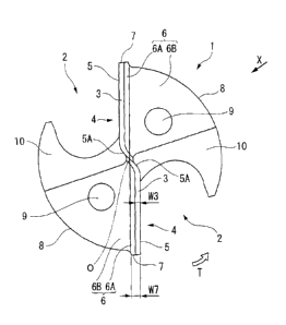
maximum value and the minimum value was larger than 2/5 times the width W7
(larger
than 0.2 mm), among drills produced so that the thickness W3 of the PCD layer
3 was
1/2 times the width W7 (0.5 mm) of the margin portion 7. As a result, the
number of
drilled holes was 82. Even in the drill produced so that the thickness W3 of
the same
PCD layer 3 was 1/2 times the width W7 of the margin portion 7, the cutting
edge 5 was
likely to fracture due to influence of stress concentrated in the PCD layer 3,
the tool life
thereof was shortened, and thereby the number of drilled holes was small, in
comparison
with Examples 1-4 to 1-6 where a difference between the maximum value and the
minimum value of the thickness W3 was in the range equal to or smaller than
2/5 times
the width W7. Similarly, in Examples 1-10 to 1-12 where the thickness W3 of
the PCD
layer 3 was 1/2 times the width W7 of the margin portion 7 and a difference
between the
maximum value and the minimum value of the thickness W3 was larger than 2/5
times
the width W7, the number of drilled holes was smaller than that in Examples 1-
4 to 1-6
where the thickness W3 of the PCD layer 3 was 1/2 times the width W7 of the
margin
portion 7 and a difference between the maximum value and the minimum value of
the
thickness W3 was in the range equal to or smaller than 2/5 times the width W7.
On the
CA 02943922 2016-09-26
other hand, since the thickness W3 of the PCD layer 3 was 1/2 times the width
W7 of the
margin portion 7, the number of drilled holes was larger than that in
Comparative
examples 1-1 to 1-9.
[Example 2]
5 [0050]
Next, in Example 2, double-edge twist drills, each of which includes cutting
edges 5 including outer peripheral portions having the shape of a concave
curve and
formed at ridge portions of rake faces 4 at a tip side of the tool body 1,
were produced on
the basis of the above-mentioned second embodiment. As in Example 1, three
10 double-edge twist drills were produced to satisfy conditions where the
thickness W3 (i.e.,
the thickness of the PCD layer 3 exposed to the first flank 6A) was 1/3, 1/2
or 1 times the
width W7 (i.e., the width of the margin portion 7) and a difference between
the maximum
value and the minimum value of the thickness W3 was equal to or smaller than
2/5 times
the width W7. These drills were referred to as Examples 2-1 to 2-9 as shown in
Table 2.
15 Further, three drills as Examples 2-10 to 2-12 were also produced where
the thickness
W3 of the PCD layer 3 was 1/2 times the width W7 of the margin portion 7 and a
difference between the maximum value and the minimum value of the thickness W3
of
the PCD layer 3 was larger than 2/5 times the width W7. Similarly, as
Comparative
examples, drills having the same shape of the cutting edge 5 as Examples 2-1
to 2-12
20 were also produced. Three drills as Comparative examples 2-1 to 2-3 were
produced
where a difference between the maximum value and the minimum value of the
thickness
W3 of the PCD layer 3 was equal to or smaller than 2/5 times the width W7 and
the
thickness W3 of the PCD layer 3 was 1/4 times the width W7 of the margin
portion 7,
three drills as Comparative examples 2-4 to 2-6 were produced where a
difference
25 between the maximum value and the minimum value of the thickness W3 of
the PCD
CA 02943922 2016-09-26
26
layer 3 was equal to or smaller than 2/5 times the width W7 and the thickness
W3 of the
PCD layer 3 was 3/2 times the width W7 of the margin portion 7, and three
drills as
Comparative examples 2-7 to 2-9 were produced where a difference between the
maximum value and the minimum value of the thickness W3 of the PCD layer 3
exceeded 2/5 times the width W7 and the thickness W3 of the PCD layer 3 was
3/2 times
the width W7 of the margin portion 7. The thickness W3 of the PCD layer 3 of
each of
Examples 2-1 to 2-12 and Comparative examples 2-1 to 2-9 was measured by the
same
method as in Example 1. The results thereof are shown in Table 2.
[0051]
Then, in Example 2, drilling was performed using these drills to form
through-holes in a work material made of only CFRP and having a thickness of
10 mm.
The number of drilled holes was measured at the time of fracture occurring on
the cutting
edge 5 or the wear width of the cutting edge 5 reaching 0.2 mm. The diameter
of each
of the drills of Examples 2-1 to 2-12 and Comparative examples 2-1 to 2-9 was
10 mm
and the width W7 of the margin portion 7 thereof was 0.9 mm. Further, the
average
diamond grain size of the PCD layer 3 was 3 Itm and was smaller than that of
Example 1,
and the Co content of the PCD layer 3 was 16 vol%. Furthermore, the drilling
was
performed without a step feed by dry working in which a cutting speed was 350
m/min
and a feed speed was 0.1 mmirev. The results thereof are shown in the
following Table
2.
27
[0052]
[Table 2]
Thickness of PCD layer relative
1/4 times 1/3 times 1/2 times 1 time 3/2
times 1/2 times 3/2 times
to width of margin portion
_
Difference between maximum
value and minimum value of
thickness of PCD layer relative to 0.13 0.09 0.13
0.12 0.13 0.95 2.85
width of margin portion
[mm]
9
Comparative Example 2-1 Example 2-4 Example 2-7 Comparative Example 2-10
Comparative 2
example 2-1
example 2-4 example 2-7 g
336 525 611 486 292
342 42 2
Comparative Example 2-2 Example 2-5 Example 2-8 Comparative Example 2-11
Comparative
The number of drilled holes
example 2-2 example 2-5 example 2-8
402 521 670 475 369
304 23 .
_______________________________________________________________________________
_____________ , ______
Comparative Example 2-3 Example 2-6 Example 2-9 Comparative Example 2-12
Comparative
example 2-3
example 2-6 example 2-9
279 498 623 472 340
421 84
CA 02943922 2016-09-26
28
[0053]
According to the results of Table 2, among Comparative examples 2-1 to 2-9, in
Comparative examples 2-7 to 2-9 where a difference between the maximum value
and
the minimum value of the thickness W3 of the PCD layer 3 exceeded 2/5 times
the width
W7 (exceeded 0.36 mm), the number of drilled holes did not reach 100 at most
and the
drills reached the end of their tool life early due to cracks of the PCD layer
3 caused by
stress concentration. Further, in Comparative examples 2-1 to 2-3 where a
difference
between the maximum value and the minimum value of the thickness W3 of the PCD
layer 3 was equal to or smaller than 2/5 times the width W7 (equal to or
smaller than 0.36
mm) and the thickness W3 of the PCD layer 3 was 1/4 times the width W7 of the
margin
portion 7 and Comparative examples 2-4 to 2-6 where a difference between the
maximum value and the minimum value of the thickness W3 of the PCD layer 3 was
equal to or smaller than 2/5 times the width W7 and the thickness W3 of the
PCD layer 3
was 3/2 times the width W7 of the margin portion 7, the number of drilled
holes was 402
at most, and the drills reached the end of their tool life due to the fracture
of the cutting
edge 5.
[0054]
In contrast, in the drills of Examples 2-1 to 2-9 where the thickness W3 of
the
PCD layer 3 was in the range of 1/3 to 1 times the width W7 of the margin
portion 7 and
a difference between the maximum value and the minimum value was equal to or
smaller
than 2/5 times the width W7 (equal to or smaller than 0.36 mm), at least 472
holes could
be formed and holes close to 500 could be drilled. Further, as in Examples 1-1
to 1-6,
in Examples 2-1 to 2-6 where a difference between the maximum value and the
minimum value of the thickness W3 of the PCD layer 3 was equal to or smaller
than 2/5
times the width W7 (equal to or smaller than 0.36 mm) and the thickness W3 of
the PCD
CA 02943922 2016-09-26
29
layer 3 was in the range of 1/3 to 1/2 times the width W7 of the margin
portion 7, the
number of drilled holes was larger than that in Examples 2-7 to 2-9 where a
difference
between the maximum value and the minimum value of the thickness W3 of the PCD
layer 3 was equal to or smaller than 2/5 times the width W7 and the thickness
W3 of the
PCD layer 3 was equal to the width W7 of the margin portion 7. Particularly,
in all of
Examples 2-4 to 2-6 where a difference between the maximum value and the
minimum
value of the thickness W3 of the PCD layer 3 was equal to or smaller than 2/5
times the
width W7 and the thickness W3 of the PCD layer 3 was 1/2 times the width W7 of
the
margin portion 7, the number of drilled holes exceeded 600 and the tool life
of each tool
was further increased. Furthermore, in Examples 2-10 to 2-12 where the
thickness W3
of the PCD layer 3 was 1/2 times the width W7 of the margin portion 7 and a
difference
between the maximum value and the minimum value of the thickness W3 was larger
than
2/5 times the width W7 (larger than 0.36 mm), the number of drilled holes was
smaller
than that in Examples 2-4 to 2-6 where the thickness W3 of the PCD layer 3 was
1/2
times the width W7 of the margin portion 7 and a difference between the
maximum value
and the minimum value of the thickness W3 was equal to or smaller than 2/5
times the
width W7. However, since the thickness W3 of the PCD layer 3 was 1/2 times the
width W7 of the margin portion 7, the average number of drilled holes was
larger than
that in Comparative examples 2-1 to 2-9.
[Example 3]
[0055]
In addition, in Example 3, three end mills, in each of which the present
invention
was applied to the above-mentioned end mill, were produced to satisfy
conditions where
the thickness W13 (i.e., the thickness of the PCD layer 13 exposed to the
margin portion
(the first outer peripheral flank face) in the circumferential direction) was
1/3, 1/2 or 1
CA 02943922 2016-09-26
times the width W17 (i.e., the width of the margin portion 17 in the
circumferential
direction) and a difference between the maximum value and the minimum value of
the
thickness W13 was equal to or smaller than 2/5 times the width W17. These end
mills
were referred to as Examples 3-1 to 3-9 as shown in Table 3. Further, three
end mills as
5 Examples 3-10 to 3-12 were also produced where the thickness W13 of the
PCD layer 13
was 1/2 times the width W17 of the margin portion 17 and a difference between
the
maximum value and the minimum value of the thickness W13 of the PCD layer 13
was
larger than 2/5 times the width W17. As Comparative examples to compare with
these
examples, three end mills as Comparative examples 3-1 to 3-3 were produced
where a
10 difference between the maximum value and the minimum value of the
thickness W13
was equal to or smaller than 2/5 of the width W17 and the thickness W13 was
1/4 times
the width W17, three end mills as Comparative examples 3-4 to 3-6 were
produced
where a difference between the maximum value and the minimum value of the
thickness
W13 was equal to or smaller than 2/5 of the width W17 and the thickness W13
was 3/2
15 times the width W17, and three end mills as Comparative examples 3-7 to
3-9 were
produced where a difference between the maximum value and the minimum value of
the
thickness W13 exceeded 2/5 of the width W17 and the thickness W13 was 3/2
times the
width W17, in which the thickness W13 was the thickness of the PCD layer 13
exposed
to the margin portion (the first outer peripheral flank face) in the
circumferential
20 direction and the width W17 was the width of the margin portion 17 in
the
circumferential direction. The thicknesses of the PCD layer 13 in the
direction
orthogonal to the ridge of the cutting edge were measured by observing the PCD
layer 13
from the tip side in the axis direction by a stereoscopic microscope, at each
of six points,
which equally divided a line of the PCD layer 13 along the ridge of the
cutting edge from
25 the inner peripheral end close to the axis 0 to the outer peripheral end
into five pieces, in
CA 02943922 2016-09-26
31
Examples 3-1 to 3-12 and Comparative examples 3-1 to 3-9. Then, the average
value of
the thicknesses of the PCD layer 13 at 24 points, which were measured in PCD
layers 13
formed in four different cutting edges 15, was regarded as the thickness W13
of the PCD
layer 13. Further, points in which thicknesses of the PCD layer 13 were the
thinnest and
the thickest were identified, respectively, by observing the entire PCD layer
13 by a
stereoscopic microscope: and they were regarded as the minimum value and the
maximum value of the thicknesses of the PCD layer, respectively. The results
thereof
are shown in Table 3.
[0056]
Then, trimming was performed using these end mills to cut an unwanted portion
of an opening edge of a window frame-shaped work material made of only CFRP
and
having a thickness of 20 mm. A cutting length was measured at the time of
fracture
occurring on the cutting edge (peripheral cutting edge) or the wear width of
the cutting
edge (peripheral cutting edge) reaching 0.2 mm. Each of these end mills was a
four-edge square end mill of which the diameter was 10 mm and the width of the
margin
portion 7 was 0.7 mm. The average diamond grain size of the PCD layer was 3 um
and
was small as in Example 2, and the Co content of the PCD layer was 16 vol%.
Further,
a working condition was dry working in which a cutting speed was 200 m/rnin, a
feed
speed was 700 min/min, and the depth of a cut was 5 mm. The results thereof
are
shown in the following Table 3.
32
[0057]
[Table 31
Thickness of PCD layer relative
1/4 times 1/3 times 1/2 times 1 time 3/2
times 1/2 times 3/2 times
to width of margin portion
=
Difference between maximum
value and minimum value of
thickness of PCD layer relative to 0.13 0.09 0.13
0.12 0.13 0.75 2.85
width of margin portion
[mm]
Comparative Example 3-1 Example 3-4 Example 3-7 Comparative Example 3-10
Comparative 9
2
example 3-1
example 3-4 example 3-7 g
12 m 20m 25m 18m 13m
16m 6m 2
Comparative Example 3-2 Example 3-5 Example 3-8 Comparative Example 3-11
Comparative 2
Cutting length example 3-2
example 3-5 example 3-8 Z
13m 21m 24m 19m 12m
24m 10 m
Comparative Example 3-3 Example 3-6 Example 3-9 Comparative Example 3-12
Comparative
example 3-3
example 3-6 example 3-9
12m 19m 24m 18m 13m
13m 11 m
CA 02943922 2016-09-26
33
[0058]
According to the results of Table 3, among Comparative examples 3-1 to 3-9, in
Comparative examples 3-7 to 3-9 where a difference between the maximum value
and
the minimum value of the thickness W13 of the PCD layer 13 exceeded 2/5 of the
width
W17 of the margin portion 17 (exceeded 0.28 mm), cracks caused by stress
concentration
were generated in the PCD layer 13, so that the end mills reached the end of
their tool life
at a cutting length of 11 in at most. Further, even in Comparative examples 3-
1 to 3-3
where a difference between the maximum value and the minimum value of the
thickness
WI3 of the PCD layer 13 was equal to or smaller than 2/5 times the width W17
(equal to
or smaller than 0.28 mm) and the thickness W13 of the PCD layer 13 was 1/4
times the
width W17 of the margin portion 17 and Comparative examples 3-4 to 3-6 where a
difference between the maximum value and the minimum value of the thickness
W13 of
the PCD layer 13 was equal to or smaller than 2/5 times the width W17 (equal
to or
smaller than 0.28 mm) and the thickness W13 of the PCD layer 13 was 3/2 times
the
width W17 of the margin portion 17, the end mills reached the end of their
tool life due
to the fracture of the peripheral cutting edge formed on the PCD layer when a
cutting
length was about 13 m.
[0059J
In contrast, among the end mills of Examples 3-1 to 3-9 where a difference
between the maximum value and the minimum value of the thickness W13 of the
PCD
layer 13 was equal to or smaller than 2/5 times the width W17 (equal to or
smaller than
0.28 mm) and the thickness W13 of the PCD layer 13 was in the range of 1/3 to
1 times
the width W17 of the margin portion 17, a cutting length was 18 m even in
Examples 3-7
and 3-9 having the shortest cutting length. Among Examples 3-1 to 3-3 where
the
thickness W13 of the PCD layer 13 was 1/3 times the width W17 of the margin
portion
CA 02943922 2016-09-26
34
17, a cutting length was 19 m even in Example 3-3 having the shortest cutting
length.
Particularly, a cutting length exceeding 20 m could be obtained in all of
Examples 3-4 to
3-6 where the thickness W13 of the PCD layer 13 was 1/2 times the width W17 of
the
margin portion 17. Further, in Examples 3-10 to 3-12 where the thickness W13
of the
PCD layer 13 was 1/2 times the width W17 of the margin portion 17 and a
difference
between the maximum value and the minimum value of the thickness W13 was
larger
than 2/5 times the width W17 (larger than 0.28 mm), a cutting length was
shorter than
that in Examples 3-4 to 3-6 where the thickness W13 of the PCD layer 13 was
1/2 times
the width W17 of the margin portion 17 and a difference between the maximum
value
and the minimum value of the thickness W13 was equal to or smaller than 2/5
times the
width W17. However, since the thickness W13 of the PCD layer 13 was 1/2 times
the
width W17 of the margin portion 17, the average cutting length was longer than
that in
comparative examples 3-1 to 3-9.
[0060]
According to the results of Examples 1 to 3, it was found that fracturing
resistance was excellent in the tools in which the thickness of the PCD layer
was 1/3 to 1
times, particularly, 1/3 to 1/2 times the width of the margin portion. In
addition, it was
found that fracturing resistance was further excellent when a difference
between the
maximum value and the minimum value of the thickness of the PCD layer was
equal to
or smaller than 2/5 times the width of the margin portion.
Furthermore, according to the results of Examples 1, 2, and 3, it was
desirable
that the diamond grain size of the PCD layer be large in a case where a work
material
was a composite material of difficult-to-cut materials, such as CFRP-Ti or
CFRP-Al, and
the diamond grain size of the PCD layer be small in a case where a work
material was
.. fiber-reinforced plastic, such as CFRP or GFRP.
CA 02943922 2016-09-26
INDUSTRIAL APPLICABILITY
[0061]
In the rotary cutting tool including a polycrystalline diamond material of the
5 present invention, sufficient fracturing resistance of the PCD layer on
which the cutting
edge is formed can be ensured while suppressing wear from reaching the carbide
substrate made of cemented carbide early. Accordingly, the rotary cutting tool
including a polycrystalline diamond material of the present invention is
suitable to cut
CFRP or a composite material thereof.
REFERENCE SIGNS LIST
[0062]
1: TOOL BODY
2: FLUTE
3: PCD LAYER (POLYCRYSTALLINE DIAMOND LAYER)
4: RAKE FACE
5: CUTTING EDGE
5A: THINNING EDGE
6: FLANK
6A: FIRST FLANK
6B: SECOND FLANK
7: MARGIN PORTION
0: AXIS OF TOOL BODY 1
T: ROTATION DIRECTION
W3: THICKNESS OF PCD LAYER 3
CA 02943922 2016-09-26
. ,
36
W7: WIDTH OF MARGIN PORTION 7