Note: Descriptions are shown in the official language in which they were submitted.
CA 02944064 2017-01-24
- 1 -
Elevator having a brake apparatus
Field
Disclosed herein is an elevator having a brake apparatus, in particular a
safety
apparatus or a service brake.
Prior art
In the case of elevators, there is an imperative need for safety apparatuses
and
service brakes which, in the event of overspeeding or uncontrolled traveling
movements, decelerate the elevator car of the elevator safely to a standstill,
and
which hold the elevator car while it is at a standstill.
Safety apparatuses and service brakes generally do not offer the possibility
of
adjustment of the braking force. That is to say, they generate a constant
braking
force. Depending on the load state of the elevator car, the passengers are
then
subjected to different levels of deceleration during a braking process. In
particular
in the case of a low load, it is then the case, for example, that the
passengers are
subjected to very high levels of deceleration, whereby, for example, the
traveling
comfort may be reduced or the risk of an accident may be increased.
EP 0650703 Al has disclosed an elevator having a brake, the brake force of
which
can be regulated. However, said brake has a complex construction, which is for
example considered to be relatively maintenance-intensive.
- 2 -
There is therefore a demand for an elevator having a brake apparatus which
provides a suitable braking force in accordance with the respective situation
but
which is characterized by a simple construction.
Disclosure
Disclosed herein is an elevator having a brake apparatus, and a brake
apparatus of
this type. The following description relates to advantageous refinements.
The elevator according to selected embodiments has a brake apparatus, in
particular a safety apparatus or a service brake, wherein the brake apparatus
is
designed to generate a stepped braking force for braking an elevator car of
the
elevator.
Certain exemplary embodiments provide an elevator having a brake apparatus,
which brake apparatus is a safety apparatus or a service brake, wherein the
brake
apparatus is designed to generate a stepped braking force for braking an
elevator
car of the elevator, wherein the brake apparatus has a multiplicity of
individually
actuable brake cylinder assemblies comprising springs, and wherein the brake
cylinder assemblies are designed to generate different braking forces, wherein
the
springs of the brake cylinder assemblies are of different strengths to
generate the
different braking forces.
Certain exemplary embodiments further provide a brake apparatus, which is a
safety apparatus or a service brake of an elevator as defined herein, wherein
the
brake apparatus is designed for generating a stepped braking force for braking
an
elevator car of the elevator, wherein the brake apparatus has a multiplicity
of
individually actuable brake cylinder assemblies comprising springs, wherein
the
springs of the brake cylinder assemblies are of different strengths to
generate the
different braking forces.
CA 2944064 2018-05-04
- 2a -
Embodiments are based on the realization that it is sufficient for the braking
force
to be provided in a stepped fashion in a number of discrete braking steps.
Accordingly, for example in the event of an emergency stop, the passengers in
the
cabin are not subjected to excessive deceleration, regardless of the state of
load of
CA 2944064 2018-05-04
CA 02944064 2017-01-24
- 3 -
the elevator car. A brake apparatus of this type has a considerably simpler
construction than a brake that is adjustable in continuously variable fashion.
In one advantageous refinement of certain embodiments, the brake apparatus has
a multiplicity of individually actuable brake cylinder assemblies. It is
advantageously the case that two to five brake cylinder assemblies are
provided. If
all of the brake cylinder assemblies are actuated at the same time, a maximum
braking force value is provided. By contrast, if only some of the brake
cylinder
assemblies are actuated, a corresponding partial braking force value is
provided. It
is thus possible to provide a brake apparatus which has a particularly simple
construction.
In an advantageous refinement of certain embodiments, the brake cylinder
assemblies are designed to each generate a substantially identical braking
force
value. In this case, a substantially identical braking force value is to be
understood
to mean a braking force value which fluctuates for example within
manufacturing-
induced component tolerances, for example by 5%, 10% or 20%. Accordingly, the
brake apparatus can be formed from structurally identical brake cylinder
assemblies, which simplifies manufacture and maintenance.
In one advantageous refinement of certain embodiments, the brake cylinder
assemblies are designed to generate different braking force values. In this
way,
through the selection of individual brake cylinder assemblies, it is possible
to
realize precise metering of the braking force, in particular of two to five,
for
example three brake cylinder assemblies.
In one advantageous refinement of certain embodiments, the brake apparatus has
at least one first brake cylinder assembly and one second brake cylinder
assembly.
The first brake cylinder assembly is designed to generate a first braking
force value
and the second brake cylinder assembly is designed to generate a second
braking
force value. In this case, the second braking force value is greater than the
first
CA 02944064 2017-01-24
- 4 -
braking force value, in particular is substantially twice as great as the
first braking
force value. A braking force which is substantially twice as great is in this
case to
be understood to mean a braking force value which fluctuates for example
within
manufacturing-induced component tolerances, for example by 5%, 10% or 20%.
Thus, different braking force values can be provided by actuation of one brake
cylinder assembly and actuation of the other brake cylinder assembly, such
that a
braking force can be provided in multiple braking force steps.
In an advantageous refinement, the brake apparatus has at least one further
brake
cylinder assembly. The further brake cylinder assembly is designed to generate
a
further braking force value. In this case, the further braking force value is
three to
five times, in particular substantially four times, as great as the first
braking force
value. A braking force value which is substantially four times as great is in
this case
to be understood to mean a braking force value which fluctuates for example
.. within manufacturing-induced component tolerances, for example by 5%, 10%
or
20%. Thus, an even greater number of different braking force values can be
provided by actuation of a further brake cylinder assembly, such that the
number
of braking force steps can be further increased.
In one advantageous refinement, each brake cylinder assembly is assigned at
least
in each case one valve for the actuation of the brake cylinder assembly. If,
in the
event of a fault, a valve for the actuation of one brake cylinder assembly
becomes
non-functional, it is possible for at least other brake cylinder assemblies to
be
actuated by way of their respective valves, and thus a partial braking force
can be
provided. Operational safety is thus increased.
In one advantageous refinement, the brake apparatus has two brake units, of
which a first brake unit is assigned to a first guide rail of the elevator and
a second
brake unit is assigned to a second guide rail of the elevator, wherein each
brake
unit has in each case one brake cylinder assembly, wherein a brake cylinder
assembly of the first brake unit and a brake cylinder assembly of the second
brake
CA 02944064 2017-01-24
- 5 -
unit are assigned to in each case one valve assembly for the actuation of the
brake
units. Thus, owing to the actuation of the two braking units by way of one
valve
assembly, a symmetrical deceleration of the elevator car at both guide rails
is
attained.
In one advantageous refinement, the two brake units have the same number of
brake cylinder assemblies. It is thus possible for the two brake units to be
of
structurally identical form, which simplifies manufacture and maintenance.
Further advantages and refinements of the foregoing embodiments will emerge
from the description and from the appended drawing.
It is self-evident that the features mentioned above and the features yet to
be
discussed below may be used not only in the respectively specified combination
but also in other combinations or individually without departing from the
scope of
the present invention.
Selected embodiments are schematically illustrated on the basis of an
exemplary
embodiment in the drawing, and will be described in detail below with
reference
to the drawing.
Description of the figures
Figure 1 schematically shows a preferred embodiment of an elevator
according to the invention having a brake apparatus, in a schematic
illustration.
Figure 2 schematically shows a section through a preferred embodiment of
a
brake apparatus as per Figure 1 which can be used in accordance
with the invention.
CA 02944064 2017-01-24
- sa -
Figure 3 schematically shows a circuit configuration of brake cylinder
assemblies with valves, as per a first exemplary embodiment.
Figure 4 schematically shows a circuit configuration of brake cylinder
assemblies with valves, as per a second exemplary embodiment.
Figure 5 schematically shows a further alternative circuit
configuration.
Figure 1 schematically illustrates an elevator 2 as a preferred refinement of
an
elevator system according to certain embodiments of the invention.
CA 02944064 2016-09-27
- 6 -
In the present exemplary embodiment, the elevator 2 has an elevator car 4 for
the
transportation of passengers and/or loads, which elevator car is mounted on
two
guide rails 6a, 6b, which run parallel to one another, in an elevator shaft
such that
said elevator car can travel in or counter to the direction of gravitational
force g. By
contrast to the present exemplary embodiment, it is however for example also
possible for the elevator car 4 to be mounted, such that it can travel, on a
single
guide rail.
For the travel of the elevator car 4, a drive is provided which, in the
present
exemplary embodiment, is in the form of a driving-pulley drive. In this case,
the
elevator car 4 may have a cabin and a safety frame (neither of which are
illustrated). In the present exemplary embodiment, the drive has a supporting
cable 8 which is fastened to the top side of the elevator car 4. The
supporting cable
8 runs on a driving pulley 12 which can be motor-driven by means of a motor
(not
illustrated) in order to cause the elevator car 4 to travel. In the present
exemplary
embodiment, a counterweight 10 is fastened to the other end, which is situated
opposite the elevator car 4, which counterweight 10, by weight balancing,
reduces
the force expenditure required for causing the elevator car 4 to travel. By
contrast
to the present exemplary embodiment, the elevator may be designed as an
elevator
without supporting means. An elevator without supporting means is an elevator
system which does not use cables or belts which are driven by means of a
driving
pulley 12. The drive of such elevators is situated directly on the elevator
car 4.
Here, use is made, for example, of toothed-rack drives and linear drives.
To brake the elevator car 4 to a standstill, for example if overspeeding
and/or
uncontrolled traveling movements of the elevator car 4 occur, a brake
apparatus
14 is provided, which in the present exemplary embodiment is in the form of a
safety apparatus and/or service brake.
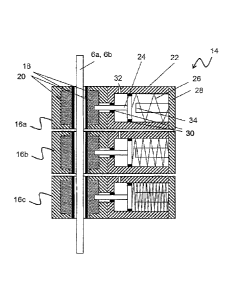
Figure 2 shows the brake apparatus 14 in detail.
CA 02944064 2016-09-27
=
- 7 -
In the present exemplary embodiment, the brake apparatus 14 comprises in each
case three brake cylinder assemblies 16a, 16b, 16c, which are arranged to both
sides of the elevator car 4. By contrast to the present exemplary embodiment,
it is
however also possible for the brake apparatus 14 to have only two, or more
than
three, for example four or five, brake cylinder assemblies. The brake cylinder
assemblies 16a, 16b, 16c interact with the guide rail 6a or 6b in order to
brake the
elevator car 4. For this purpose, each brake cylinder assembly 16a, 16b, 16c
has, to
both sides, in each case one brake pad 18 which, in the present exemplary
embodiment, is of flat, that is to say substantially cuboidal form. The brake
pads 18
are inserted into a respective brake pad holder 20 of each of the brake
cylinder
assemblies 16a, 16b, 16c. The brake cylinder assemblies 16a, 16b, 16c are
mounted in floating fashion, that is to say the brake cylinder assemblies 16a,
16b,
16c are mounted so as to be horizontally displaceable in order to ensure
uniform
abutment of the brake pads 18.
Each brake cylinder assembly 16a, 16b, 16c has a cylinder 22 in which a piston
24
is mounted in displaceable fashion, wherein the piston 24 is operatively
connected
to the brake pads 18 in order to place the latter in contact with the guide
rails 6a,
6b when the elevator car 4 is to be braked. The piston 24 is furthermore
subjected
to spring preload by means of a spring 26, which in the present exemplary
embodiment is in the form of a compression spring, wherein the spring 26
generates the contact pressure for placing the brake pads in contact with the
guide
rails 6a, 6b. In this case, a cover 28 closes off the cylinder 22, which is
open on one
side. Seals 30 are provided for sealing off the piston 24. Finally, each brake
cylinder
assembly 16a, 16b, 16c has a respective pressure medium port 32 for the
ventilation of the brake apparatus 14.
In the present exemplary embodiment, the brake cylinder assemblies 16a, 16b,
16c
are designed to generate different braking forces. In the present exemplary
embodiment, the first brake cylinder assembly 16a is designed to generate a
braking force value of 5 kN, the second brake cylinder assembly 16b is
designed to
CA 02944064 2016-09-27
- 8 -
generate a braking force value of 10 kN, and the third brake cylinder assembly
16c
is designed to generate a braking force value of 20 kN. By contrast to the
present
exemplary embodiment, the braking force values may also be staggered
differently.
Thus, the third brake cylinder assembly 16c generates a braking force value
which
is twice as great as the braking force value generated by the second brake
cylinder
assembly 16b. Furthermore, the second brake cylinder assembly 16b generates a
braking force value which is four times as great as the braking force value
generated by the first brake cylinder assembly 16a.
Thus, through individual actuation of selected brake cylinder assemblies 16a,
16b,
16c, it is possible for braking forces with values of 5 kN, 10 kN, 15 kN, 20
kN, 25
kN, 30 kN and 35 kN to be generated. The brake apparatus thus has seven
braking
force steps, and generates a stepped braking force with seven steps.
To generate the different braking forces, it is provided in the present
exemplary
embodiment that the springs 26 of the brake cylinder assemblies 16a, 16b, 16c
are
of different strength. If all of the brake cylinder assemblies 16a, 16b, 16c
are
charged with the same operating pressure, for example of the hydraulic oil,
different spring forces act in each of the brake cylinder assemblies 16a, 16b,
16c,
which spring forces lead to different deflections of the pistons 24 in each
case.
In the present exemplary embodiment, a stop 34 is provided in each cylinder
22,
which stop delimits a displacement travel of the piston 24. Instead of the
stop 34, it
would be possible for the base surface area of the pistons 24 of the brake
cylinder
assemblies 16a, 16b, 16c to be varied, or the brake cylinder assemblies 16a,
16b,
16c are charged with in each case different operating pressures in order to
generate different braking forces.
CA 02944064 2016-09-27
- 9 -
By contrast to this, it is however possible for the brake cylinder assemblies
16a,
16b, 16c to be designed to generate identical braking forces.
Figure 3 shows an exemplary embodiment of the brake apparatus 14 in which in
each case three brake cylinder assemblies 16a, 16b, 16c, 16a', 16b', 16c' are
provided for both sides of the elevator car 4.
In each case one valve 56 is assigned to a respective one of the brake
cylinder
assemblies 16a, 16b, 16c; 16a', 16b', 16c'.
For the supply of pressure to the brake apparatus 14, a motor-driven
compressor
36 is provided in the present exemplary embodiment. Between the compressor 36
and the valves 56 there is provided a pressure accumulator 38 which provides a
pressure higher than the minimum operating pressure of the brake apparatus 14.
At the same time, the pressure accumulator 38 serves as a buffer, for example
in
the event of an electrical failure. The pressure accumulator 38 then provides
a
reserve with which the elevator car 4 can be released from the arresting
action by
a triggered brake apparatus 14, for example in order that said elevator car
can be
caused to travel to a nearest stopping point of the elevator 2 for the
purposes of
passenger evacuation. Furthermore, the pressure accumulator 38 serves as a
reserve in the event of, for example, frequent switching cycles, such that a
smaller
compressor 36 can be used than in the case of a design without a pressure
accumulator 38.
Furthermore, in the present exemplary embodiment, a pressure limiting valve or
pressure regulating valve 40 is provided between the valves 56 and the
pressure
accumulator 38, as a pressure prevailing in the pressure accumulator 38 may be
higher than that required for the restoring movements of the brake cylinder
assemblies 16a, 16b, 16c; 16a', 16W, 16c' counter to the spring 26. In the
present
exemplary embodiment, the valves 56 themselves are in the form of 3/2
directional valves.
CA 02944064 2016-09-27
-
By contrast to the illustration in Figure 3, it is possible for in each case
two valves
56 connected in parallel to be provided for each of the brake cylinder
assemblies
16a, 16b, 16c, 16a', 16b', 16c' in order to provide redundancy.
5
The exemplary embodiment shown in Figure 4 differs from the exemplary
embodiment shown in Figure 3 in that the brake apparatus 14 has two brake
units
42, 44. The first brake unit 42 is assigned to the first guide rail 6a of the
elevator 2
and the second brake unit 44 is assigned to the second guide rail 6b of the
elevator
10 2. In the present exemplary embodiment, each brake unit 42, 44 has in
each case
three brake cylinder assemblies 16a, 16b, 16c and 16a', 16b', 16c'
respectively. In
this case, the brake cylinder assembly 16a of the first brake unit 42 and the
brake
cylinder assembly 16a' of the second brake unit 44 are assigned to a valve
assembly 46a with one of the valves 56. Furthermore, the brake cylinder
assembly
16b of the first brake unit 42 and the brake cylinder assembly 16b' of the
second
brake unit 44 are assigned to a second valve assembly 46b with one of the
valves
56. Finally, the brake cylinder assembly 16c of the first brake unit 42 and
the brake
cylinder assembly 16c' of the second brake unit 44 are assigned to a third
valve
assembly 46c with one of the valves 56. Thus, in the present exemplary
embodiment, the two brake units 42, 44 have the same number of brake cylinder
assemblies 16a, 16b, 16c and 16a', 16b', 16c' respectively. Furthermore, in
each
case two brake cylinder assemblies 16a, 16b, 16c and 16a', 16b, 16c'
respectively
arc assigned in each case one valve 56. Thus, through the actuation of the
respective valves 56, a braking force of equal magnitude is effected at both
guide
rails 6a and 6b, which yields a symmetrical deceleration of the elevator car 4
on
both sides in a simple manner.
By contrast to the illustration in the figure, it may be provided that each
valve
assembly 46a, 46b, 46c has in each case two valves 56 connected in parallel in
order to provide redundancy.
CA 02944064 2016-09-27
- 11 -
Figures 5a and 5b show, by way of example on the basis of the brake cylinder
assembly 16a, a further exemplary embodiment in which the valves 56 are in the
form of 4/2 directional valves. Furthermore, in this exemplary embodiment, the
brake cylinder assembly 16a is of double-acting design. Thus, when the brake
apparatus 14 is open, a first chamber 48 of the brake cylinder assembly 16a is
charged with a pressure medium, such as for example hydraulic oil, whereas
when
the brake apparatus 14 is closed, a second chamber 50 of the brake cylinder
assembly 16a is charged with the pressure medium. Thus, in addition to the
spring
force of the spring 26, the pressure medium acts on the piston 24 in order to
displace the latter. Furthermore, in the exemplary embodiment as per Figure 5,
a
check valve 52 and a collecting vessel 54 are provided.
During operation, a controller (not illustrated) measures the present
acceleration
and speed of the elevator car 4 and evaluates these with regard to whether
limit
values are overshot. The controller switches the brake cylinder assemblies
16a,
16b, 16c and 16a', 16b', 16c' in a manner dependent on the load state of the
elevator car 4. Furthermore, for reliable control, an emergency power
generator or
battery is provided in order that, in the event of an electrical failure, a
situation is
prevented in which all of the brake cylinder assemblies 16a, 16b, 16c and
16a',
16b', 16c abruptly engage and effect an excessive deceleration of the elevator
car
4.
The valves 56 are furthermore switched such that the safe state of the valves
56 in
the event of an electrical failure causes the brake apparatus 14 to be engaged
(activated).
CA 02944064 2016-09-27
- 12 -
List of reference signs
2 Elevator
4 Elevator car
6a Guide rail
6b Guide rail
8 Supporting cable
Counterweight
12 Drive pulley
10 14 Brake apparatus
16a Brake cylinder assembly
16a Brake cylinder assembly
16b Brake cylinder assembly
16b' Brake cylinder assembly
16c Brake cylinder assembly
16c' Brake cylinder assembly
18 Brake pad
Brake pad holder
22 Cylinder
20 24 Piston
26 Spring
28 Cover
Seal
32 Pressure medium port
25 34 Stop
36 Compressor
38 Pressure accumulator
Pressure limiting or pressure regulating valve
42 Brake unit
30 44 Brake unit
46a Valve assembly
CA 02944064 2016-09-27
- 13 -46b Valve assembly
46c Valve assembly
48 First chamber
50 Second chamber
52 Check valve
54 Collecting tank
56 Valve
Direction of gravitational force