Note: Descriptions are shown in the official language in which they were submitted.
SYSTEM AND METHOD FOR MOLDING MULTI-LAYER PLASTIC
ITEM USING MULTIPLE MOLD CORES
[0001] <Blank>
BACKGROUND OF THE INVENTION
[0002] The present invention relates generally to the field of plastic
molding. The present
invention relates specifically to a system and method of molding a plastic
item using more than
one mold core during molding.
[0003] Many commercial plastic containers are formed by blow-molding a
plastic preform
within a mold to form a plastic container of the desired size and shape.
Typically, the preform is
heated to a temperature that allows the material of the plastic to soften, and
air is blown into the
center of the preform causing the preform to expand into confluence with the
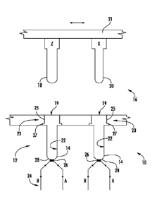
cavity of the blow
mold. In many conventional systems, the preform used during blow molding is
formed by
injection molding a single layer of plastic for create the preform. In other
conventional systems,
a multilayer preform is injection molded using an overmolding process. In the
overmolding
processes, the preform is formed by injection molding a first layer of plastic
around a single
mold core. Next, while leaving the single mold core in place, a second layer
of plastic is
injection molded around the outside of the first layer of plastic. Such
systems are typically
referred to as over-molding systems because each subsequent injection molded
layer is deposited
along the outer surface of a preceding layer in the molding process.
SUMMARY OF THE INVENTION
[0004] One embodiment of the invention relates to a method of injection
molding a plastic
preform. The method includes providing an injection mold system including an
inner surface
-1-
Date Recue/Date Received 2021-08-09
CA 02944173 2016-09-27
WO 2015/157079
PCT/US2015/024023
defining an injection mold cavity. The method includes positioning a first
core having an outer
surface within the injection mold cavity such that a first space is defined
between the inner
surface of the injection mold cavity and the outer surface of the first core.
The method includes
injecting a flowable first plastic material into the first space to form a
first preform layer having
an outer surface facing the inner surface of the injection mold cavity and an
inner surface facing
the first core. The method includes solidifying the first preform layer. The
method includes
removing the first core from the injection mold cavity such that the inner
surface of the first
perform layer defines a first preform cavity. The method includes positioning
a second core
having an outer surface within the injection mold cavity and within the first
preform cavity such
that a second space is defined between the inner surface of the first preform
layer and the outer
surface of the second core. The method includes injecting a flowable second
plastic material into
the second space to form a second preform layer having an outer surface
contacting the inner
surface of the first preform layer and an inner surface facing the second
core.
[0005] Another
embodiment of the invention relates to an injection molding system. The
injection molding system includes a mold body having an open end, a closed end
and an inner
surface defining a mold cavity shaped to form a plastic item. The injection
molding system
includes a gate extending through the closed end of the mold body. The
injection molding
system includes a resin injection system coupled to the gate. The gate is
moveable between a
closed position and an open position in which resin is delivered from the
resin injection system
through the gate into the mold cavity. The injection molding system includes a
first mold core
including an outer surface. The injection molding system includes a second
mold core including
an outer surface. An outer dimension of the outer surface of the first mold
core is greater than an
outer dimension of the outer surface of the second mold core. The injection
molding system
includes an actuator configured to move the first mold core into the mold
cavity, to remove the
first mold core from the mold cavity and to move the second mold core into the
mold cavity after
removal of the first mold core.
[0006] Another
embodiment of the invention relates to an injection molded preform. The
preform includes an outer layer formed from a first plastic material. The
outer layer has an inner
surface and an outer surface that defines an exterior sidewall surface of the
preform. The
-2-
preform includes a hole formed in the outer layer extending from the outer
surface of the outer
layer to the inner surface of the outer layer. The preform includes an inner
layer formed from a
second plastic material. The inner layer has an inner surface defining an
inner surface of the
preform and an outer surface. A portion of the inner layer extends through the
hole. The second
plastic material is a light transmitting material, and the first plastic
material is more opaque than
the second plastic material.
[0007] Alternative exemplary embodiments relate to other features and
combinations of
features.
BRIEF DESCRIPTION OF THE DRAWINGS
[0008] This application will become more fully understood from the
following detailed
description, taken in conjunction with the accompanying figures, wherein like
reference
numerals refer to like elements in which:
[0009] FIG. 1 is a diagram showing an injection molding system according to
an exemplary
embodiment.
[0010] FIG. 2 is a cross-sectional view showing formation of an outer layer
of a preform
using the system of FIG. 1 according to an exemplary embodiment.
[0011] FIG. 3 is a cross-sectional view showing formation of an inner layer
of a preform
using the system of FIG. 1 according to an exemplary embodiment.
[0012] FIG. 4 is a perspective view of a preform including at least one
window section
according to an exemplary embodiment.
[0013] FIG. 5 is a cross-sectional view of the preform of FIG. 4 according
an exemplary
embodiment.
DETAILED DESCRIPTION
[0014] Referring generally to the figures, various embodiments of a system
and method for
forming a multilayer blow-mold preform are shown and described. In other
embodiments, the
multi-core system described herein may be used for the molding of other
plastic items, e.g., vials,
thick-walled bottles, tubes, etc. In specific embodiments, the multi-layer
plastic components
-3-
Date Recue/Date Received 2021-08-09
CA 02944173 2016-09-27
WO 2015/157079 PCT/US2015/024023
and/or multi-layer plastic preforms discussed herein are molded using a system
and process that
molds the outermost layer of the preform first and forms each subsequent layer
inside of the
adjacent outer layer. In specific embodiments, the system and method discussed
herein utilize
multiple mold cores of differing diameters during preform molding.
[0015] To form the first, outermost component or preform layer, a first
mold core is
positioned in the cavity of the injection mold body, and the resin material of
the first preform
layer is injected into the space between the outer surface of the first mold
core and the mold
cavity. Once the resin material of the first layer cools and solidifies, the
first mold core is
removed from the injection mold cavity. Next, a second mold core that is
smaller than the first
mold core is positioned within the injection mold cavity and also within the
first preform layer.
In this position, the resin material of the second preform layer is injected
into the space between
the outer surface of the second mold core and the inner surface of the first
preform layer. Once
the material of the second preform layer solidifies, the second mold core is
removed and the
finished preform is removed from the injection mold.
[0016] Thus, the system and process discussed herein forms a multi-layer
preform by
forming each layer of the preform inside of an outer preform layer. In
contrast to conventional
overmolding processes, the process described herein allows each layer of the
preform to be
molded while in direct contact with a mold core. This arrangement is believed
to allow each
preform layer to be cooled more quickly due to contact with the mold core, in
comparison to
overmolding techniques where each subsequent layer has a layer of plastic
between the newly
injected layer and the mold core. Allowing for fast cooling may be
advantageous for a variety of
reasons including limiting crystallization that is common with PET resin that
is cooled slowly.
Further it is believed that the system and process discussed herein allows for
the formation of
preforms having a thicker sidewall with better and more precisely controlled
material properties
than other conventional preform injection molding systems, such as overmolding
systems.
[0017] Referring to FIG. 1, an injection mold system 10 configured to
produce a multilayer
plastic item, such as a blow-mold preform, is shown according to an exemplary
embodiment.
Generally, injection mold system 10 includes a mold body 12 that includes a
plurality of mold
cavities 14. System 10 includes a mold core assembly, generally shown as core
insert assembly
-4-
CA 02944173 2016-09-27
WO 2015/157079 PCT/US2015/024023
16. In general, core insert assembly 16 includes multiple larger mold cores 18
and multiple
smaller mold cores 20. In such embodiments, larger mold cores 18 have an outer
surface having
an outer dimension that is greater than an outer dimension of the outer
surface of smaller mold
cores 20. In the embodiment shown in FIG. 1, each mold core 18 and each mold
core 20 have an
outer surface that includes a cylindrical portion, and in such embodiments,
the diameter of the
cylindrical outer surface of mold core 18 is greater than the diameter of the
cylindrical outer
surface of mold core 20.
[0018] System 10 also includes an actuator, shown as mold core actuator 21.
Mold core
actuator 21 is an actuation device configured to or operable to move mold
cores 18 and 20 into
and out of mold cavities 14. Mold core actuator 21 is also configured to index
mold cores 18 and
20 relative to mold cavities 14 to alternately position mold core 20 into each
cavity 14 following
removal of mold core 18 into a given cavity to form the two layer perform
discussed below. In
the embodiment shown, each mold cavity 14 includes an open end 19, and mold
core actuator 21
is configured to move mold cores 18 and 20 into and out of mold cavities 14
through open end
19 via operation of mold core actuator 21.
[0019] Each mold cavity 14 includes an inner surface 22 that is shaped to
create the contours
of the outer surface of the preform, and, as will be explained in more detail
below, the outer
surface of smaller diameter mold cores 20 are shaped to create the contours of
the inner surface
of the preform formed using injection mold system 10. In some embodiments
configured for
formation of a blow-mold preform (i.e., a preform intended for use during blow
molding to form
a blow molded container), inner surface 22 includes an upper portion 23 with
contours shaped to
form threading 25 and a collar 27 on the outer surface of the molded preform.
Injection mold
system 10 utilizing mold cavity 14 and mold cores 18 and 20 allows for a
preform to be formed
with precisely controlled inner and outer diameters, and also allows for a
preform having
multiple layers and may also allows for formation of preforms that are thicker
and/or have
superior material properties than preforms formed using overmolding or other
conventional
molding systems.
[0020] Injection mold system 10 includes a resin injection system 24 that
is in fluid
communication with cavity 14 such that liquid resin is permitted to flow into
mold cavity 14 to
-5-
CA 02944173 2016-09-27
WO 2015/157079 PCT/US2015/024023
produce a preform. In one embodiment, resin injection system 24 includes a
gate 26 located
through the closed end 28 of each mold cavity 14. In general, gate 26 is a
mechanical structure
that selectively opens and closes to control flow of liquid resin from resin
injection system 24 to
mold cavity 14. In another embodiment, resin injection system 24 may be a
thermal gated
system in which the opening into the injection mold cavity remains open and
flow of liquid resin
into mold cavity 14 is controlled by controlling the temperature and/or
pressure of the liquid
resin within resin injection system 24.
[0021] Referring to FIG. 2 and FIG. 3, formation of a multilayer preform,
shown as preform
30, utilizing injection mold system 10 is shown according to an exemplary
embodiment.
Referring specifically to FIG. 2, the molding of a first preform layer, shown
as outer layer 32, is
shown according to an exemplary embodiment. To form outer layer 32, larger
diameter mold
core 18 is located within mold cavity 14 such that a space 34 is defined
between inner surface 22
of mold cavity 14 and the outer surface of mold core 18, and this space has a
width W1 that
corresponds to the thickness of outer layer 32 following injection molding.
[0022] To form outer layer 32, gate 26 opens allowing resin injection
system 24 to inject a
flowable first plastic material, shown as molten resin A, into the space 34.
With gate 26 is the
first open position shown in FIG. 2, a fluid path is defined through from
supply 36 of resin A,
through conduit 38, through gate 26 and into space 34. The fluid path allows
the flowable resin
A to be delivered from supply 36 into space 34. After a sufficient amount of
resin A has been
delivered to fill space 34, resin A within space 34 is allowed to solidify,
typically by cooling, to
form a solid outer layer 32.
[0023] Outer layer 32 includes a channel 40 extending through outer layer
32 that provides a
passageway for a second resin material to be delivered to the interior surface
of outer layer 32.
In one embodiment, a cylindrical wall is located or inserted into flowable
material of outer layer
32 prior to solidification that acts to block the area for channel 40, and
following solidification,
the cylindrical wall is removed leaving channel 40. In another embodiment,
channel 40 is
formed following solidification of the material of outer layer 32, for example
via mechanical or
laser drilling.
-6-
CA 02944173 2016-09-27
WO 2015/157079 PCT/US2015/024023
[0024] Referring specifically to FIG. 3, the molding of a second preform
layer, shown as
inner layer 42, is shown according to an exemplary embodiment. To form inner
layer 42,
smaller diameter mold core 20 is located within mold cavity 14 and within a
cavity defined by
the inner surface of outer layer 32 such that a space 44 is defined between
inner surface 46 of
outer layer 32 and the outer surface of mold core 20, and this space has a
width W2 that
corresponds to the thickness of inner layer 42 following injection molding.
[0025] To form inner layer 42, gate 29 opens allowing resin injection
system 24 to inject a
flowable second plastic material, shown as molten resin B, into the space 44.
With gate 29 is the
second open position shown in FIG. 3, a fluid path is defined from supply 48
of resin B, through
conduit 50, through gate 29, through channel 40 through outer layer 32 and
into space 44. The
fluid path allows the flowable resin B to be delivered from supply 48 into
space 44. After a
sufficient amount of resin B has been delivered to fill space 44, resin B
within space 44 is
allowed to solidify, typically by cooling, to form a solid inner layer 42. In
a two layer version of
preform 30, mold core 20 is removed and preform 30 is removed or ejected from
the mold. In
various embodiments, preform 30 may include more than two layers, with each
subsequent inner
layer being applied by inserting a mold core with an incrementally smaller
outer diameter to
form the next inner layer.
[0026] Referring back to FIG. 1, in various embodiments injection molding
system 10
includes multiple mold cavities and multiple mold cores. In such embodiments,
core insert
assembly 16 is indexed such that smaller diameter mold core 20 is aligned with
the mold core
containing outer layer 32 following the formation of an outer layer 32 within
each mold cavity of
molding system 10, and then mold core 20 is inserted into mold cavity 14. With
mold core 20
within each cavity 14 including outer layer 32, inner layer 42 is formed as
discussed above. In
various embodiments, such an arrangement allows for multiple preforms (e.g.,
10, 20, 30, 40,
etc.) to formed in each cycle of injection molding system 10.
[0027] As can be seen in FIG. 2 and FIG. 3, the configuration of injection
molding system 10
is such that as each new preform layer is injection molded, the inner surface
of the newly formed
layer of the preform is in contact with the outer surface of the corresponding
mold core. In this
arrangement, each mold core facilitates cooling of the injected resin material
by conducting heat
-7-
CA 02944173 2016-09-27
WO 2015/157079 PCT/US2015/024023
away from the resin material. Facilitating accelerated cooling of the injected
resin material may
be advantageous for certain applications and/or for certain resin types. For
example in one
embodiment, resin A and/or resin B are PET resin materials that partially
crystallize resulting in
a cloudy appearance noticeable in the final blow-molded container if the
materials are allowed to
cool to slowly. Thus, because the ability to transfer heat from the molded
preform layer is
related to the thickness of the layer, mold system 10 provides for molding
thick-walled preforms
while allowing for fast cooling by molding the preform in stages such that the
flowable or molten
resin material is in contact with the mold core.
[0028] In some embodiments, mold cores 18 and 20 act as passive cooling
elements or heat-
sinks that remove heat through conduction without active cooling systems, and
in such
embodiments, mold cores 18 and 20 are formed from a material with high thermal
conductivity
(e.g., metal). In other embodiments, mold cores 18 and 20 are actively cooled.
In one such
embodiment, mold cores 18 and 20 have a cooling circuit, such as internal
conduits that circulate
a cooling fluid that decreases the temperature of the outer surfaces of mold
cores 18 and 20 and
that provides a means for transferring heat from the injected preform layer.
In various
embodiments, the cooling device or circuit for mold cores 18 and 20 are
configured maintain a
mold core surface temperature below 200 degrees Fahrenheit, specifically to
between 0 degrees
Fahrenheit and 200 degrees Fahrenheit, and more specifically to between 0
degrees Fahrenheit
and 100 degrees Fahrenheit.
[0029] In addition to forming multilayer preforms with improved cooling
characteristics,
injection molding system 10 may be used to form a preform with thicker
sidewalls than other
conventional molding methods. Referring to FIG. 2 and FIG. 3, outer layer 32
has a thickness
that corresponds to Wl, inner layer 42 has a thickness that corresponds to W2,
and preform 30
has a total wall thickness shown as W3. As shown, W3 results from the combined
thickness of
each layer of the preform, and in the embodiment of FIG. 3, W3 results from
the combined
thicknesses W1 and W2. In various embodiments, both W1 and W2 are equal to or
greater than
0.1 inches, and in one such embodiment, W1 and W2 are substantially equal to
each other (e.g.,
within manufacturing tolerances of each other, within plus or minus 0.001
inches of each other,
etc.). In various embodiments, both W1 and W2 are between 0.1 and 0.2 inches,
and in one such
-8-
CA 02944173 2016-09-27
WO 2015/157079 PCT/US2015/024023
embodiment, W1 and W2 are substantially equal to each other (e.g., within
manufacturing
tolerances of each other, within plus or minus 0.001 inches of each other,
etc.). In another
embodiment, W3 is equal to or greater than 0.2 inches. As will be understood,
WI, W2 and W3
arc formed resulting from the distances between the outer surfaces of mold
cores 18 and 20 and
the inner surface of mold cavity 14. In various embodiments, the distance
between the
cylindrical outer surface of first mold core 18 and the inner surface of the
mold cavity 14 is
between 0.1 and 0.2 inches and the distance between the cylindrical outer
surface of second mold
core 20 and the inner surface of the mold cavity 14 is between 0.2 and 0.4
inches. As noted
above, injection molding system 10 through the inner molding process and the
related cooling
provides for preforms of greater thicknesses while also limiting or preventing
problems that may
be associated with limited cooling common with processes such as overmolding.
[0030] Injection molding system 10 may be used to form preforms from a wide
variety of
plastics, including plastic resins used for the formation of containers. In
various embodiments,
the layers of preform 30 may be formed from various resin types including
polyethylene,
polypropylene, or polyethylene terephthalate. In various embodiments, each
layer of preform 30
may be formed from the same resin type, and in other embodiments, each layer
of preform 30
may be formed from a different resin type. In various embodiments, preform 30
may include
more than two layers, and in certain such embodiments, preform 30 may include
one or more
barrier material layer (e.g., an ethylene vinyl alcohol ("EVOH") layer, a
nylon layer, etc.).
[0031] In various embodiments, each layer of preform 30 may be the same or
different resin
types with different properties or additives. For example in one embodiment,
resin A of outer
layer 32 includes a coloring additive lending a desired color to preform 30
and to the final blow-
molded container formed from preform 30. In various embodiments in which outer
layer 32
includes a colorant material, resin B of inner layer 42 is a plastic resin
material without a
coloring additive, and in another such embodiment, resin B of inner layer 42
is an approved food
contacting plastic material, such as a virgin plastic resin material. In such
embodiments, resin B
of inner layer 42 is a plastic resin having a contaminant level (e.g., a level
of unknown material,
non-resin materials, toxins, heavy metals, etc.) that is a below a threshold
such that the material
has been deemed safe as a food contacting surface.
-9-
CA 02944173 2016-09-27
WO 2015/157079 PCT/US2015/024023
[0032] In some embodiments in which outer layer 32 includes a colorant
material, resin B of
inner layer 42 is a translucent plastic resin material (i.e., a material that
transmits visual spectrum
light, including transparent materials). In another embodiment, resin A may
include a post-
consumer recycled resin material, and resin B is an approved food contacting
plastic material,
such as a virgin plastic resin material. In another embodiment, resin A may
include UV blocking
additive materials, and resin B is a resin material without UV blocking
additive materials. In
such embodiments, the use of a resin B that is an approved food contacting
resin allows outer
layer 32 to be formed from a material without needing to ensure that each
material for outer layer
32 is food contact compatible.
[0033] It should be understood that while the exemplary embodiments
discussed herein
relate primarily to system 10 configured to form a two-layer preform for use
in the formation of
a blow-molded container, in other embodiments, system 10 is configured to form
plastic items or
preforms with more than two layers (e.g., 3 layers, 4 layers, 5 layers, etc.).
In such
embodiments, injection molding system 10 includes a mold core assembly having
a mold core of
progressively smaller diameters to form each layer.
[0034] In various embodiments, a method of forming a multi-layer molded
plastic item, such
as a preform, is provided herein. In various embodiments, the method may
utilize or operate
system 10 discussed above. The method includes providing an injection mold
system including
an inner surface defining an injection mold cavity. The method includes
positioning a first core
having an outer surface within the injection mold cavity such that a first
space is defined between
the inner surface of the injection mold cavity and the outer surface of the
first core. The method
includes injecting a flowable first plastic material into the first space to
form a first preform layer
having an outer surface facing the inner surface of the injection mold cavity
and an inner surface
facing the first core. The method includes solidifying the first preform
layer. The method
includes removing the first core from the injection mold cavity such that the
inner surface of the
first perform layer defines a first preform cavity. The method includes
positioning a second core
having an outer surface within the injection mold cavity and within the first
preform cavity such
that a second space is defined between the inner surface of the first preform
layer and the outer
surface of the second core. The method includes injecting a flowable second
plastic material into
-10-
CA 02944173 2016-09-27
WO 2015/157079 PCT/US2015/024023
the second space to form a second preform layer having an outer surface
contacting the inner
surface of the first preform layer and an inner surface facing the second
core.
[0035] In various embodiments, the method includes or utilizes one or more
of the
components of system 10 as discussed herein. In various embodiments, the
method includes
forming a channel through the first preform layer, and the flowable second
plastic material is
injected through the channel into the second space to form the second preform
layer. In various
embodiments, the method includes providing a supply of the first plastic
material in fluid
communication with the injection mold cavity and providing a supply of the
second plastic
material in fluid communication with the injection mold cavity. In various
embodiments, the
method includes moving a gate to a first position in which the flowable first
plastic material
flows from the supply of the first plastic material, through the gate and into
the first space and
moving the gate to a second position following removing of the first core and
following
positioning of the second core. In such embodiments, the gate in the second
position allows the
flowable second plastic material to flow from the supply of the second plastic
material, through
the gate, through the channel and into the second space.
[0036] In various embodiments, a preform and a container having a
transparent portion or
widow are provided. In such embodiments, the window provides for viewing of
the interior
cavity and/or contents of a container through the window. In additional
embodiments, systems
and methods for forming a preform and container having a transparent portion
are provided.
[0037] Referring to FIG. 4, a preform 100 is shown according to an
exemplary embodiment.
Preform 100 includes a body portion 102, a neck portion 104, and a collar 106
located between
body portion 102 and neck portion 104. In general, body portion 102 is the
portion that becomes
the container body following blow molding, and neck portion 104 becomes the
neck of the
container. As shown, neck portion 104 includes a closure engagement structure,
shown as
threads 108, that acts to engage cooperating structures of a closure to seal
the container. In other
embodiments, preform 100 may include any suitable closure engaging structure
including one or
more snap bead, retaining lug, child-proof structures, etc.
[0038] Body 102 of preform 100 includes a light transmitting (e.g.,
transparent, translucent)
window portion 110 and includes a more opaque body portion 112 surrounding
window portion
-11-
CA 02944173 2016-09-27
WO 2015/157079 PCT/US2015/024023
110. In various embodiments, window portion 110 is made from a material that
is less opaque
than surrounding body portion 112. Thus, in some embodiments, body portion 112
may not be
completely opaque. However in other embodiments, surrounding body portion 112
may be
completely opaque. In various embodiments, both window portion 110 and
surrounding body
portion 112 are made from the same type of resin (e.g., both are PET) but
include different
fillers/additives resulting in the different light transmitting properties. In
other embodiments,
window portion 110 and surrounding body portion 112 may be made from different
types of
resin. Following formation of a bottle or container from preform 100, the
container includes a
window formed from the material of preform window portion 110. A window in an
otherwise
opaque container may be desirable to allow a user to view the amount of
contents in the
container while still providing substantial protection to the container
contents from light.
[0039] Referring to FIG. 5, a cross-sectional view of preform 100 is shown
according to an
exemplary embodiment. As shown in FIG. 5, preform 100 is formed from two
injection molded
layers, an outer layer 114 and an inner layer 116. In various embodiments, an
injection molding
system, such as system 10 above, is used to injection mold the layers of
preform 100. In such an
embodiment, outer layer 114 is injection molded within a mold cavity using a
first, large
diameter mold core, such as mold core 18 discussed above. In such embodiments,
the large
diameter mold core is configured such that one or more gap or hole 118 is
formed through outer
layer 114. In such embodiments, the mold may be a multi-piece mold in which
the large
diameter mold core used to form outer layer 114 is configured to be removed
from the mold
following formation of outer layer 114. In another embodiment, outer layer 114
may be injected
molded as a complete layer without hole 118 formed through the layer, and hole
118 is farmed
via cutting and removal of material from outer layer 114. In either
embodiment, hole 118
extends through outer layer 114 from an outer surface 120 of outer layer 114
to an inner surface
122 of outer layer 114.
[0040] Following removal of the large diameter mold core, a small diameter
mold core, such
as mold core 20, is placed into outer layer 114, and inner layer 116 is
injection molded along the
inner surface of outer layer 114 as discussed above. In this embodiment, inner
layer 116 is made
from a light transmitting material such that the portion of inner layer 116
that fills in hole 118
-12-
CA 02944173 2016-09-27
WO 2015/157079 PCT/US2015/024023
acts as a window allowing material within the final blow molded container to
be viewed through
the wall of the container. Thus, at the position of hole 118, inner layer 116
forms both an
exterior surface of preform 100, shown as outer surface 124, and an inner
surface 126 of preform
100. In certain embodiments, the resin material of inner layer 116 is both
translucent and food-
contact compatible.
[0041] In one embodiment as shown in FIG. 5, inner layer 116 may have a
substantially
constant thickness along the inner surface of the sidewall of outer layer 114.
Thus, in this
embodiment the wall of preform 100 at window 110 has a lower thickness than
the adjacent
portions of the sidewall of preform 100. In another embodiment, inner layer
116 may be formed
such that the inner diameter of inner layer 116 is substantially constant
along the length of the
sidewall, and in this embodiment, the thickness of inner layer 116 increases
at the position of
window 110 such that both the outer diameter and the inner diameter of preform
100 at window
110 is substantially constant.
[0042] It should be understood that the figures illustrate the exemplary
embodiments in
detail, and it should be understood that the present application is not
limited to the details or
methodology set forth in the description or illustrated in the figures. It
should also be understood
that the terminology is for the purpose of description only and should not be
regarded as limiting.
[0043] Further modifications and alternative embodiments of various aspects
of the invention
will be apparent to those skilled in the art in view of this description.
Accordingly, this
description is to be construed as illustrative only. The construction and
arrangements, shown in
the various exemplary embodiments, are illustrative only. Although only a few
embodiments
have been described in detail in this disclosure, many modifications are
possible (e.g., variations
in sizes, dimensions, structures, shapes and proportions of the various
elements, values of
parameters, mounting arrangements, use of materials, colors, orientations,
etc.) without
materially departing from the novel teachings and advantages of the subject
matter described
herein. Some elements shown as integrally formed may be constructed of
multiple parts or
elements, the position of elements may be reversed or otherwise varied, and
the nature or number
of discrete elements or positions may be altered or varied. Other
substitutions, modifications,
-13-
changes and omissions may also be made in the design, operating conditions and
arrangement of
the various exemplary embodiments without departing from the scope of the
present invention.
[0044] While the current application recites particular combinations of
features,
various embodiments of the invention relate to any combination of any of the
features described herein.
Any of the features,
elements, or components of any of the exemplary embodiments discussed above
may be used
alone or in combination with any of the features, elements, or components of
any of the other
embodiments discussed above in the implementation of the teachings of the
present disclosure.
-14-
Date Recue/Date Received 2021-08-09