Some of the information on this Web page has been provided by external sources. The Government of Canada is not responsible for the accuracy, reliability or currency of the information supplied by external sources. Users wishing to rely upon this information should consult directly with the source of the information. Content provided by external sources is not subject to official languages, privacy and accessibility requirements.
Any discrepancies in the text and image of the Claims and Abstract are due to differing posting times. Text of the Claims and Abstract are posted:
| (12) Patent: | (11) CA 2944515 |
|---|---|
| (54) English Title: | SLIP RELEASE ASSEMBLY WITH CONE UNDERMINING FEATURE |
| (54) French Title: | ENSEMBLE LIBERATION DE COIN DE RETENUE AYANT UNE FONCTION DE SAPEMENT DE CONE |
| Status: | Granted |
| (51) International Patent Classification (IPC): |
|
|---|---|
| (72) Inventors : |
|
| (73) Owners : |
|
| (71) Applicants : |
|
| (74) Agent: | MARKS & CLERK |
| (74) Associate agent: | |
| (45) Issued: | 2018-07-24 |
| (86) PCT Filing Date: | 2015-04-04 |
| (87) Open to Public Inspection: | 2015-10-22 |
| Examination requested: | 2016-09-29 |
| Availability of licence: | N/A |
| (25) Language of filing: | English |
| Patent Cooperation Treaty (PCT): | Yes |
|---|---|
| (86) PCT Filing Number: | PCT/US2015/024394 |
| (87) International Publication Number: | WO2015/160539 |
| (85) National Entry: | 2016-09-29 |
| (30) Application Priority Data: | |||||||||
|---|---|---|---|---|---|---|---|---|---|
|
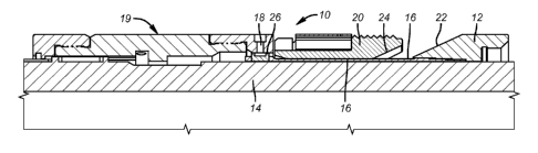
A slip release mechanism provides for undermining the slip cone in the set position of the slips so that the grip of the slips can be released subsequent to allowing the cone ramp to flex. The slips can be pulled back down the cone ramp as the completion of the same motion that undermines the support for the cone.
L'invention concerne un mécanisme de libération de coin de retenue permettant de saper le cône de coin de retenue dans la position fixée des coins de retenue de sorte que l'adhérence des coins de retenue puisse être libérée après avoir laissé la rampe de cône se fléchir. Les coins de retenue peut être retirés vers le bas de la rampe de cône à la fin du même mouvement qui sape le support pour le cône.
Note: Claims are shown in the official language in which they were submitted.
Note: Descriptions are shown in the official language in which they were submitted.
For a clearer understanding of the status of the application/patent presented on this page, the site Disclaimer , as well as the definitions for Patent , Administrative Status , Maintenance Fee and Payment History should be consulted.
| Title | Date |
|---|---|
| Forecasted Issue Date | 2018-07-24 |
| (86) PCT Filing Date | 2015-04-04 |
| (87) PCT Publication Date | 2015-10-22 |
| (85) National Entry | 2016-09-29 |
| Examination Requested | 2016-09-29 |
| (45) Issued | 2018-07-24 |
There is no abandonment history.
Last Payment of $277.00 was received on 2024-03-20
Upcoming maintenance fee amounts
| Description | Date | Amount |
|---|---|---|
| Next Payment if standard fee | 2025-04-04 | $347.00 |
| Next Payment if small entity fee | 2025-04-04 | $125.00 |
Note : If the full payment has not been received on or before the date indicated, a further fee may be required which may be one of the following
Patent fees are adjusted on the 1st of January every year. The amounts above are the current amounts if received by December 31 of the current year.
Please refer to the CIPO
Patent Fees
web page to see all current fee amounts.
| Fee Type | Anniversary Year | Due Date | Amount Paid | Paid Date |
|---|---|---|---|---|
| Request for Examination | $800.00 | 2016-09-29 | ||
| Application Fee | $400.00 | 2016-09-29 | ||
| Maintenance Fee - Application - New Act | 2 | 2017-04-04 | $100.00 | 2016-09-29 |
| Maintenance Fee - Application - New Act | 3 | 2018-04-04 | $100.00 | 2018-03-06 |
| Final Fee | $300.00 | 2018-06-11 | ||
| Maintenance Fee - Patent - New Act | 4 | 2019-04-04 | $100.00 | 2019-03-26 |
| Maintenance Fee - Patent - New Act | 5 | 2020-04-06 | $200.00 | 2020-04-01 |
| Maintenance Fee - Patent - New Act | 6 | 2021-04-06 | $204.00 | 2021-03-23 |
| Maintenance Fee - Patent - New Act | 7 | 2022-04-04 | $203.59 | 2022-03-23 |
| Maintenance Fee - Patent - New Act | 8 | 2023-04-04 | $210.51 | 2023-03-21 |
| Maintenance Fee - Patent - New Act | 9 | 2024-04-04 | $277.00 | 2024-03-20 |
Note: Records showing the ownership history in alphabetical order.
| Current Owners on Record |
|---|
| BAKER HUGHES INCORPORATED |
| Past Owners on Record |
|---|
| None |

