Note: Descriptions are shown in the official language in which they were submitted.
CA 02945061 2016-10-06
1
GRINDING ROLLER COMPRISING INSERTS OF INCREASED MASSIVENESS
Field of the Invention
[0001] The present invention relates to grinding rollers produced by
casting in the
technical field of foundry. These rollers are used in vertical axis crushers
for grinding
various materials, including coal, cement raw meal, clinker or slag. The
invention more
particularly relates to grinding rollers comprising inserts with higher
massiveness moduli
than those of the state of the art, optionally reinforced with ceramic grain
agglomerates
which can be infiltrated during casting.
State of the Art
[0002] Application EP 1 570 905 A1 discloses a grinding roller for
a vertical axis
crusher comprising inserts with a low massiveness modulus (<2.5). This
document
emphasizes the various problems encountered during operation with bimetal
grinding
rollers comprising hard inserts in cast iron with high chromium content,
embedded in a
metal matrix of ductile cast iron. In this document, the inserts are spaced
relatively to each
other. This space is filled with ductile cast iron during the casting of the
grinding roller,
which generates a tab blocking the inserts against each other. During
operation, these
tabs, which are not very wear-resistant, become recessed, forming grooves
between the
inserts, which widen gradually as one approaches the center of the grinding
roller (see
Fig. 3).
[0003] Document US 5,238,046 has the same drawbacks. Indeed, each
insert
comprises on at least one of its longitudinal flanks protruding ribs so as to
form a space
between two juxtaposed inserts. During the working of the roller, a
preferential wear of the
ductile alloy comprised in the space is achieved, resulting in the formation
of grooves
between the inserts.
Definitions
[0004] In the foundry industry, the massiveness modulus is measured by the
ratio
of the volume to the surface. It is denoted by V/S. This value, universally
used in the
foundry industry, is among others taken into account in the calculation of the
feeding of
the cast parts since, in order to obtain a sound part, the feeder should have
a V/S ratio
greater than that of the part to be cast.
[0005] The value of the modulus V/S depends on the selection of the adopted
length unit.
CA 02945061 2016-10-06
2
The calculation may be illustrated by the simple example of a cube of side
"a".
In this case, the V/S = a3/(6 a2), that is a/6.
If the V/S is expressed in meters for a cube with a side of one meter: a/6
becomes 1/6 =
0.166 m.
If the V/S is expressed in centimeters: a/6 becomes 100/6 = 16.6 cm.
In the description of the present invention, the modulus V/S will always be
expressed in
centimeters.
Aims of the invention
[0006] The aim of the present invention is to limit the drawbacks of the
state of the
art by reducing as much as possible the presence of grooves formed by the
interstices
between the inserts of a grinding roller. In order to reduce this number of
grooves, the size
and the massiveness modulus of these inserts have to be increased. With more
massive
inserts, the latent heat available during casting will therefore be higher and
will allow
easier infiltrations of thicker ceramic reinforcements which can be
infiltrated. As a
corollary, the invention therefore makes it possible to increase the thickness
of the
ceramic reinforcement of the insert. By improving the infiltration conditions
of the
reinforcement by the casting metal, it is possible to use thicker
reinforcements which in
turn improve the wear resistance of the assembly.
Features of the invention
[0007] The present invention discloses a grinding roller for
vertical axis crushers,
produced by foundry casting, said roller comprising inserts with a massiveness
modulus
V/S comprised between 3 and 5 cm, preferably between 3.2 and 4.5 cm, said
inserts
being embedded in a metal matrix consisting of ductile cast iron or steel.
[0008] According to preferred embodiments, the invention comprises
at least one
or one combination of the following features:
- the grinding roller comprises inserts with a massiveness
modulus V/S
comprised between 3.4 and 4 cm;
- the inserts are positioned against each other, only leaving intermittent
recesses between two inserts and making it possible, during casting, to
generate a binding element of the bolt type improving the fixation of the
insert in the metal matrix;
- the binding element of the bolt type comprises undercuts;
- the inserts are not placed parallel to the axis of rotation of said
roller, but
form an angle of less than 45 with this axis;
CA 02945061 2016-10-06
3
- the inserts have a curvature along their longitudinal axis;
- the inserts have an "S" shape along the longitudinal axis;
- the insert comprises one or several ceramic reinforcements which can be
infiltrated by the casting metal;
- said
reinforcement ceramic is selected from among alumina, zirconia,
alumina-zirconia, metal nitrides, metal carbides and borides or mixtures
thereof.
[0009]
The present invention also discloses a vertical axis crusher comprising a
grinding roller according to the invention.
Short description of the figures
[0010]
Fig. 1 illustrates, according to the state of the art, a section of a vertical
crusher in operation comprising several grinding rollers.
[0011]
Fig. 2a illustrates a three-dimensional view of a grinding roller according to
the state of the art with inserts with a low massiveness modulus and spaces
between the
inserts.
[0012]
Fig. 2b shows a three-dimensional view of an insert with a low
massiveness modulus comprising spacing protrusions according to the state of
the art.
[0013]
Fig. 3 shows, by means of a sectional view, the space remaining between
two adjacent inserts according to the state of the art and the possibility of
forming
increasingly wide grooves between the inserts as the grooves become deeper.
[0014]
Fig. 4 illustrates a three-dimensional view of an insert with a low
massiveness modulus with a ceramic reinforcement and comprising spacers
according to
the state of the art.
[0015] Fig. 5
shows the comparative curves of the number of inserts in the case of
inserts according to the state of the art (V/S < 2.8 cm, squares in the graph)
and of inserts
according to the invention (V/S > 3 cm, rhombuses in the graph). The number of
inserts is
reduced in the grinding rollers according to the invention.
[0016]
Fig. 6a shows a sectional view of two inserts according to the invention
arranged side by side with spacing protrusions making it possible to maintain
a minimum
distance between two inserts. According to the invention, the number of
grooves is limited
by the increase in the massiveness of the insert.
[0017]
Fig. 6b illustrates a three-dimensional view of the insert illustrated in Fig.
6a.
[0018] Fig. 7a
shows a sectional view of two inserts with a ceramic reinforcement
according to the invention placed against each other with an intermittent
recess.
CA 02945061 2016-10-06
4
[0019] Fig. 7b illustrates a three-dimensional view of one of the
two inserts in Fig.
7a where the intermittent recess may be viewed. This recess will allow, during
casting, the
formation of a binding element similar to a bolt with undercuts making it
possible to
improve the fixation of the insert in the metal matrix. The insert also shows
the positioning
of a ceramic reinforcement which can be infiltrated by the casting metal
increasing the
wear resistance.
[0020] Figs. 8a and 8b illustrate the same embodiment of the
invention as the one
in Figs. 7a and 7b, however with an insert curved in the direction of its
longitudinal axis
forming an S >>. This S-shaped >> alternative allows the groove between
the inserts not
to encounter, during grinding, the material to be ground frontally and
according to an
angle of less than 900
.
[0021] Fig. 9 illustrates the same roller as the one in Fig. 2a but
with inserts with a
higher massiveness modulus according to the invention.
[0022] Fig. 10a shows an insert according to the state of the art
as used in a roller
for an LM46/4 Loesche crusher, the comparative test results of which are
illustrated in
Table 1. Fig. 10b illustrates a section along B-B.
[0023] Figs. 11a and 12a show inserts according to the invention as
used in a
roller for an LM46/4 Loesche crusher, the test results of which are also
illustrated in
Table 1. Figs. llb and 12b respectively illustrate sections along B-B.
[0024] Fig. 13a shows a three-dimensional view of an insert according to
one of
the preferred embodiments of the present invention. In Fig. 13b, two of these
inserts are
placed against each other only leaving an intermittent recess with a variable
diameter
along a radial direction on the grinding roller. The recess will allow, during
casting, the
formation of a binding element of the bolt type with undercuts. Here, the
insert also
comprises a ceramic reinforcement which can be infiltrated by the casting
metal.
[0025] Fig. 14 illustrates a three-dimensional view of an
alternative of an insert
which may be used in the roller according to the invention, wherein the recess
is located
on the lateral face in the axial direction of the insert. This recess will
make it possible,
during casting, to generate a binding element in the axial direction of the
grinding roller. A
ceramic reinforcement which can be infiltrated by the casting metal is also
present in this
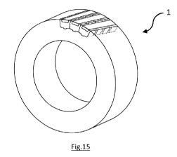
embodiment.
[0026] Figs. 15 and 16 illustrate an embodiment of the invention
wherein the
inserts are not positioned parallel to the axis of rotation of the grinding
roller, but form an
angle of less than 45 with this axis. This type of arrangement has the
advantage that the
groove between the inserts is presented obliquely during grinding of the
material to be
CA 02945061 2016-10-06
ground, which deteriorates less the surface of the grinding roller and
therefore extends the
lifetime of the latter.
[0027] Caption
5 1. Grinding roller.
2. Insert consisting of a composite or metal element that is highly wear-
resistant,
placed on the periphery of the grinding roller.
3. Recesses left between the inserts making it possible to generate a
binding
element made by the casting metal. The binding element will comprise a sort of
bolt which may comprise undercuts.
4. The metal matrix formed by the casting metal consisting of cast iron or
steel and
making up the structure of the roller.
5. A ceramic reinforcement or a reinforcement made of an agglomerate of
ceramic
grains located in the insert, also called a cake , padding >> or wafer
>>.
6. A
vertical axis crusher which comprises the grinding roller; this is the wheel
which
crushes the material on the table of the crusher.
Detailed description of the invention
[0028]
The grooves between the inserts 2 of a grinding roller 1 form a preferential
wear location which is not only detrimental to the lifetime of the grinding
roller 1, but also
to the efficiency of the grinding and to the quality of the ground product.
These grooves
may also be a source of undesirable vibrations during operation of the crusher
6. The
wear is further enhanced in the case of inserts reinforced by ceramics which
can be
infiltrated 5, since upon its creation, the groove weakens the edges of the
insert 2, the
optional ceramic reinforcement 5 of which then tends to crumble and to be worn
out more
rapidly.
[0029]
The thicker the insert 2 is, the better the wear resistance in operation will
be and the thicker its optional ceramic reinforcement which can be infiltrated
5 may be. A
thick ceramic reinforcement 5 will nevertheless be more difficult to
infiltrate with the liquid
metal during casting.
[0030]
The infiltration depth depends on the available latent heat and therefore on
the amount of liquid metal that is available for achieving infiltration. In
the inserts of the
state of the art with a low massiveness modulus, the amount of metal available
for a given
volume of the insert is insufficient for properly infiltrating a ceramic
reinforcement beyond
a thickness of about 50 mm.
CA 02945061 2016-10-06
6
=
[0031] The ceramic reinforcement which can be infiltrated 5 is
sometimes called a
wafer or further a padding or a cake and generally consists of an
agglomerate of
ceramic grains leaving interstices so as to let the casting metal penetrate
therein. To one
skilled in the art it is well known. In terms of composition, without
pretending to be
exhaustive, oxides such as alumina, zirconia, alumina-zirconia, silica or
further metal
nitrides, metal carbides such as titanium carbide or tungsten carbide, borides
or mixtures
of these various constituents are generally used.
[0032] The massiveness modulus of the insert is therefore directly
related to the
infiltration capacity of the ceramic reinforcement which can be infiltrated 5
of the insert 2
by the casting metal 4. The greater the total surface area of the insert with
respect to the
volume of the insert, the more the casting metal tends to cool in contact with
this surface.
Therefore, the higher the volume/surface ratio is, the longer the metal
remains hot and the
easier the infiltration of the ceramic reinforcement 5 is.
[0033] In the design of a grinding roller 1 for a vertical crusher
6 produced by
foundry casting according to the state of the art, the number of inserts
placed on the
perimeter of the grinding roller 1 is generally determined empirically by the
dimension of
the insert in order to obtain sufficient mechanical strength of the operating
roller (see Fig.
5).
[0034] In the insert according to the state of the art, the
thickness of the ceramic
reinforcement 5 is set to a value of less than about 50 mm so as to guarantee
good
infiltration during casting. The lengths of the insert 2 and of the ceramic
reinforcement 5
are approximately equal to the width of the grinding roller 1. The width of
the ceramic
reinforcement 5 generally corresponds to about the width of the insert (see
Fig. 4).
[0035] According to these requirements, the number of inserts based
on the outer
diameter of the roller is given by the upper curve of Fig. 5. In this design,
the inserts
placed in the grinding rollers have a V/S ratio comprised between 1 and 2.8 cm
(see Fig.
2a).
[0036] In order to meet the objectives of the present invention,
the V/S ratio of the
inserts should be comprised between 3 and 5 cm, preferably between 3.2 and 4.5
cm and
more preferably between 3.4 and 4 cm.
[0037] Various embodiments are possible within the scope of this
invention. The
figures show a series of embodiments of the invention for a roller of the same
diameter
and wherein the dimensions of the insert correspond to a massiveness modulus
V/S
between 3 and 5 cm.
[0038] Fig. 13a shows an insert 2 designed according to a preferred
embodiment
of the invention. It has on the lateral faces cylindrical recesses 3 where
concave portions
CA 02945061 2016-10-06
7
and convex portions alternate. During the casting of the metal making up the
structure of
the roller 1, the recesses 3 are filled with metal and the shape alternations
of the recess 3
make it possible to generate binding elements of the bolt type with undercuts
allowing a
permanent fixation of the inserts 2 in their metal matrix 4. They secure the
inserts 2 with
the structure of the roller 1.
[0039] The insert 2 generally comprises a protrusion of small
thickness on the
lower face, thereby suppressing the risk of sliding in the radial direction of
the roller 1. This
protrusion of small thickness may among others appear as a dovetail ensuring
the
anchoring, as notably illustrated in Fig. 11b.
[0040] Figs. 11 and 12 illustrate solutions which differ from each other by
the
contemplated thickness of the ceramic reinforcement 5, considering the
significance of the
stresses encountered during operation.
[0041] The embodiment of the invention according to Figs. 13a and
13b is used
when it is necessary to increase the thickness of the ceramic reinforcement 5
in the insert
2 beyond 50 mm in order to obtain increased wear resistance, but it also gives
the
possibility of benefiting from all the advantages mentioned above. It is
particularly suitable
for rollers of large diameter.
[0042] Certain undulated forms of the inserts, g S-shaped >> forms
for example,
illustrated in Figs. 8a and 8b, generate grooves of the same shape between the
inserts
during wear and give the possibility of mitigating the shock generated by this
groove by
means of the gradual encounter of the latter with the bed of material to be
ground. This
reduces the risk of vibrations. The examples of shapes given in the present
description
are non-limiting; other geometrical shapes may of course be contemplated and
are part of
the present invention.
Examples
[0043] Three grinding rollers comprising three types of different
inserts were
experimentally tested on an LM46/4 Loesche crusher. The three types of inserts
2 are
illustrated in Figs. 10, 11 and 12. The inserts are cast in cast iron of the
type with 3% by
weight of carbon and 16% by weight of chromium (U19) in order to be then
integrated
(embedded) in a grinding roller, the metal matrix of which consists of cast
iron with
spheroidal graphite of the GGG40 type. The ground material is cement raw meal.
The
inserts 2 comprise ceramic reinforcements which can be infiltrated 5 of the
alumina-
zirconia type. The diameter of the rollers is 2,000 mm in the 3 cases. The
number of
operating hours represents the lifetime of the rollers.
The results of the tests are given in Table 1 below.
CA 02945061 2016-10-06
8
Table 1
EXAMPLES NUMBER V/S OF Ceramic Number Production
Improvement
OF OF INSERTS reinforcement of (tons) in %
INSERTS INSERTS (cm) dimensions operating
(mm) hours
Comparative
inserts
according to
73 2.6 560x75x48 10,000 3,050,000 Reference
the prior art
Figs. 10a
and b
Inserts
according to
the invention 47 3.3 560x130x60 12,000
3,700,000 +20%
Figs. 11a
and b
Inserts
according to
the invention 47 3.5 560x130x90 15,000
4,575,000 +50%
Figs. 12a
and b