Note: Descriptions are shown in the official language in which they were submitted.
CA 02945094 2016-10-13
278630
TURBINE SLOTTED ARCUATE LEAF SEAL
BACKGROUND OF THE INVENTION
TECHNICAL FIELD
[0001] The present invention relates generally to gas turbine engine turbine
flowpath
seals and, more specifically, to arcuate leaf seals and mounting thereof.
BACKGROUND INFORMATION
[0002] Gas turbine engine high pressure turbines typically include turbine
nozzles
separately manufactured and assembled into position in the engine.
Accordingly, gaps
are necessarily provided therebetween for both assembly purposes as well as
for
accommodating differential thermal expansion and contraction during operation
of the
engine. Gaps between these stationary stator components are suitably sealed
for
preventing leakage therethrough. In a typical high pressure turbine nozzle, a
portion of
the compressor air is bled and channeled through the nozzle vanes for cooling
thereof.
The use of bleed air reduces the overall efficiency of the engine and,
therefore, is
minimized whenever possible. The bleed air is at a relatively high pressure
greater than
the pressure of the combustion gases flowing through the turbine nozzle and,
therefore,
would leak into the exhaust flowpath without providing suitable seals between
the stator
components.
[0003] Arcuate leaf seals are particularly useful to seal these gaps in the
turbine
flowpaths. The leaf seals typically used in such applications are arcuate and
disposed end
to end around the circumference of the stator components which are segmented.
For
example, the radially outer band of the turbine nozzle includes axially spaced
apart
forward and aft rails. These rails extend radially outwardly, with the aft
rail abutting a
complementary surface on the adjoining shroud or shroud hanger, for providing
a
primary friction seal therewith. The leaf seal provides a secondary seal at
this junction
1
CA 02945094 2016-10-13
278630
and bridges a portion of the aft rail and the shroud hanger for example.
Circumferential
seals or arcuate leaf seals typically require a large space to effectively
seal and cover a
large range of relative motion between the two surfaces to be sealed.
[0004] In order to assemble and mount the leaf seals to the aft rail, each
leaf seal
typically includes mounting holes at opposite circumferential ends thereof
through which
are mounted corresponding mounting pins. Corresponding springs such as leaf
springs
are also used at respective ones of the mounting pins for pre-loading the
loosely
supported leaf seals against the aft rail and the shroud hanger.
[0005] In order to support the leaf seals, leaf springs, and mounting pins,
the outer band
may include a plurality of circumferentially spaced apart, radially extending
tabs spaced
axially from the aft rail. A recess is formed between the tabs and the aft
rail in which the
leaf seal and leaf spring are disposed. The tabs include forward holes aligned
with
corresponding aft holes which extend into but not all the way through the aft
rail. The
mounting pins are inserted through holes in the tabs, leaf spring, leaf seal,
and into the aft
rail and then fixedly joined thereto by tack welding heads of the mounting
pins to the
corresponding tabs.
[0006] To accommodate relative movement between the nozzles and mating
hardware,
the leaf seals are designed to float about the mounting pins that are firmly
attached to the
nozzle segment. During engine operation, pressure differential between the
cooling
supply air and the flowpath air holds the seal against the mating hardware.
Springs are
used to provide positive contact at the sealing surface when pressure loading
across the
seal is low.
[0007] This mounting arrangement for the leaf seals is relatively complex and
subject to
damage during the assembly process in view of the relatively close quarters in
this
region. A smaller and less complex leaf seal mounting system is desired for
simplifying
the manufacture and assembly thereof and eliminating tack welding of the
mounting pins
and drilling of a blind hole into the aft rail or flange. A smaller and less
complex leaf
2
CA 02945094 2016-10-13
278630
seal mounting system is desired to accommodate tight and small turbine stator
assemblies.
SUMMARY OF THE INVENTION
[0008] A gas turbine engine arcuate leaf seal assembly includes an arcuate
leaf seal
extending radially and circumferentially between adjacent first and second
turbine
components. The leaf seals are operable for preventing or inhibiting leakage
between
first and second fluid volumes through a gap between the first and second
turbine
components and upper and lower leaf seal portions of the arcuate leaf seals
are disposed
in radially spaced apart arcuate leaf seal upper and lower grooves in the
first and second
turbine components respectfully.
[0009] The leaf seal may include an arcuate body and at least one
circumferential
retention tab extending radially away from the arcuate body. The retention tab
may be
disposed in a notch in a forward or aft annular wall or an aft annular wall of
the upper or
lower grooves. The retention tab may be sufficiently flexible for the leaf
seal to engage
seal edges on upper and lower faces of the upper and lower grooves
respectively during
the entire range of engine operation. The leaf seal may have a thickness in a
range of
from 3 mils to 35 mils. The leaf seal may be made of a material with torsional
stiffness
in a range between 0.015 lb/in and 0.15 lb/in.
[0010] One of the turbine nozzle upper and lower components may include or be
made of
a ceramic matrix composite material.
[0011] The adjacent first and second turbine components may be radially
adjacent
turbine nozzle upper and lower components respectively or the adjacent first
and second
turbine components being axially adjacent.
[0012] A segmented turbine nozzle may include a ring of turbine nozzle
segments
circumscribed about an axis. Each of the turbine nozzle segments includes a
radially
inner support ring segment, a radially outer support ring segment, and at
least one nozzle
3
CA 02945094 2016-10-13
278630
fairing supported and disposed therebetween. A strut is coupled to and
operable for
carrying loads between the inner and outer support ring segments. The nozzle
fairing
includes radially spaced apart inner and outer band segments and a fairing
airfoil or vane
extending radially therebetween. At least one gas turbine engine arcuate leaf
seal
assembly including an arcuate leaf seal extends radially and circumferentially
between
the inner band segment and the inner support ring segment. Upper and lower
leaf seal
portions of the arcuate leaf seal are disposed in radially spaced apart
arcuate leaf seal
upper and lower grooves in the inner band segment and the inner support ring
segment
respectfully.
[0013] The turbine nozzle may further include forward and aft turbine leaf
seal
assemblies including the at least one gas turbine engine arcuate leaf seal
assembly, the
forward and aft turbine leaf seal assemblies positioned at forward and aft
ends of the
nozzle segment respectfully between the inner support ring segment and the
inner band
segment of the fairing, each of the forward and aft turbine leaf seal
assemblies including
an arcuate leaf seal extending radially and circumferentially between the
inner band
segment and the inner support ring segment, each of the forward and aft
turbine leaf seal
assemblies including radially spaced apart arcuate leaf seal upper and lower
grooves in
upper and lower flanges of the inner band segment and the inner support ring
segment
respectively, and upper and lower leaf seal portions of each of the arcuate
leaf seals of
each of the forward and aft turbine leaf seal assemblies disposed in the
radially spaced
apart arcuate leaf seal upper and lower grooves in the inner band segment and
the inner
support ring segment respectfully.
[0014] An annular cooling air plenum including flow cavities disposed in the
inner
support ring segments may be in flow communication with the hollow fairing
airfoils.
The nozzle fairing may be made of a ceramic matrix composite material.
4
CA 02945094 2016-10-13
278630
BRIEF DESCRIPTION OF THE DRAWINGS
[0015] The invention, in accordance with preferred and exemplary embodiments,
is more
particularly described in the following detailed description taken in
conjunction with the
accompanying drawings in which:
[0016] FIG. 1 is a schematical illustration of an exemplary aircraft turbofan
gas turbine
engine including a turbine nozzle with an exemplary embodiment of an arcuate
turbine
slotted leaf seal assembly.
[0017] FIG. 2 is a side or circumferential view illustration of an exemplary
embodiment
of a slotted leaf seal mounting assembly for use in the turbine nozzle
illustrated in FIG. 1.
[0018] FIG. 3 is an axial view illustration of the exemplary embodiment of the
slotted
leaf seal mounting assembly through 3-3 in FIG. 2.
[0019] FIG. 4 is a perspective view illustration of an exemplary embodiment of
a slotted
leaf seal mounting assembly for use in the turbine nozzle illustrated in FIG.
1.
[0020] FIG. 5 is a schematical view illustration of the slotted leaf seal
illustrated in FIG.
2 in a sealed position.
[0021] FIG. 6 is a perspective view illustration of an exemplary turbine
nozzle for use in
the engine illustrated in FIG. 1.
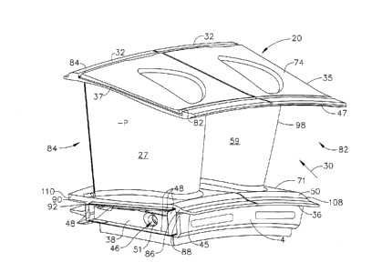
[0022] FIG. 7 is an enlarged perspective view illustration of a turbine nozzle
segment in
the exemplary turbine nozzle illustrated in FIG. 6.
[0023] FIG. 8 is an exploded view illustration of the turbine nozzle segment
illustrated in
FIG. 7.
[0024] FIG. 9 is a perspective view illustration of a turbine fairing in the
turbine nozzle
segment illustrated in FIG. 8.
CA 02945094 2016-10-13
278630
[0025] FIG. 10 is a circumferentially oriented perspective view illustration
of a turbine
fairing in the turbine nozzle segment illustrated in FIG. 8.
[0026] FIG. 11 is an enlarged perspective view illustration of an aft leaf
seal mounting
assembly illustrated through 11-11 in FIG. 10.
[0027] FIG. 12 is an enlarged perspective view illustration of a forward leaf
seal
mounting assembly illustrated through 11-11 in FIG. 10.
[0028] FIG. 13 is a perspective view illustration of an inner support ring
segment with a
single turbine fairing removed in the turbine nozzle segment illustrated in
FIG. 8.
[0029] FIG. 14 is a sectional side view illustration of spline seals in a side
of the inner
support ring segment in the turbine nozzle segment illustrated in FIG. 8.
DESCRIPTION
[0030] Illustrated schematically in FIG. 1 is an exemplary aircraft turbofan
gas turbine
engine 10 which is axisymmetrical about a longitudinal or axial centerline
axis 12. The
engine 10 includes in serial flow communication, a fan 14, multistage axial
compressor
16, annular combustor 18, a high pressure turbine 19 including a high pressure
turbine
nozzle 20 upstream of and followed by a single stage high pressure turbine
rotor 22, and
one or more stages of low pressure turbine nozzles 24 and rotors 26. The high
pressure
rotor 22 is joined to the compressor 16 by a first shaft 21 and the low
pressure rotor 26 is
joined to the fan 14 by a coaxial second shaft 25. During operation, ambient
air 8 flows
downstream through the fan 14, the compressor 16 from where it exits as
compressed air
28 and is then flowed into the combustor 18. The compressed air 28 is mixed
with fuel
and ignited in the combustor 18 generating hot combustion gases 30 which flow
downstream through turbine stages which extract energy therefrom for powering
both the
fan 14 and the compressor 16. The various stator and rotor components of the
turbines
downstream from the combustor 18 define a turbine flowpath 27 which channels
the hot
combustion gases therethrough for discharge from the engine. Downstream of and
6
CA 02945094 2016-10-13
278630
adjacent to the high pressure turbine nozzle 20 is the high pressure turbine
rotor 22. The
high pressure turbine rotor 22 may take any conventional form having a
plurality of
circumferentially spaced apart turbine blades 23 extending radially outwardly
from a
rotor disk for extracting energy from the gases 30 and powering the compressor
16.
[0031] A portion of the compressed air 28 is bled from the compressor 16 and
used as
cooling air 29 which is channeled to various parts of the turbines such as the
high
pressure nozzle 20 to provide cooling thereof. Some of the cooling air 29 is
channeled
around and through the high pressure turbine nozzle 20 at a substantially high
pressure
+P compared to the low pressure -P of the combustion gases 30 flowing through
the
turbine flowpath 27 in the high pressure turbine nozzle 20 during engine
operation.
[0032] Turbine components are often manufactured in arcuate segments and then
assembled together in the engine 10 forming axially adjacent turbine
components such as
a turbine shroud segment 40 located adjacent to and downstream of a turbine
nozzle
segment 32 as illustrated in FIGS. 1, 6, and 16. Various joints or gaps are
provided
between annular assemblies of arcuate segments which must be suitably sealed
for
preventing leakage of the high pressure +P cooling air 29 into the turbine
flowpath 27
through which the low pressure -P combustion gases 30 flow during engine
operation.
The use of bleed air for cooling turbine components necessary decreases the
overall
efficiency of the engine 10 and its use is minimized. It is desirable to
provide suitable
seals between the stationary or stator turbine components for reducing to a
minimum the
amount of cooling air leakage into the exhaust flowpath for increasing
efficiency of the
engine.
[0033] Schematically illustrated in FIGS. 1-3 is an arcuate first turbine
component 4
cooled with the cooling air 29 at a relatively high pressure +P compared to
the relatively
low pressure -P of the combustion gases 30 channeled through the first turbine
component 4 of the nozzle 20. An arcuate turbine slotted leaf seal assembly 33
may
include an arcuate leaf seal 52 extending radially and circumferentially
between a second
turbine component 6 and the first turbine component 4 of the nozzle 20 to
prevent or
7
CA 02945094 2016-10-13
278630
inhibit leakage of the cooling air 29 into the turbine flowpath 27 through a
gap 15
between the first and second turbine components 4, 6.
[0034] The first and second turbine components 4, 6 are adjacent and include
first and
second portions 114, 116 respectfully that are spaced radially apart with
respect to the
axis 12 and include radially spaced apart first and second or arcuate leaf
seal upper and
lower grooves 9, 11 or slots. Upper and lower leaf seal portions 54, 56 of the
arcuate leaf
seal 52 are disposed in the upper and lower slots or grooves 9, 11 in the
first and second
portions 114, 116 respectfully. The arcuate leaf seal 52 is substantially
fully disposed in
the upper and lower grooves 9, 11.
[0035] The adjacent first and second turbine components 4, 6 may be turbine
nozzle
radially inner and outer or upper and lower components 94, 96 used in arcuate
segments
in the engine 10 such as the turbine nozzle segment 32 illustrated in FIGS. 6-
9. The
upper and lower components 94, 96 may include arcuate leaf seal upper and
lower
grooves 9, 11 in which upper and lower leaf seal portions 54, 56 respectfully
of the
arcuate leaf seal 52 are disposed. The arcuate leaf seal 52 is substantially
fully disposed
in the upper and lower grooves 9, 11.
[0036] The arcuate leaf seal 52, as illustrated in FIGS. 2-5 and 8, includes
an arcuate
body 58 and at least one circumferential retention tab 61 extending radially
away from
the arcuate body 58. The circumferential retention tab 61 is disposed in and
engages a
notch 63 of a forward annular wall 72 as illustrated in FIG. 3 or an aft
annular wall 73 of
the upper or lower grooves 9, 11 as illustrated in FIG. 4. The arcuate leaf
seal 52 is
captured in the upper and lower grooves 9, 11 as particularly illustrated in
FIGS. 2 and 4.
A locus of contact points 17 between the arcuate leaf seal 52 and contact
walls 102 of
the upper and lower grooves 9, 11 serve to create a seal between two fluid
volumes
denoted herein as first and second fluid volume 57, 59 as illustrated in FIG.
5.
[0037] Referring to FIGS. 6-9, the first fluid volume 57 is illustrated herein
as a cooling
air plenum 46 which receives the cooling air 29 channeled through
circumferentially
8
CA 02945094 2016-10-13
278630
spaced apart hollow stator airfoils 39 of the high pressure turbine nozzle 20
at a
substantially high pressure +P. The second fluid volume 59 is illustrated
herein as the
combustion gases 30 in the turbine flowpath 27 through the high pressure
turbine nozzle
20 which operates at the low pressure -P during engine operation.
[0038] Illustrated in FIGS. 2-5 is the arcuate leaf seal 52 and the contact
points 17 which
divide the two fluid volumes or flowpaths. The relative position of the upper
groove 9 to
the lower groove 11 may be in a range in both the axial or horizontal
direction 60 and the
radial or vertical direction 62. Due to this range of relative positioning,
the nature of the
contact points between the seal and the two grooves may be variable. In the
position
illustrated in FIG. 4, the leaf seal 52 contacts an upper face 64 of the upper
groove 9, and
a lower face 66 of the lower groove 11. The surface contact on both of these
faces
creates the locus of contact points 17 which separate the two fluid volumes.
[0039] The degree of leakage between these two fluid volumes is dependent upon
the
conformance of the leaf seal to small surface irregularities on both upper and
lower
contact surfaces 68, 69 of the upper and lower faces 64, 66 respectively, and
upon the
elasticity of the leaf seal 52 and ability to conform under a pressure load
generated by a
differential pressure. The differential pressure is between the high pressure
+P in the first
fluid volume 57 or the chamber containing the cooling air 29 and the low
pressure -P in
the second fluid volume 59 or the turbine flowpath 27 in the high pressure
turbine nozzle
20 during engine operation.
[0040] The contact points 17 are on smaller surface areas of the upper and
lower contact
surfaces 68, 69 of the upper and lower faces 64, 66 respectively in some other
axially
offset positions of the upper and lower grooves 9, 11. Illustrated in FIG. 5
is an example
of a large horizontal offset in the axial or horizontal direction 60 between
the upper and
lower grooves 9, 11. The contacts along the contact points 17 are edge
contacts as
illustrated in FIG. 5 for a horizontal offset 67 between the upper and lower
grooves 9, 11.
The upper leaf seal portion 54 of the leaf seal 52 contacts the upper face 64
of the upper
9
CA 02945094 2016-10-13
278630
groove 9 while the lower leaf seal portion 56 of the leaf seal contacts a
groove edge 76 on
the lower face 66 of the lower groove 11.
[0041] Referring to FIGS. 2-5, the circumferential retention tab 61 is
flexible so as to
allow engagement of the leaf seal 52 with seal edges on upper and lower faces
64, 66 of
the upper and lower grooves 9, 11 respectively during the entire range of
engine
operation. The arcuate body 58 of the arcuate leaf seal 52 is able to conform
to the upper
and lower grooves 9, 11. The arcuate body 58 may have a range of thickness and
stiffness as may the leaf seal 52. The leaf seal 52 including the arcuate body
58 may
have a thickness T in a range of from 3 mils to 35 mils and may use materials
with
torsional stiffness in a range between 0.015 lb/in and 0.15 lb/in.
[0042] In the exemplary engine illustrated in FIG. 1, one embodiment of the
turbine leaf
seal assembly 33 is located between the turbine flowpath 27 through the high
pressure
turbine nozzle 20 and cooling air 29 flowing within static structure of the
high pressure
turbine nozzle 20. The leaf seal assembly 33 may be used and adapted for other
analogous sealing applications within the engine 10 and, in particular,
between the
various turbine stator components thereof. One example of a stationary or
stator turbine
arcuate component is the turbine nozzle segment 32 of the annular high
pressure turbine
nozzle 20 illustrated in FIGS. 6-8 and 16. Circumferentially adjoining nozzle
segments
32 are bolted or otherwise joined together to form the full ring annular high
pressure
turbine nozzle 20 as illustrated in FIGS. 6 and 9.
[0043] Illustrated in FIGS. 6-10, is one exemplary high pressure segmented
turbine
nozzle 20 including a ring of turbine nozzle segments 32 circumscribed about
the axis 12.
The exemplary embodiment of the turbine nozzle 20 and the turbine nozzle
segment 32
illustrated in FIGS. 6-9 was developed for CMC vanes and is disclosed in more
detail in
US Patent Application No. 14/574,472 titled "Ceramic Matrix Composite Nozzle
Mounted With a Strut and Concepts Thereof by Benjamin Scott Huizenga et al.,
filed
December 18, 2014 and incorporated herein by reference.
CA 02945094 2016-10-13
278630
[0044] The turbine nozzle 20 includes segmented annular outer and inner bands
35, 36
and a plurality of airfoils or vanes 75 extending radially therebetween. Each
of the
turbine nozzle segments 32 includes a radially inner support ring segment 45,
a radially
outer support ring segment 47 and at least one nozzle fairing 50 supported and
disposed
therebetween. Extending radially through at least one nozzle fairings 50 is a
strut 70
which carries load from the inner support ring segment 45 to the outer support
ring
segment 47 where load is transferred to a static structure 13 such as an
engine casing and
mechanically supports the nozzle segment 32 as illustrated in FIG. 8. The
nozzle fairing
50 includes radially spaced apart the inner and outer band segments 71, 74 and
a fairing
airfoil 98 therebetween. One particular embodiment of the nozzle fairing 50 is
a CMC
fairing 50 made of a ceramic matrix composite material.
[0045] The strut 70 carries load from the radially inward side of the nozzle
segment 32 at
the inner support ring 38 to the radially outward side at the outer support
ring 37 where
load is transferred to a static structure and mechanically supports the nozzle
fairing 50.
The strut 70 may be connected to at least one of the inner support ring 38 and
the outer
support ring 37 in a variety of manners described herein including by bolting,
fastening,
capturing, combinations thereof and being integrally formed.
[0046] The fairing 50 may be of the single vane type, generally known as a
"singlet" or
may be of the double vane type generally known as a "doublet". These are
merely
exemplary as additional numbers of vanes may be utilized in the nozzle segment
32. The
upper surface of the inner band segment 71 provides one flow surface for
combustion
gas. The lower surface of the outer band segment 74 provides an opposite flow
surface
for the combustion gas. These surfaces define boundaries for flow of
combustion gas
through the nozzle segment 32 with the vane extending therebetween.
[0047] Referring to FIGS. 7-9, disposed above the fairing 50 is the outer
support ring 37
which connects the nozzle segment 32 to a static structure 13. The outer
support ring 37
also extends circumferentially and axially between a forward end 82 and an aft
end 84.
The outer support ring 37 further captures the fairing 50 on the strut 70
between the outer
11
CA 02945094 2016-10-13
278630
support ring 37 and the inner support ring 38. The strut 70 is fastened to the
outer
support ring 37 and connected to the inner support ring 38 to transfer load
through the
nozzle segment 32. The fairing 50 is positioned to float on the strut 70 and
is captured
between the outer support ring 37 and inner support ring 38.
[0048] Circular collars 105, 106 positioned on the inward surface of the inner
support
ring receive the strut 70 providing engagement with the inner support ring and
may be
fastened, according to one embodiment, through a slip-fit pin connection
capturing the
strut 70 in the inner support ring. Flow cavities 51 in the radially inner
support ring
segments 45 together serve as the annular cooling air plenum 46. The annular
cooling air
plenum 46 receives the cooling air 29 channeled through circumferentially
spaced apart
hollow stator airfoils 39 of the high pressure turbine nozzle 20 at a
substantially high
pressure +P. The annular cooling air plenum 46 helps to balance or even out
the flow of
the cooling air 29 and minimize pressure differentials between all the flow
cavities 51.
[0049] The exemplary embodiment of the turbine nozzle segment 32 illustrated
in FIGS.
6-14 include forward and aft turbine leaf seal assemblies 78, 80 positioned at
forward and
aft ends 82, 84 of the nozzle segment 32 between the inner support ring and
the inner
band segment 71 of the fairing 50. Each of the forward and aft turbine leaf
seal
assemblies 78, 80 includes radially spaced apart first and second or arcuate
leaf seal
upper and lower grooves 9, 11 in forward upper and lower flanges 86, 88 and
aft upper
and lower flanges 90, 92 of the inner band segment 71 and the inner support
ring segment
45, respectively. Each of the arcuate leaf seals 52 is trapped in the upper
and lower
grooves 9, 11.
[0050] Referring further to FIGS. 3 and 4, upper and lower leaf seal portions
54, 56 of
the arcuate leaf seal 52 are disposed in the upper and lower grooves 9, 11
respectively.
The arcuate leaf seals 52, as illustrated in FIG. 3, includes an arcuate body
58 and at least
one circumferential retention tab 61 extending radially away from the arcuate
body 58.
The circumferential retention tab 61 is disposed in and engages a notch 63 in
a forward
annular wall 72 or an aft annular wall 73 of the upper or lower grooves 9, 11.
The upper
12
CA 02945094 2016-10-13
278630
and lower grooves 9, 11 and the arcuate leaf seal 52 disposed therein extend
circumferentially all the way across the turbine nozzle segment 32 between
clockwise
and counter-clockwise side edges 108, 110 of the turbine nozzle segment 32.
[0051] Spline seals 48 disposed in spline seal slots 49 are used to seal
between the
circumferentially adjoining nozzle segments 32 as illustrated in FIGS. 7-14.
The spline
seal slots 49 include axially extending upper slots 120 disposed in the inner
band
segments 71 of the nozzle fairings 50 which may be made of a CMC as
illustrated herein.
The spline seal slots 49 further include axially extending lower slots 122
disposed in the
inner support ring segments 45. The spline seal slots 49 also include radially
extending
forward and aft slots 126, 128 disposed in the upper and lower flanges 86, 88
of the inner
band segment 71 and the inner support ring segment 45 respectively. The nozzle
fairing
50 includes radially spaced apart the inner and outer band segments 71, 74 and
a fairing
airfoil 98 therebetween. One particular embodiment of the nozzle fairing 50 is
a CMC
fairing 50 made of a ceramic matrix composite material. The spline seals 48
seal
circumferentially adjacent flow cavities 51 providing sealing therebetween and
sealing
for the annular cooling air plenum 46. The spline seals 48 maintain sealing of
the annular
cooling air plenum 46 between the circumferentially radially inner support
ring segments
45 and continuity thereof between the flow cavities 51.
[0052] While there have been described herein what are considered to be
preferred and
exemplary embodiments of the present invention, other modifications of these
embodiments falling within the scope of the invention described herein shall
be apparent
to those skilled in the art.
13