Note: Descriptions are shown in the official language in which they were submitted.
CA 02945185 2016-10-06
WO 2015/168627
PCT/US2015/028903
PUSH AND PULL MEDICAL DEVICE DELIVERY SYSTEM
BACKGROUND
Field
[00011 The present disclosure relates to delivery systems for implantable
medical devices and, more particularly, relates to delivery systems for
endoluminal
delivery and push-pull positioning of implantable medical devices utilizing
multiple
percutaneous access points.
Discussion of the Related Art
[00021 The use of implantable medical devices in the treatment of diseased
vasculature and other body conduits has become commonplace in the medical
field.
Such devices can be surgically implanted in or delivered endoluminally to the
treatment site. In the latter case, these devices are typically retained in a
compacted
crown diameter along a leading end of a catheter for insertion through a
percutaneous access site. It can be desirable for the catheter to have
sufficient
rigidity to enable a clinician to push the catheter through the single access
point and
traverses the vasculature without bunching or buckling and further allow axial
or
rotational control while positioning the device at the treatment site. On the
other
hand, it is at times desirable for the catheter to have sufficient flexibility
to traverse
tortuous vasculature. In some cases, multiple access sites and/or multiple
catheters
can be used to deliver multiple devices and/or related tools to the treatment
site.
Multiple access sites and catheters may help the healthcare provider to
accomplish
more complicated procedures, but current multiple access site delivery schemes
still
have some weaknesses in delivering medical devices accurately.
[00031 Multiple percutaneous access sites may be useful in the aorta wherein
one access is radial or brachial and the other is iliac or femoral. In the
peripheral
anatomy, a clinician may use a pedal access along with iliac or femoral to
place a
device such as stent, stent-graft or use and control endovascular tools such
as
embolectomy, CTO, Thrombectomy or atherectomy tools. Other potential access
sites include translumbar access to the aorta, transapical access in the heart
to
radial, brachial or femoral, femoral to femoral over the aortic bifurcation,
any venous
1
access, crossing the atrial septum and continuing on to any appropriate
arterial access
site. As has become obvious, any multiple access sites may be envisioned
which,
when traversed by an endoluminal tool, can provide a clinician enhanced perk
procedural control of endoluminal tools and devices. Likewise, the access and
egress
should not be limited to the vascular system. These same benefits apply to
other bodily
systems such as gastrointestinal, cob-rectal, esophageal and biliary. It is
also
envisioned there is benefit in procedures such as bypass grafting wherein the
tools and
devices actually leave the host lumen path and establish an alternate route
and even
wherein there is no host vessel at all, such as in placement of indwelling
electrical
leads for neurostimulation or similar.
[0004] Therefore, it remains desirable to provide a multiple access site
delivery system that facilitates accurate and efficient endoluminal deployment
of
implantable devices and endovascular tools.
SUMMARY
In accordance with an aspect of the disclosure, there is provided a system
for delivery of a medical device, which comprises: a delivery member; and a
medical device disposed about the delivery member and releasably retained in a
delivery configuration for endoluminal delivery of the medical device toward a
treatment site in a human vessel, wherein the delivery member includes an
elongated first portion configured to extend outside of the body from a first
percutaneous access site and an elongated second portion configured to extend
outside the body from a second percutaneous access site to allow positioning
of
the medical device at the treatment site by manipulation of the first portion
and
second portion from outside of the body, wherein a first end of one of the
first and
second portions of the delivery member is configured to be received within a
first
end of the other of the first and second portions of the delivery member.
BRIEF DESCRIPTION OF THE DRAWINGS
[0005] The accompanying drawings are included to provide a further
understanding of the present disclosure and are incorporated in and constitute
a part of
this specification, illustrate embodiments of the present disclosure, and
together with
the description serve to explain the principles of the present disclosure.
2
CA 2945185 2018-02-27
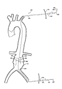
[0006] FIG. 1 shows a schematic representation of human anatomy from the
aortic valve to the iliac vessels.
[0007] FIG. 2 shows a schematic of the human anatomy and the placement of a
guidewire and introducer sheath into the human anatomy.
[0008] FIG. 3A shows a schematic representation of human anatomy with a
first catheter fed through a first access site and out a second access site.
[0009] FIG. 3B shows a schematic representation of human anatomy with a
first catheter protruding from a first access site and a second catheter
protruding
from a second access site with a constrained device on the second catheter
insitu.
[0010] FIG. 4 shows a schematic representation of a device on a second
catheter and the second catheter inside a first catheter prior to at least a
partial
transfer of the device from the second catheter to the first catheter.
[0011] FIG. 5 shows a side view of a device on a second catheter partially
deployed along a first catheter.
2a
CA 2945185 2018-02-27
CA 02945185 2016-10-06
WO 2015/168627
PCMJS2015/028903
[0012] FIG. 6 shows a schematic of human anatomy with a device on a
second catheter partially deployed along a first catheter.
[0013] FIG. 7A shows a schematic of human anatomy with a device partially
deployed from a second catheter to a vessel wall on one end of the device and
constrained by a first catheter on an opposite end of the device and the
device
expanding against a vessel.
[00141 FIG. 7B shows a schematic of human anatomy with a device partially
constrained along a second catheter on one end of the device and partially
deployed
from a first catheter and expanded against a vessel on an opposite end of the
device.
[0015] FIG. 8 shows a schematic of human anatomy with a device deployed
from a second catheter and expanded against a vessel.
[00161 FIG. 9A shows a device constrained along a catheter.
[0017] FIG. 9B shows a catheter with a first larger outer diameter, and a
device constrained along the first larger outer diameter, and a second outer
diameter
less than the first outer diameter.
[0018] FIG. 90 shows a schematic representation of human anatomy with a
first catheter protruding from a first access site and a second access site
with a
constrained device on the first catheter in situ.
[0019] FIG. 10 shows a schematic of human anatomy with a guidewire fed
from a first access site out a second access site.
[00201 FIG. 11 shows a schematic of human anatomy with a guidewire fed
from a first access site out a second access site and the guidewire able to be
manipulated from the first access site and the second access site.
[0021] FIG. 12 shows a schematic of human anatomy with a first catheter fed
through a first access site and through a second access site, and a second
catheter
with a device constrained along the second catheter able to be connected
extracorporeal to the first catheter.
[0022] FIG. 13 shows a schematic of human anatomy with a first catheter
protruding from a first access site and a second catheter protruding from a
second
access site and a device constrained along the second catheter and positioned
at an
implant site by the first catheter and second catheter.
[0023] FIG. 14 shows a schematic of human anatomy with an embolic
protection device and a catheter device positioned near the implant side,
where the
3
CA 02945185 2016-10-06
WO 2015/168627
PCMJS2015/028903
catheter device is manipulated into position via a first catheter connected to
a
second catheter.
DETAILED DESCRIPTION
[0024] Persons skilled in the art will readily appreciate that various aspects
of
the present disclosure can be realized by any number of methods and
apparatuses
configured to perform the intended functions. Stated differently, other
methods and
apparatuses can be incorporated herein to perform the intended functions. It
should
also be noted that the accompanying drawing figures referred to herein are not
all
drawn to scale, but can be exaggerated to illustrate various aspects of the
present
disclosure, and in that regard, the drawing figures should not be construed as
limiting. Finally, although the present disclosure can be described in
connection with
various principles and beliefs, the present disclosure should not be bound by
theory.
[0025] Throughout this specification and in the claims, the term "distal"
refers
to a location that is, or a portion of an endoluminal device (such as a stent-
graft) that
when implanted is, further downstream with respect to blood flow than another
portion of the device. Similarly, the term "distally" refers to the direction
of blood flow
or further downstream in the direction of blood flow.
[0026] The term "proximal" refers to a location that is, or a portion of an
endoluminal device that when implanted is, further upstream with respect to
blood
flow than another portion of the device. Similarly, the term "proximally"
refers to the
direction opposite to the direction of blood flow or upstream from the
direction of
blood flow.
[0027] With further regard to the terms proximal and distal, and because the
present disclosure is not limited to peripheral and/or central approaches,
this
disclosure should not be narrowly construed with respect to these terms.
Rather, the
devices and methods described herein can be altered and/or adjusted relative
to the
anatomy of a patient.
[00281 Throughout this specification and in the claims, the term "leading"
refers to a relative location on a device which is closer to the end of the
device that is
inserted into and progressed through the vasculature of a patient. The term
"trailing"
refers to a relative location on a device which is closer to the end of the
device that is
located outside of the vasculature of a patient.
4
CA 02945185 2016-10-06
WO 2015/168627
PCMJS2015/028903
[0029] Delivery systems for deployment of expandable devices or implants are
disclosed herein which utilize multiple percutaneous access sites for treating
a
variety of vascular diseases, as shown in FIG. 1, for example, for treating
aneurysms
along a vessel 100, Although illustrated in the context of deploying a stent
graft
for treatment of an abdominal aortic aneurysm (AAA), it should be appreciated
that
the devices, systems and methods described herein are not limited to treatment
of
AAA's and can be applied to delivery of any endoluminally deliverable device,
component or tool for treatment of disease in other parts of human
vasculature.
Examples of stent grafts usable with delivery systems in accordance with the
present
disclosure are disclosed in U.S. Patent 6,042,605 to Martin et. al.
[00301 Referring to FIGS. 2, 3A, 3B and 3C, a delivery system is shown in a
configuration utilizing_two or more percutaneous access sites 102, 104. In
this
configuration, the delivery system allows push-pull positioning and delivery
of an
expandable device at a vascular treatment site through manipulation of at
least two
portions or members of the delivery system from outside of the body from
respective
access sites. The delivery system can include first and second introducer
sheaths
202, 204 to facilitate introduction of surgical implements through respective
access
sites 102, 104. The delivery system includes a guidewire 206 that can be
routed
through a portion of vasculature to be treated in a "body floss" or "through-
and-
through" access configuration, wherein opposite terminal ends 205, 207 of the
guidewire 206 extend outside of the body from respective percutaneous access
sites
102, 104 via the first and second introducer sheaths 202, 204.
[0031] A delivery system for endoluminal delivery of an implantable medical
device can include elongated first and second catheters extending through
respective first and second percutaneous access points and releasably coupled
to
each other at leading ends thereof to allow a push-pull or a pull-pull
positioning of the
implantable medical device prior to full deployment at the treatment site. For
example, as shown in FIG. 3A, a first catheter, generally indicated at 300,
includes a
leading end 306 and an opposite trailing end 322. The first catheter 300 has a
guidewire lumen 310 through which a guidewire 206 can be routed. A first end
205
of the guidewire 206 can be inserted into the guidewire lumen 310 at the
leading end
306 of the first catheter 300. The leading end 306 of the first catheter 300
can be fed
into the vasculature through the first access site 102 via the first
introducer sheath
202. The first catheter 300 can then be pushed along the guidewire 206 in the
5
CA 02945185 2016-10-06
WO 2015/168627
PCT/1JS2015/028903
direction indicated at 302 until the leading end 306 exits the second access
site 104.
The trailing end 322 of the first catheter 300 remains outside of the body and
extends from the first access site 102 via the first introducer sheath 202. In
this
configuration, the catheter 300 can be maneuvered by pushing or pulling the
leading
end 306 and trailing ends 322 of the first catheter 300 from outside of the
body.
[0032] Alternatively, the catheter 300 can be inserted through the second
access site 104 via the second introducer sheath 204, translated in a
retrograde
direction opposite the direction indicated at 302, and out of the first access
site 102.
In either case, transfer of the leading end 306 between the first access site
102 and
second access site 104 can be facilitated with a snare. This can be helpful if
the
catheter has a low bending or column strength such that it can not be
effectively
navigated between access sites by only pushing on one end of the catheter from
outside the body.
[0033] Still referring to FIG. 3A, a second catheter, generally indicated at
400,
includes a leading end 406 and an opposite trailing end 422. The second
catheter
400 has a guidewire lumen 410 for receiving the guidewire 206 therethrough.
The
second end 207 of the guidewire 206 can be inserted into the guidewire lumen
410
at the leading end 406 of the second catheter 400. The second catheter 400 can
be
pushed along the guidewire 206 until the leading ends 306, 406 engage.
[0034] An expandable device can be releasably coupled to one of the first and
second catheters at or near the leading end thereof. The expandable device can
be
releasably maintained or radially compressed toward a delivery configuration
for
endoluminal delivery by any suitable constraining means, such as a film
constraining
sleeve, a constraining tether or lattice, retractable sheath and the like. For
example,
as illustrated in FIG. 3A, an expandable device 500 is disposed at or near the
leading end 406 of the second catheter 400. The expandable device 500 is
compressed and held toward the delivery configuration by a constraining sleeve
502
extending about the expandable device 500 and having opposite ends or portions
held together by a release line 504. The release line 504 can be disengaged
from
the constraining sleeve 502 to allow the device 500 to expand radially
outwardly
toward an unconstrained state or a partially unconstrained state or otherwise
toward
engagement with surrounding vessel walls at the treatment site. Optionally,
one or
more constraining means or combination of constraining means can be configured
to
allow staged expansion through one or more intermediate expanded states prior
to
6
CA 02945185 2016-10-06
WO 2015/168627
PCMJS2015/028903
full deployment. An example of means for releasably constraining a device for
endoluminal delivery is provided in U.S. Patent 6,352,561 to Leopold et al.
100351 The leading ends 306, 406 of the first and second catheters 300, 400
can be configured for matingly engaging or coupling to each other. Further,
the
leading ends 306, 406 can be configured for releasably coupling to each other.
Coupling of the leading ends can be achieved by a variety of coupling
arrangements.
Non-limiting examples of coupling arrangements can include press fitting,
threads,
ball and detent, articulating clips or jaws, hook and loop, and magnetic. The
leading
ends 306, 406 of the first and second catheters 300, 400 can be coupled to
each
other extracorporeal, as shown in FIG. 3A. Alternatively, the first and second
catheters 300, 400 can be inserted into respective first and second access
sites 102,
104 and the leading ends 306, 406 can be coupled in situ at or around the
treatment
site, as shown in FIG. 3B.
[0036] Once the leading ends 306, 406 are coupled, trailing ends 322, 422 of
the first and second catheters 300, 400 outside of the body can be pushed,
pulled
and rotated to axially and rotatably position the expandable device 500 at the
treatment site. After the expandable device 500 has been positioned at a
desirable
location and orientation at the treatment site, the expandable device 500 can
be fully
deployed to engage the surrounding vessel walls at the treatment site, as
shown in
FIG. 8.
[00371 Leading ends of first and second catheters can be coupled by providing
an expandable device in a delivery configuration on a leading end of one of
the first
and second catheters and partially deploying the expandable device toward
releasable engagement with a leading end of the other of the first and second
catheters. The implantable prosthesis can be at least partially constrained
along an
outer wall of one of the first and second catheters and at least partially
constrained
along an inner wall of one of the first and second catheters, thereby forming
a
releasable connection between the first and second catheters. As shown in FIG.
4,
for example, an expandable device 500 is disposed at or near the leading end
406 of
the second catheter 400. More specifically, at least a portion of the
expandable
device 500 extends along an outer surface 428 of the second catheter 400 at or
near
the leading end 406 of the second catheter 400. The expandable device 500 is
compressed and held toward the delivery configuration by a constraining sleeve
502
held together by a release line 504. The release line 504 can be disengaged
from
7
CA 02945185 2016-10-06
WO 2015/168627
PCMJS2015/028903
the constraining sleeve 502 to allow at least a portion of the device 500 to
expand
radially outwardly toward engagement with the leading end 306 of the first
catheter
300. In a number of embodiments, the leading end 306 of the first catheter 300
can
include a bore 360 defined by an inner surface 362. The inner surface 362 can
be
generally annular for receiving therein the leading end 406 of the second
catheter
400 and the constrained expandable device 500 supported thereon.
100381 Referring to FIG. 5, disengagement of the release line 504 from the
constraining sleeve 502 allows at least a portion of the device 500 to expand
radially
outwardly toward engagement with the inner surface 362 at the leading end 306
of
the first catheter 300. A partially expanded portion 506 of the expandable
device
500 has an engagement length measured by the length of the partially expanded
portion 506 engaged with the inner surface 362 to create a releasable
interconnection between the first and second catheters 300, 400. A remaining
constrained portion 508 of the expandable device 500 may at least partially
extend in
the leading end 306 of the first catheter 300. The partially expanded portion
506
should apply sufficient outward radial force against the inner surface 362 to
form a
frictional coupling between the first and second catheters 300, 400 that
allows, in
one configuration, the first and second catheters 300, 400 to be pushed and/or
pulled and/or rotated to axially and/or rotatably position the expandable
device 500
at the treatment site. In another configuration, the coupling formed by the
engagement between the partially expanded portion 506 and the inner surface
362 is
releasable to allow decoupling and separation of the first and second
catheters 300,
400.
[0039] An opened section of the constraining sleeve 502 along the partially
expanded portion 506 can be configured to remain between the first catheter
inner
wall and the expandable device 500. Alternatively, the constraining sleeve or
portions thereof can be configured to be completely removed after deployment
of the
expandable device at the treatment site.
[00401 Optionally, the inner surface 362 can be configured to enhance the
engagement or coupling between the first catheter 300 and second catheter 400.
For example, the inner surface 362 can include a texture or a rubber-like
coating or
layer to increase friction between the expandable device and the inner
surface.
Alternatively, the inner surface 362 can have cross-sectional profile that
corresponds
8
CA 02945185 2016-10-06
WO 2015/168627
PCMJS2015/028903
with or otherwise forms an interference engagement with an outer profile of
the
expandable device 500.
[0041] Once the leading ends 306, 406 are coupled, trailing ends 322, 422 of
the first and second catheters 300, 400 outside of the body can be pushed,
pulled
and rotated to axially and rotatably position the expandable device 500 at the
treatment site. After the expandable device 500 has been positioned at a
desirable
location and orientation at the treatment site, the expandable device 500 can
be fully
deployed to engage the surrounding vessel walls at the treatment site, as
shown in
FIG. 8.
[0042] In one deployment mode, the constraining sleeve 502 can be opened
by displacing the release line 504 from the constraining sleeve 502 to allow
the
remaining constrained portion 508 to expand toward engagement with surrounding
vessel walls on a first side 91 of an aneurysm 10 at the treatment side, as
shown in
FIG. 7A. With the expandable device 500 still releasably coupled to the second
catheter 400 and/or with the device 500 engaged with engaged or anchored with
the
vessel walls, the first catheter 300 can be displaced proximally or away from
the
second catheter 400, as indicated at arrow 602, to overcome the frictional
engagement between the expandable device 500 and the inner surface 362. The
displacement of the first catheter 300 away from the second catheter 400
allows the
partially expanded portion 506 of the expandable device 500 to expand toward
engagement with surrounding vessel walls on a second side 92 of the aneurysm
10,
thereby completing exclusion of the aneurysm 10 from normal blood flow through
the
vessel, as shown in FIG. 8.
[00431 In an alternate deployment mode, the first catheter 300 can be
displaced proximally or away from the second catheter 400, as indicated at
arrow
602, to overcome the releasable connection between the first and second
catheters
300, 400 due to the frictional engagement between the expandable device 500
and
the inner surface 362. The displacement of the first catheter 300 away from
the
second catheter 400 allows the partially expanded portion 506 of the
expandable
device 500 to expand toward engagement with surrounding vessel walls on the
second side a2 of the aneurysm 10, as shown in FIG. 7B. The remaining
constrained portion 508 of the expandable device 500 can be allowed to expand
toward engagement with the surrounding vessel walls at the treatment site by
displacing the release line 504 from the constraining sleeve 502, thereby
completing
9
exclusion of the aneurysm from normal blood flow through the vessel, as shown
in
FIG. 8.
[0044] Following deployment of the expandable device 500, the first and
second catheters 300, 400 can be removed from the treatment site and body from
respective treatment sites (not shown).
[0045] Alternatively, at least one of the first and second catheters of the
delivery system can be substantially more flexible than the other of the first
and
second catheters to facilitate traversing tortuous anatomy. For example, a
first
catheter can be chosen to be a PebaxTm material with an outer diameter of 0.5
inches
and an inner diameter of 0.040 inches with a durometer of X. A second catheter
can
be chosen to be a PebaxTM material with an outer diameter of 0.2 inches and an
inner
diameter of 0.040 inches with a durometer of .45X. Other parameters can be
varied
to achieve different ratios of one catheter to the other. For example, the
outer and
inner diameters can be changed, a reinforcing member can be added to one or
both
of the catheters, or other suitable materials can be chosen.
[0046] Alternatively, one or both of the first and second catheters can have
substantially no column strength or at least can be flexible so as to not be
effectively
pushable into and through the vasculature. A potential advantage of having a
catheter with substantially no column strength is the catheter can be more
easily fed
through a vessel (e.g. pushed by blood in an antegrade fashion or pulled by a
snare
through tortuous anatomy). For example, a first catheter can comprise a Pebax
material with an outer diameter of about 8mm and an inner diameter of about
1.1
mm with a durometer of X. A second catheter can comprise a Pebax material with
an
outer diameter of approximately 4 mm and an inner diameter of about 1.1 mm
with a
durometer of about 0.5X. In another example, the second catheter can be an
ePTFE
tubular structure with desired outer and inner diameters. One such example of
making an ePTFE tubular structure of approximately 8mm inner diameter and
8.14mm outer diameter is described below. Wrap a 80 cm long by 40mm wide by
0.03 mm thick and approximately 0.3 g/cc density of porous expanded PTFE film
with an adhesive on one side of the expanded PTFE film about an 8mm diameter
cylindrical stainless steel mandrel with the adhesive facing out and at least
overlap
the first layer longitudinal seam at least once, and then trim the excess film
and heat
the film-wrapped mandrel. The density of non-porous PTFE is about 2.2g/cc;
consequently, this film is about 86% porous.
CA 2945185 2018-02-27
CA 02945185 2016-10-06
WO 2015/168627
PCMJS2015/028903
[0047] Optionally, one or both of the first and second catheters can be
tapered
to facilitate entry into and movement through the vasculature.
[00481 Alternatively, a delivery system can include a catheter having an
elongated first portion and an elongated second portion, wherein a constrained
device is mounted to the catheter in a constrained or delivery configuration
between
the first portion and second portion. The elongated first and second portions
can be
integral to form the catheter. Alternatively, the elongated first and second
portions
can be separate and connectable or releasably connectable to form the
catheter.
For example, a catheter 600 is shown in FIG. 9A having a first portion 602 and
a
second portion 604. The first portion 602 is elongated, extends along a first
longitudinal axis 606 thereof, and terminates at a first end 603 of the
catheter 600.
Similarly, the second portion 604 is elongated, extends along a second
longitudinal
axis 608 thereof, and terminates at a second end 605 of the catheter 600. An
expandable device 700 is supported on a middle section 610 of the catheter 600
between the first portion 602 and second portion 604. The expandable device
700
can be radially constrained in a delivery configuration suitable for
endoluminal
delivery. The catheter 600 can be inserted into the vasculature, as described
above
in other embodiments, such that the first portion 602 extends outwardly from a
first
access site 102' via a first introducer sheath 202' and the second portion 604
extends outwardly from a second access site 104', optionally via a second
introducer
sheath 204'. The first and second portions 602, 604 extending outside of the
body
can be pushed, pulled and rotated to axially and rotatably position the
expandable
device 500 at the treatment site.
[00491 Alternatively, one of the elongated first and second portions of the
catheter can have a smaller diameter than the other of the elongated first and
second portions. For example, as shown in FIG. 9B, the second portion 604' of
the
catheter 600' can have a smaller diameter than the first portion 602' of the
catheter
600'.
[00501 Alternatively, one of the elongated first and second portions of the
catheter can be substantially more flexible than the other of the elongated
first and
second portions of the catheter.
[0051] Alternatively, one or both of the first and second portions of the
catheter can have substantially no column strength or at least can be flexible
so as
to not be effectively pushable into and through the vasculature.
11
CA 02945185 2016-10-06
WO 2015/168627
PCT/1JS2015/028903
[0052] Alternatively, the first and second portions of the catheter can be
axially
compressible toward each other to cause the catheter and implant to buckle.
This
buckling, when combined with rotation of the catheter may be useful in correct
and
accurate placement of an endoluminal device.
[0053] Alternatively, one or both of the first and second portions of the
catheter can be tapered toward the respective first and second ends to
facilitate
entry into and movement of the catheter through vasculature.
[0054] Alternatively, one of the first and second catheters may in the form of
an ePTFE fiber, wherein the fiber may not have an inner lumen.
[00551 Referring to FIGS. 10-14, a delivery system is shown utilizing both
trans-apical access and trans-femoral access sites, which allows push-pull
positioning and delivery of an expandable implant inside of, at or near the
heart
through manipulation of at least two portions or members of the delivery
system from
outside of the body from the respective trans-apical and trans-femoral access
sites.
[0056] The delivery system can, for example, be used to deploy an
endoprosthetic device, such as a stent graft for treating the ascending
portion of the
aortic arch or a valve device for replacing a failing valve. Continuing with
these
examples, a guidewire 1206 can be inserted through the trans-apical access
site and
into the left ventricle 1010 of the heart 1100, as shown in FIG. 10. The
guidewire
1206 can be routed through the aortic valve 1012, the aorta 1014, a femoral
artery of
one of the legs, and out of the body via the trans-femoral access site (not
shown),
resulting in a "body floss" or "through-and-through" access configuration,
wherein
opposite terminal ends 1205, 1207 of the guidewire 1206 extend outside of the
body
from respective trans-apical and trans-femoral access sites 1102, 1104, as
shown in
FIG. 11. Optionally, the guidewire 1206 can be tensioned by pulling on the
opposite
ends 1205, 1207 of the guidewire 1206, as illustrated by the arrows "a" and
"b" in
FIG. 11, to cause the guidewire 1206 to extend along the inside radius of the
aortic
arch.
[0057] A first introducer sheath 1202 can be inserted over the guidewire 1206
and into the heart 11 00 via the trans-apical access site to facilitate
introduction of
surgical implements therethrough during the procedure. Similarly, a second
introducer sheath (not shown) can be inserted over the guidewire 1206 to
facilitate
femoral introduction of surgical implements through the trans-femoral access
site.
12
CA 02945185 2016-10-06
WO 2015/168627
PCMJS2015/028903
[0058] Referring to FIG. 12, a first catheter, generally indicated at 1300,
includes a leading end 1306 and an opposite trailing end 1322. The first
catheter
1300 has a guidewire lumen 1310 through which the guidewire 1206 can be
routed.
A first end 1205 of the guidewire 1206 can be inserted into the guidewire
lumen 1310
at the leading end 1306 of the first catheter 1300. The leading end 1306 of
the first
catheter 1300 can be fed into the vasculature through the trans-apical access
site
1102 via the first introducer sheath 1202. The first catheter 1300 can then be
pushed along the guidewire 1206 in the direction indicated at 1302 until the
leading
end 1 306 exits the trans-femoral access site (not illustrated). The trailing
end 1322
of the first catheter 1300 remains outside of the body and extends from the
first
access site 1102 via the first introducer sheath 1202. In this configuration,
the
catheter 1300 can be maneuvered by pushing or pulling the leading 1306 and
trailing
1322 ends of the first catheter 1300 from outside of the body. Further, it
should be
noted that optionally tensioning the guidewire 1206, as illustrated in FIG.
11, can
result in the first catheter 300, or any other implement delivered over the
guidewire
1206, tracking and remaining along the inside radius of the aortic arch, as
shown in
FIGS 12-14.
[0059] Still referring to FIG. 12, a second catheter, generally indicated at
1400, includes a leading end 1406 and an opposite trailing end 1422. The
second
catheter 1400 has a guidewire lumen 1410 for receiving the guidewire 1206
therethrough. The second end 1207 of the guidewire 1206 can be inserted into
the
guidewire lumen 1410 at the leading end 1406 of the second catheter 1400. The
second catheter 1400 can be pushed along the guidewire 1206 until the leading
ends 306, 306 engage.
[00601 An endoprosthetic device for treating a failing heart valve or disease
along the ascending portion of the aorta or aortic arch can be releasably
coupled to
one of the first and second catheters at or near the leading end thereof. The
endoprosthetic device can be releasably maintained or radially compressed
toward a
delivery configuration for endoluminal delivery by any suitable constraining
means,
such as a film constraining sleeve, a constraining tether or lattice,
retractable sheath
and the like. Optionally, one or more constraining means or combination of
constraining means can be configured to allow staged expansion through one or
more intermediate expanded states leading to full deployment. As shown in FIG.
12,
13
CA 02945185 2016-10-06
WO 2015/168627
PCT/1JS2015/028903
for example, a device 1500 is releasably held in a delivery configuration
coupled at
or near the leading end 1406 of the second catheter 1400.
[0061] The leading ends 1306, 1406 of the first and second catheters 1300,
1400 can be configured for matingly engaging or coupling to each other.
Further, the
leading ends 1306, 1406 can be configured for releasably coupling to each
other.
The leading ends 1306, 1406 of the first and second catheters 1300, 1400 can
be
coupled to each other extra corpeal or in situ. Once the leading ends 1306,
1406 are
coupled, the trailing ends 1322, 1422 of the first and second catheters 1300,
1400
can be accessed outside of the body from the respective trans-apical 1102 and
trans-femoral 1202 access sites 1102, 1104 and pushed, pulled and rotated to
axially and rotatably position the device 1500 at the treatment site, as shown
in FIG.
13. After the device 1500 has been positioned at a desirable location and
orientation
at the treatment site, the device 1500 can be fully deployed to engage the
surrounding tissues at the treatment site.
[0062] Other surgical tools may be delivered through a third access point to
the aortic arch through one of the major branch arteries along the aortic arch
in
connection with the deployment of the device at or in the heart or along the
aortic
arch. As shown in FIG. 14, for example, a filter 1800 may be deployed to
filter blood
entering the branch arteries 1016, 1018, 1020.
[0063] It will be apparent to those skilled in the art that various
modifications
and variations can be made in the present present disclosure without departing
from
the spirit or scope of the present disclosure. Thus, it is intended that the
present
present disclosure cover the modifications and variations of this present
disclosure
provided they come within the scope of the appended claims and their
equivalents.
14