Note: Descriptions are shown in the official language in which they were submitted.
CA 02946102 2016-10-21
=
P15403CA00
TITLE: DECK BRACKET
FIELD OF THE INVENTION
The present invention relates to deck board support
brackets and improvements associated with deck board
securement at a joist.
BACKGROUND OF THE INVENTION
Perpendicular support brackets are commonly used to connect
one surface to a second surface.
It has also been known to use perpendicular deck board
mounting brackets which are made of metal and are used to
support an end of the deck board. It is also known to use
two perpendicular brackets to support the butt end the deck
board on opposite sides of the deck board.
The most common approach for securing of deck boards to
underlying joists is to have two abutting deck boards
centered over a joist with the end of each deck board being
attached to the joist.
With this arrangement the deck
boards abut on the center line of the joist and water can
accumulate at this but joint. This type of securement can
lead to rapid deterioration of the ends of the deck boards
and the underlying joist. Furthermore, only a portion of
each deck board overlaps the joist in contrast to deck
boards which pass over the joist being fully supported by
the joist.
Typically when two deck boards abut and are
centered over a joist, two screws are used to attach each
deck board to the joist. These screws in combination with
the abutting ends can lead to deterioration of the
structure due to moisture accumulation etc.
The present invention utilizes a deck board support bracket
to be secured to one side of the joist that provides a
- 1 -
CA 02946102 2016-10-21
P15403CA00
separate securement surface for one end of a deck board
located to one side of the joist. Furthermore, rather than
deck boards abutting, it is preferred to separate the ends
of the deck boards and provide a drainage channel is
provided between the abutting deck boards allowing water
to pass therebetween.
SUMMARY OF THE INVENTION
A deck board support bracket according to the present
invention comprises a back member, a top mount member
positioned to one side of the back member generally at an
upper edge of the back member, with at least two gusset
supports forming a structural connection of the top mount
member to the back member. A
flow-through drainage
arrangement is located between the back member and the top
mount member.
The drainage arrangement collectively
provides a substantial drainage channel between the top
mount member and the back member.
In an aspect of the invention, the at least two gussets
form the major connection between the back member and the
top member with two of the at least two gussets located at
opposite ends of the top mount member.
In a preferred aspect of the invention, the top mount member
is spaced outwardly of the back member a distance of 0.25
to 0.50 inches.
In a further aspect of the invention the back member and
the top mount member form a perpendicular configuration.
In yet a further aspect of the invention the deck support
bracket is of a unitary construction and made of an
injection molded plastic material.
- 2 -
CA 02946102 2016-10-21
P15403CA00
BRIEF DESCRIPTION OF THE DRAWINGS
Preferred embodiments of the invention are shown in the
drawings, wherein:
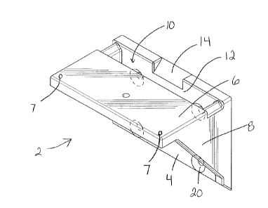
Figure 1 is a front perspective view of the deck support
bracket looking downwardly on the bracket;
Figure 2 is a front perspective view of the deck support
bracket looking upwardly at a top of the member of the
bracket;
Figure 3 is a partial perspective view showing two deck
support brackets secured to a joist about to secure and
support an end of a deck board to one side of the joist;
Figure 4 is a perspective view of the two deck support
brackets secured for supporting an end of a further deck
board (not shown);
Figure 5 is a side view through a decking structure where
the deck support bracket is attached to a joist and one
deck board partially overhangs the joist and a second deck
board has an end thereof spaced outwardly from the joist
and supported by the bracket;
Figure 6 is an end view showing the deck support bracket
used to secure two adjacent deck boards using a specialized
central fastening arrangement;
Figure 7 is a view similar to Figure 5 showing the bracket
being used with screws for securing deck boards from below
the deck surface;
Figure 8 is a view showing deck boards being secured by
passing screws through the top of the deck boards and into
the deck board support bracket;
- 3 -
'
CA 02946102 2016-10-21
P15403CA00
Figure 9 is a view showing screws being used in combination
with slotted deck boards for securing of the deck boards
to the deck support bracket;
Figure 10 is a perspective view of a modified deck board
support bracket which is of an increased size for different
applications bridging underneath a board for attachment on
opposite sides of the board; and
Figure 11 is a sectional view illustrating the modified
deck support bracket of Figure 10 used to support three
deck boards.
DETAILED DESCRIPTION OF THE PREFERRED EMBODIMENTS
The deck support bracket 2 shown in Figures 1 and 2 includes
a back member 4 used to secure the deck support bracket 2
to a joist or other structure. A top mount member 6 is
positioned to one side of and perpendicular to the back
member 4 with a flow-through drainage arrangement 10
separating the back member 4 from the top mount member 6.
The drainage arrangement 10 is preferably an open slot. At
least two gusset supports 8 are provided that join the top
mount member 6 to the back member 4. Depending upon the
length of the deck support bracket 2, additional gusset
supports can be provided. For many applications, only two
gusset supports 8 will be provided. These gusset supports
8 are preferably provided adjacent the ends of the deck
support bracket 2. The corner holes 7 are positioned to
locate fasteners that pass through the holes and engage a
deck board preferably at least one inch from a side of the
deck board and at least one inch from the end of a deck
board for securement from below the deck board.
- 4 -
CA 02946102 2016-10-21
P15403CA00
The deck support bracket 2 is particularly useful when used
with wooden deck boards and joists and other structures
however it is also useful with all composite and PVC deck
boards and/or joists and other structures and any
combinations thereof. The type of material support by the
bracket does appreciably impact the utility.
The back member 4 includes a series of screw ports 20 used
to attach the back member to the face of a joist. In the
particular embodiment shown, four such screw ports 20 are
provided however the positioning, placement and the number
of screw ports can vary.
The deck support bracket 2 is preferably used such that the
angle drainage face 14 is positioned in a gap between
parallel deck boards. As is shown in Figure 5, the present
deck support bracket 2 is advantageously used to allow
moisture to pass through the deck and in particular allow
moisture to pass between two deck boards which are
positioned end to end but have a gap therebetween (spaced
butt joint).
The deck support bracket 2 as shown in Figure 2 includes a
securing boss 18 generally on a center line with respect
to the width of the bracket and this securing boss can be
used with respect to the particular fastening arrangement
for securing adjacent parallel deck boards.
The deck support bracket 2 is preferably of a unitary
construction and preferably is injection molded using a
suitable plastic material.
The particular plastic or
reinforced plastic material can be appropriately selected
in accordance with the required design load
characteristics.
The at least two gusset supports 8 form a strong mechanical
connection between the top mount member 6 and the back
- 5 -
CA 02946102 2016-10-21
P15403CA00
member 4. These gusset supports resist deflection of the
top mount member 4 and effectively form braces between a
joist and the end of a deck board which is positioned to
one side of the joist.
As shown in Figures 3 and 4, two deck support brackets 2a
and 2b are used to support the butt end of deck board 42a
about to be secured. The end of deck board 42a will not
overlie the joist 40 as it is spaced to one side of the
joist.
The two deck board support brackets 2a and 2b
provide the structural connection between the joist 40 and
the end of the deck board 42a. Furthermore the deck board
42b is positioned to have its butt end 45 at least
overlapping with the joist 40 and in the preferred
embodiment as shown partially overhangs the joist 40.
Figure 4 shows a preferred arrangement where the adjacent
deck board 42 passes over the joist and over part of the
deck support bracket 2a. AS shown in Figure 4 any moisture
that comes into contact with the deck at a position of the
two abutting deck boards 42a and 42b would freely pass
through the drainage gap provided by each of the deck board
support brackets. In addition, it can be appreciated that
there is a portion of the deck board 42a that is
intermediate the two deck support brackets 2a and 2b and
water can pass between the opposed spaced ends of the deck
boards 42a and 42b.
With this arrangement, the opposed ends of each of the deck
boards 42a and 42b are less prone to deterioration caused
by exposure to moisture over an extended period of time.
Furthermore the underlying joist 40, and particularly the
top surface thereof, is less prone to damage due to
accumulated moisture as the deck boards do not abut at the
joist and deck boards 42a and 42b do not abut over what
would be the center line of the joist 40.
- 6 -
CA 02946102 2016-10-21
P15403CA00
The sectional view of Figure 5 shows the deck board 42a
supported by the deck support bracket 2 such that the end
43 of the deck board 42a is located over the flow through
drainage arrangement 10. The deck board 42b and its end
45 pass over the joist 40 and the end 45 is preferably
generally aligned with the back member 4.
With this
arrangement deck board 42b, as it passes over the joist 40,
protects the joist and the end 45 of the deck board 42b is
less prone to damage as moisture is encouraged to pass
between the two ends 43 and 45 rather than accumulate
between such ends.
As shown in Figure 5 the possible securement length for
deck boards 42a and 42b has dramatically increased due to
the top surface of the deck support bracket 2. Deck board
42b overhangs joist 40 and any fastener such as a screw can
pass through the deck board at least 0.75 to 1.0 inches
from the end of the board. This is within the recommended
distance to avoid splitting or cracking. Essentially deck
board 42b has the entire width of the joist plus a small
overhang that can be used for securement (see Figure 4).
Deck board 42a can also be secured with sufficient spacing
from the end thereof due to the width of the top mount
member 6.
For wood deck boards the recommended spacing from the end
of a deck board is one inch.
With a joist width of 1.5
inches and a partial overhang this can be realized for both
deck boards 42a and 42b.
The deck support bracket 2 accommodates different
securement with appropriate spacing from the ends of the
deck boards.
As shown in Figure 3 and 4, the preferred arrangement for
supporting of the deck boards 42a and 42b using this type
- V -
CA 02946102 2016-10-21
=
P15403CA00
of connection, uses two deck support brackets 2 with each
of these brackets essentially centered in the gap between
parallel deck boards and supporting an end of a deck board
spaced to one side of the joist.
Figures 6 through 9 show different fastening arrangements
for securing of deck boards to the top mount member of the
deck support bracket.
Figures 6 and 7 show the deck support bracket 2 in
combination with a hidden fastener type arrangement for
securing of deck boards. The injection molded deck support
bracket 2 allows engagement with a diverse group of
fasteners and different orientations in contrast to
specialized dedicated systems.
In Figure 6 the deck boards 42 on the sides thereof include
an elongate securing slot 44 for use with the specialized
securing member 80. Member 80 includes a plate member 82
that engages each of these slots of the deck boards 42 and
a screw fastener 84 is positioned to pass through the top
mount member 4 and into the underlying securing boss 18.
The fastening arrangement 80 would also be used with
respect to securing of deck boards to joists where each of
the deck boards pass over a joist.
With respect to the
securing arrangement of Figure 3, the deck board 42b would
have one of these fasteners securing of the deck board to
the joist 40 and the deck board 42a would have this type
of fastener securing the end of 42a to the top member of
the support bracket.
Where deck boards 42a and 42b are
supported as shown in Figure 3, deck board 42a will be
secured to the top member 6 and the deck board 42b will be
directly secured to the joist 40.
There are also other securing arrangements, such as shown
in Figure 7, where fasteners are provided below the deck
surface and extend from below the deck surface upwardly to
- 8 -
CA 02946102 2016-10-21
=
1"15403CA00
secure the deck boards.
Different types of fastening
arrangements are used to perform under deck fastening
however the deck support bracket 2 can have fasteners 90
pass through the top member 6 and appropriately engage the
deck boards.
Figure 8 illustrates a more conventional use of the deck
support bracket 2 and fasteners 100 that pass through the
deck boards and engage the top member 6. If the end of the
deck board 42a is positioned to one side of the joist 40
then fastener 100a would pass through the top member 6. In
contrast, if deck board 42b passes completely over both the
joist 40 and the deck support bracket 2, the screw 100b
would preferably engage the joist 40. In the embodiment
shown, deck board 42b is attached to the top member 6 and
a further screw, not shown, would pass through the deck
board 42b and engage the joist 40. The additional screw
100b can provide some additional assistance in maintaining
the position of the top mount member 6 as it is attached
to the continuous deck board 42b.
Figure 9 shows yet a further fastening arrangement where
the screws 110 are driven from above at an angle and pass
through the slots 120 and engage the top mount member 6.
This type of angled screw securement still provides a
hidden-type fastening of the deck boards 42 to the
underlying support structure. The deck boards 42a and 42b
are shown as having slots 120 however these deck boards
could be conventional wood deck boards with the screws
passing at an angle through the sides thereof. Normally
when deck boards are side by side as shown in Figure 9, one
of the deck boards will continue over the joist and deck
support bracket 2 and the end of the board will be at a
different location (see Figure 4). Securing both side by
side boards to the top mount member 6 improves structural
integrity.
- 9 -
CA 02946102 2016-10-21
P15403CA00
The deck support bracket 2 as shown In Figure 1 and 2, as
well as the deck support bracket 202 (Figure 10), is
specifically designed to provide a desirable spaced
abutting-type connection of two deck boards to one side of
an underlying joist. The deck support bracket 202 is of
increased length and can be used with larger size deck
boards and/or used with smaller deck boards such that one
bracket can be used to underlie one full board and partially
underlie the two adjacent deck boards. The deck support
bracket 202 includes the back member 204, the top mount
member 206 and the support gussets 283.
The central board 250 extends over the joist but stops on
the bracket. Deck boards 251 and 252 are through boards.
With extended bracket 202 two bosses 260 and 261 are
positioned in the gaps between boards for receiving the
fastener 270 for engaging board slots as previously
described. A sloped drainage edge 280 runs generally to
the width of the bracket 202. Four gussets 283 are shown
but additional gussets may be provided. This bracket is
capable of receiving top down screws, bottom up screws and
diagonal screws. The bracket is typically about 7.5 inches
wide when used for 5 a inch boards. Six ports 273 can be
used for bottom up screws. The bracket 202 adjacent the
back member 204 includes a drainage slot 281. The end walls
of the drainage slot 281 include an angled top surface 285
to promote drainage. The drainage slot 281 is positioned
between end to end deck boards and any moisture is
encouraged to pass through the slot protecting any deck
boards adjacent the slot.
A number of different fastening arrangements have been
described and these fastening arrangements can be used in
combination.
It can also be appreciated that these deck support brackets
2 and 202 can advantageously be used in other applications
- 10 -
CA 02946102 2016-10-21
Pl5403CA00
where it is desirable to secure deck boards to underlying
joists. For example, many deck configurations now use deck
boards at different angles or deck boards used to define a
very unique pattern and these brackets can also be used as
conventional type support brackets.
In the preferred embodiment the ends of the deck boards are
shown with an appreciable gap between abutting ends. This
is normally preferred, however in some applications a
smaller gap can be used while still providing the desirable
drainage between abutting deck boards.
Therefore
significant variations are available to the end user to
accommodate particular requirements or configurations.
The deck board support brackets are preferably made of a
suitable plastic or injection molding material, however, a
bracket made of steel or metal is also a practical
alternative. Typically, such a metal bracket would be
formed as part of a progressive stamping/bending process.
Therefore, the present invention is not limited to an
injection molded product and a deck board bracket of a
metal or other material having the claimed features is also
included.
Although preferred embodiments of the invention have been
described here in detail, it will be understood by those
skilled in the art that variations may be made thereto,
without departing from the invention, as described and
claimed in the present application.
- 11 -