Note: Descriptions are shown in the official language in which they were submitted.
CA 02946601 2016-10-21
WO 2016/141181 PCT/US2016/020680
DRILL BITS HAVING FLUSHING
. . _
10001]
FIELD
10002] This invention relates to drill bits for cutting a hole in a
formation, and, more
particularly, to drill bits having circumferentially spaced crown portions for
cutting a hole in
a formation.
BACKGROUND
[0003] Existing drill bits typically have a central waterway and a series
of channels that
provide fluid communication between a side surface of the bit and the central
waterway (with
no channels positioned directly on the cutting surface of the bit). The
central waterway is
needed to permit removal of cuttings over the entire face of the drill bit.
These existing drill
bits do not permit direct flow of water on the cutting surface of the bits.
The lack of water on
the cutting surface results in a decrease in the rate at which cuttings are
removed, thereby
leading to an increase in the wear of the cutting surface. Additionally, the
lack of water flow
can also minimize the removal of heat from the cutting surface during high-
rotational
operation of the bit. These known drill bit designs are also associated with
relatively low
penetration rates and reduced contact stress measurements.
[0004] Thus, there is a need in the pertinent art for drill bits that more
effectively provide
high velocity fluid flow to the cutting surface of the bit and remove heat
from the cutting
surface. There is a further need in the pertinent art for drill bits that
provide increased cutting
removal rates and penetration rates in comparison to conventional drill bits.
SUMMARY
[0005] Disclosed herein, in one aspect, is a drill bit for cutting a hole
in a formation.
The drill bit has a longitudinal axis bisecting a center of the drill bit and
includes a shank and
a crown having an operative circumference. The crown has a base surface and a
plurality of
crown portions spaced apart relative to the operative circumference of the
crown The
CA 02946601 2016-10-21
WO 2016/141181
PCT/US2016/020680
plurality of crown portions can include two, three, four, or more crown
portions. Each crown
portion of the plurality of crown portions has a first longitudinal edge, a
second longitudinal
edge, an outer surface that extends between the first longitudinal edge and
the second
longitudinal edge and defines a portion of the operative circumference of the
crown, at least
one inner surface, and a cutting face. The at least one inner surface extends
from the first
longitudinal edge to the second longitudinal edge. The base surface is spaced
from the
cutting faces of the plurality of crown portions relative to the longitudinal
axis of the drill bit.
The base surface cooperates with the inner surfaces of the plurality of crown
portions to
define a slot. The crown and the shank cooperate to define an interior space
about the
longitudinal axis. The interior space can be configured to receive water or
other drilling fluid
during use of the drill bit.
[0006] Optionally, the crown has a first crown portion and a second crown
portion that
are spaced apart relative to a first transverse axis that is perpendicular to
the longitudinal axis.
Each of the first and second crown portions has a first longitudinal edge, a
second
longitudinal edge, an outer surface, at least one inner surface, and a cutting
face. The outer
surface extends between the first longitudinal edge and the second
longitudinal edge and
defines a portion of the operative circumference of the crown. In one optional
aspect, the at
least one inner surface of each of the first and second crown portions has a
first inner surface,
a second inner surface, and a longitudinal medial edge. The first inner
surface extends from
the first longitudinal edge of the crown portion to the longitudinal medial
edge of the crown
portion. The second inner surface extends from the second longitudinal edge of
the crown
portion to the longitudinal medial edge.
[0007] In a further aspect, the first inner surfaces of the first and
second crown portions
have respective lengths corresponding to the distance between the first
longitudinal edge and
the longitudinal medial edge of the crown portion. The second inner surfaces
of the first and
second crown portions have respective lengths corresponding to the distance
between the
second longitudinal edge and the longitudinal medial edge of the crown
portion. Optionally,
the length of the first inner surface of the first crown portion does not
equal the length of the
second inner surface of the first crown portion. Optionally, the length of the
first inner
surface of the second crown portion does not equal the length of the second
inner surface of
the second crown portion.
[0008] In another aspect, the cutting faces of the first and second crown
portions have
respective heights relative to the longitudinal axis of the drill bit. The
height of the first
2
CA 02946601 2016-10-21
WO 2016/141181
PCT/US2016/020680
crown portion can be substantially equal to the height of the cutting face of
the second crown
portion.
[0009] In another aspect, the base surface and the cutting face of the
first crown portion
are spaced apart a first axial distance relative to the longitudinal axis. The
first axial distance
can vary moving across the base surface relative to the first traverse axis.
In a further aspect,
the first axial distance can vary moving across the base surface relative to a
second traverse
axis that is perpendicular to the longitudinal axis and the first traverse
axis.
[0010] In one aspect, the base surface can have a compound curvature. In a
further
aspect, the base surface can have an apex. The apex can be spaced from the
center of the drill
bit relative to the longitudinal axis. Optionally, the apex can be positioned
proximate the at
least one inner surface of the first crown portion. Optionally, the apex can
be positioned
proximate the at least one inner surface of the second crown portion.
[0011] In another aspect, the base surface can extend from a first base
edge to a second
base edge relative to a second transverse axis that is perpendicular to the
longitudinal axis
and the first transverse axis. The first base edge can extend between the
first inner surfaces of
the first and second crown portions, and the second base edge can extend
between the second
inner surfaces of the first and second crown portions.
[0012] Optionally, within a plane extending through the apex and extending
parallel to
the longitudinal axis and the second traverse axis, the base surface can
define a first portion
extending between the first base edge and the apex and a second portion
extending between
the second base edge and the apex. In a further aspect, the first portion of
the base surface can
be positioned at a first selected angle relative to the second transverse
axis, and the second
portion of the base surface can be positioned at a second selected angle
relative to the second
transverse axis.
[0013] Additional advantages of the invention will be set forth in part in
the description
which follows, and in part will be obvious from the description, or may be
learned by practice
of the invention. The advantages of the invention will be realized and
attained by means of
the elements and combinations particularly pointed out in the appended claims.
It is to be
understood that both the foregoing general description and the following
detailed description
are exemplary and explanatory only and are not restrictive of the invention,
as claimed.
3
CA 02946601 2016-10-21
WO 2016/141181
PCT/US2016/020680
DETAILED DESCRIPTION OF THE FIGURES
[0014] These and other features of the preferred embodiments of the
invention will
become more apparent in the detailed description in which reference is made to
the appended
drawings wherein:
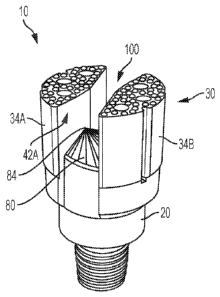
[0015] FIG. 1 is a top perspective view of an exemplary drill bit having
two crown
portions as disclosed herein, taken from a first side of the drill bit.
[0016] FIG. 2 is a top perspective view of the drill bit of FIG. 1, taken
from an opposed
side of the drill bit.
[0017] FIG. 3 is a bottom perspective view of the drill bit of FIG. 1.
[0018] FIG. 4 is a front side view of the drill bit of FIG. 1, showing the
slot defined by
the base surface and the first and second crown portions as disclosed herein.
[0019] FIG. 5 is a back side view of the drill bit of FIG. 1.
[0020] FIG. 6 depicts a left or right side view of the drill bit of FIG. 1.
[0021] FIG. 7 depicts a top view of the drill bit of FIG. 1.
[0022] FIG. 8 depicts a bottom view of the drill bit of FIG. 1.
[0023] FIG. 9 depicts a cross-sectional view of the drill bit of FIG. 1,
taken within plane
130.
[0024] FIG. 10 depicts a cross-sectional view of the drill bit of FIG. 1,
taken within
plane 140.
[0025] FIG. 11 is a top perspective view of another exemplary drill bit
having two crown
portions as disclosed herein.
[0026] FIG. 12 is a right side view of the drill bit of FIG. 11.
[0027] FIG. 13 is a left side view of the drill bit of FIG. 11.
[0028] FIG. 14 is atop view of the drill bit of FIG. 11.
[0029] FIG. 15 is top perspective view of an exemplary drill bit having
three crown
portions as disclosed herein.
[0030] FIG. 16 is a first side view of the drill bit of FIG. 15, showing a
first slot portion
defined by first and second crown portions of the bit.
4
CA 02946601 2016-10-21
WO 2016/141181
PCT/US2016/020680
[0031] FIG. 17 is a second side view of the drill bit of FIG. 15, showing a
second slot
portion defined by second and third crown portions of the bit.
[0032] FIG. 18 is a third side view of the drill bit of FIG. 15, showing a
third slot portion
defined by the first and third crown portions of the bit.
[0033] FIG. 19 is atop view of the drill bit of FIG. 15.
[0034] FIG. 20 depicts an exemplary drilling system comprising a drill bit
as disclosed
herein.
DETAILED DESCRIPTION
[0035] The present invention can be understood more readily by reference to
the
following detailed description, examples, drawings, and claims, and their
previous and
following descriptions. However, before the present devices, systems, and/or
methods are
disclosed and described, it is to be understood that this invention is not
limited to the specific
devices, systems, and/or methods disclosed unless otherwise specified, as such
can, of course,
vary. It is also to be understood that the terminology used herein is for the
purpose of
describing particular aspects only and is not intended to be limiting.
[0036] The following description of the invention is provided as an
enabling teaching of
the invention in its best, currently known embodiment. To this end, those
skilled in the
relevant art will recognize and appreciate that many changes can be made to
the various
aspects of the invention described herein, while still obtaining the
beneficial results of the
present invention. It will also be apparent that some of the desired benefits
of the present
invention can be obtained by selecting some of the features of the present
invention without
utilizing other features. Accordingly, those who work in the art will
recognize that many
modifications and adaptations to the present invention are possible and can
even be desirable
in certain circumstances and are a part of the present invention. Thus, the
following
description is provided as illustrative of the principles of the present
invention and not in
limitation thereof
[0037] As used throughout, the singular forms "a," "an" and "the" include
plural
referents unless the context clearly dictates otherwise. Thus, for example,
reference to "a
bore" can include two or more such bores unless the context indicates
otherwise.
[0038] Ranges can be expressed herein as from "about" one particular value,
and/or to
"about" another particular value. When such a range is expressed, another
aspect includes
from the one particular value and/or to the other particular value. Similarly,
when values are
CA 02946601 2016-10-21
WO 2016/141181
PCT/US2016/020680
expressed as approximations, by use of the antecedent "about," it will be
understood that the
particular value forms another aspect. It will be further understood that the
endpoints of each
of the ranges are significant both in relation to the other endpoint, and
independently of the
other endpoint.
[0039] As used herein, the terms "optional" or "optionally" mean that the
subsequently
described event or circumstance may or may not occur, and that the description
includes
instances where said event or circumstance occurs and instances where it does
not.
[0040] The word "or" as used herein means any one member of a particular
list and also
includes any combination of members of that list.
[0041] Described herein with reference to FIGS. 1-20 is a drill bit 10, 200
for cutting a
hole in a formation, such as, for example and without limitation, hard rock.
Optionally, the
formation of the hole can be used in mineral exploration applications. The
drill bit 10, 200
has a longitudinal axis 12, 202. In exemplary aspects, the drill bit 10, 200
can comprise a
shank 20, 220 and a crown 30, 230. In this aspect, the crown 30, 230 has an
operative
circumference 32, 232. It is contemplated that the drill bits disclosed herein
can provide an
improved penetration rate relative to conventional drill bits. It is further
contemplated that
the drill bits disclosed herein can provide enhanced chip/cutting removal and
enhanced
cooling (and heat removal) of the cutting face of the bit, as measured
relative to conventional
drill bits. More particularly, it is contemplated that the drill bits
disclosed herein can more
effectively provide high velocity fluid flow to the cutting surface of the
bit. It is still further
contemplated that the drill bits disclosed herein can provide improved wear
resistance relative
to conventional drill bits. In exemplary aspects, the drill bit 10, 200 can be
a full face drill
bit, such as, for example, a full face core drill bit. It is contemplated that
the full face drill
bits disclosed herein can be used in conditions when a core sample is not
required.
[0042] In use, the drill bit 10, 200 can be configured to channel and
fracture a micro-core
from the center of the drill bit and direct and/or flush the fractured micro-
core to the outer
diameter of the drill bit. Complementarily, this exemplary configuration
allows for reduced
wear of the inner diameter of the drill bit, which is the typical wear mode of
conventional full
face bits. Further, the exemplary full face drill bit can increase the rate of
penetration in
comparison to conventional full face bits that, due to their intrinsic design
limitations, have a
limited ability to cut at the center of the full face bit as a result of the
very low surface
velocities.
6
CA 02946601 2016-10-21
WO 2016/141181
PCT/US2016/020680
[0043] On skilled in the art will appreciate that conventional full face
bits typically wear
from the center of the upper contact face of the drill bit as a result of low
cutting velocity and
poor chip flushing. This design failure mode is exacerbated as the rock being
drilled
increases in hardness. The cycle of wear in the center of a full face bit
leads to further
reduced flushing in the center, which in-turn causes more wear, drastically
limiting the
potential life of full face bits when compared to coring bits. In the past,
bit designs have
attempted to overcome this design failure mode by adding one or more of a
center port and/or
waterways that are distributed on the bit or by reinforcing the center port
waterway to reduce
the wear rate at the center of the bit.
[0044] In exemplary aspects, the disclosed drill bits 10, 200 can comprise
a plurality of
crown portions spaced apart relative to the operative circumference 32, 232 of
the crown 30,
230. In these aspects, and as further disclosed herein, it is contemplated
that each crown
portion of the plurality of crown portions can have a first longitudinal edge,
a second
longitudinal edge, an outer surface, at least one inner surface, and a cutting
face. The outer
surface extends between the first longitudinal edge and the second
longitudinal edge and
defines a portion of the operative circumference of the crown. In combination,
the at least
one inner surface extends from the first longitudinal edge to the second
longitudinal edge. In
further aspects, the drill bit 10, 200 can comprise a base surface 80, 280
spaced from the
cutting faces of the plurality of crown portions relative to the longitudinal
axis 12, 202 of the
drill bit. As further disclosed herein, the base surface 80, 280 of the drill
bit 10, 200 can
cooperate with the inner surfaces of the plurality of crown portions to define
a slot 100, 300.
As further disclosed herein, each crown portion of the bit 10, 200 is spaced
from other crown
portions by respective slot portions. As further disclosed herein, the crown
30, 230 and the
shank 20, 220 can cooperate to define an interior space about the longitudinal
axis 12, 202.
[0045] As further disclosed herein, the base surface 80, 280 of the drill
bit can have an
apex 84, 284 that is spaced from a center point 18, 210 of the drill bit and
positioned within a
portion of the slot 100, 300 that is outwardly tapered as it moves toward the
outer diameter of
the drill bit. In operation, it is contemplated that the inner surfaces of
each crown portion can
define a leading portion and a trailing portion, with at least the trailing
portion being
outwardly tapered moving away from the center 18, 210 of the drill bit and
toward the outer
diameter of the drill bit. It is further contemplated that the outward
tapering of the trailing
portions of the crown portions can create additional relief in the dispersal
of cuttings during
rotation of the drill bit.
7
CA 02946601 2016-10-21
WO 2016/141181
PCT/US2016/020680
[0046] Optionally, the plurality of crown portions can comprise at least
two crown
portions. In exemplary aspects, the plurality of crown portions can optionally
comprise at
least three crown portions. In further exemplary aspects, the plurality of
crown portions can
optionally comprise at least four crown portions. However, it is contemplated
that the
plurality of crown portions can comprise any selected number of crown
portions.
Drill Bits Having Two Crown Portions
[0047] In exemplary aspects, and with reference to FIGS. 1-14, the drill
bits disclosed
herein can have a first crown portion 34A and a second crown portion 34B. In
these aspects,
it is contemplated that the drill bits disclosed herein can be plug and/or non-
coring bits. In
still further exemplary aspects, it is contemplated that the drill bits
disclosed herein can be
concave-faced drill bits. In still further exemplary aspects, it is
contemplated that the drill
bits disclosed herein can be non-concave faced drill bits.
[0048] In one aspect, the first crown portion 34A and the second crown
portion 34B can
be spaced apart relative to a first transverse axis 14 that is perpendicular
to the longitudinal
axis 12. In a further aspect, each of the first and second crown portions 34A,
34B can
comprise a first longitudinal edge 36A, 36B, a second longitudinal edge 38A,
38B, an outer
surface 40A, 40B, at least one inner surface 42A, 42B, and a cutting face 60A,
60B. In this
aspect, the outer surface 40A, 40B can extend between the first longitudinal
edge 36A, 36B
and the second longitudinal edge 38A, 38B. As shown in FIGS. 7-8, the outer
surface 40A,
40B can define a portion of the operative circumference 32 of the crown 30. In
another
aspect, the at least one inner surface 42A, 42B of each of the first and
second crown portions
34A, 34B can extend from the first longitudinal edge 36A, 36B to the second
longitudinal
edge 48A, 48B of the crown portion. Optionally, in exemplary aspects, the
radial distance
from the center 18 of the bit to the outer surfaces 40A, 40B of the crown
portions 34A, 34B
can range from about 0.625 inches to about 6.25 inches.
[0049] Optionally, in exemplary aspects, the at least one inner surface
42A, 42B of the
first and second crown portions 34A, 34B can comprise a plurality of inner
surfaces. In one
aspect, each of the first and second crown portions 34A, 34B can respectively
have a first
inner surface 44A, 44B, a second inner surface 48A, 48B, and a longitudinal
medial edge
74A, 74B. In one aspect, the first inner surface 44A, 44B can extend from the
first
longitudinal edge 36A, 36B of the crown portion 34A, 34B to the longitudinal
medial edge
74A, 74B of the crown portion 34A, 34B. In this aspect, the second inner
surface 48A, 48B
8
CA 02946601 2016-10-21
WO 2016/141181
PCT/US2016/020680
can extend from the second longitudinal edge 38A, 38B of the crown portion to
the
longitudinal medial edge 74A, 74B. Optionally, in exemplary aspects, the
longitudinal medial
edges 74A, 74B of the first and second crown portions 34A, 34B can be
positioned on
opposed sides of the first transverse axis 14, which passes through the center
18 of the drill
bit.
[0050] In additional optional aspects, the second inner surface 48A, 48B of
each of the
first and second crown portions 34A, 34B is substantially flat. Alternatively,
in other
optional aspects, and with reference to FIGS. 11-14, at least a portion of the
second inner
surface 48A, 48B of the first and second crown portions 34A, 34B can be
curved. In these
aspects, it is contemplated that the second inner surface 48A, 48B of at least
one of or both of
the first and second crown portions 34A, 34B can be angled or tapered away
from a second
transverse axis 16 that is perpendicular to the longitudinal axis 12 and the
first transverse axis
14, moving from the longitudinal medial edge 74A, 74B to the second edge 38A,
38B of the
crown portion. It is further contemplated that the curve can have any desired
curvature
profile, such as, for example and without limitation, a convex curve, a
concave curve, a
serpentine pattern, and the like. Optionally, in exemplary aspects, it is
further contemplated
that the second inner surface 48A, 48B of each of the first and second crown
portions 34A,
34B can have a first portion 49A, 49B proximate the longitudinal medial edge
74A, 74B. In
these aspects, the second inner surface 48A, 48B of each of the first and
second crown
portions 34A, 34B can have a second portion 51A, 51B extending from the first
portion 49A,
49B to the second edge 38A, 38B of the crown portion. In exemplary aspects,
the first
portion 49A, 49B can have a greater radius of curvature than the second
portion 51A, 51B.
Optionally, however, it is contemplated that the first and second portions can
have
substantially equal radii of curvature. Optionally, it is further contemplated
that the second
portion MA, 51B can have a greater radius of curvature than the first portion
49A, 49B.
[0051] In further exemplary aspects, the first edges 36A, 36B of the first
and second
crown portions 34A, 34B can be spaced apart by a first distance relative to
the first transverse
axis 14, and the second edges 38A, 38B of the first and second crown portions
34A, 34B can
be spaced apart by a second distance relative to the first transverse axis 14.
Optionally, in
exemplary aspects, the first and second distances can range from about 0.125
inches to about
1 inch. Optionally, in these aspects, the second distance can be greater than
the first distance.
In additional optional aspects, it is contemplated that at least a portion of
the first inner
surface 44A, 44B of each of the first and second crown portions 34A, 34B can
be
9
CA 02946601 2016-10-21
WO 2016/141181
PCT/US2016/020680
substantially flat. In these aspects, the first inner surface 44A, 44B of each
of the first and
second crown portions 34A, 34B can be angled away from the second transverse
axis 16.
Optionally, in further exemplary aspects, it is contemplated that at least a
portion of the first
inner surface 44A, 44B of each of the first and second crown portions 34A, 34B
can be
curved. In these aspects, it is contemplated that the curve can have any
desired curvature
profile, such as, for example and without limitation, a convex curve, a
concave curve, a
serpentine pattern, and the like.
[0052] As one will appreciate, and with reference to FIGS. 7 and 14, during
normal
rotation of the drill bit 10, the first inner surface 44A of the first crown
portion 34A and the
second inner surface 48B of the second crown portion 34B can serve as the
leading edges of
the drill bit, with the second inner surface 48A of the first crown portion
and the first inner
surface 44B of the second crown portion serving as the trailing edges of the
drill bit.
However, it is contemplated that the direction of rotation of the drill bit
can be reversed, such
that the second inner surface 48A of the first crown portion 34A and the first
inner surface
44B of the second crown portion 34B serve as the leading edges of the drill
bit, with the first
inner surface 44A of the first crown portion and the second inner surface 48B
of the second
crown portion serving as the trailing edges of the drill bit.
[0053] In exemplary aspects, the first inner surface 44A and the second
inner surface
48A of the first crown portion 34A can be angularly oriented relative to each
other at a first
desired angle 52. In these aspects, the first inner surface 44B and the second
inner surface
48B of the second crown portion 34B can be angularly oriented relative to each
other at a
second desired angle 54. It is contemplated that the first desired angle 52
can be substantially
equal to the second desired angle 54. Alternatively, it is contemplated that
the first desired
angle 52 can be different than the second desired angle 54. The first desired
angle 52 can
range from about 30 to about 330 , preferably range from about 135 to about
225 , and
more preferably be about 200 . The second desired angle 54 can range from
about 30 to
about 330 , preferably range from about 135 to about 225 , and more
preferably be about
200 .
[0054] In one aspect, the first inner surfaces 44A, 44B of the first and
second crown
portions 34A, 34B have respective lengths that correspond to the distance
between the first
longitudinal edge 36A, 36B and the longitudinal medial edge 74A, 74B of each
crown
portion. Optionally, in exemplary aspects, the length of the first inner
surface 44A of the first
crown portion 34A does not equal the length of the first inner surface 44B of
the second
CA 02946601 2016-10-21
WO 2016/141181
PCT/US2016/020680
crown portion 34B. However, it is contemplated that the lengths of the first
inner surfaces
44A, 44B can optionally be substantially equal. In other aspects, the second
inner surfaces
48A, 48B of the first and second crown portions 34A, 34B have respective
lengths that
correspond to the distance between the second longitudinal edge 38A, 38B and
the
longitudinal medial edge 74A, 74B of the crown portion 34A, 34B. Optionally,
in exemplary
aspects, the length of the second inner surface 48A of the first crown portion
34A does not
equal the length of the second inner surface 48B of the second crown portion
34B. However,
it is contemplated that the lengths of the second inner surfaces 48A, 48B can
optionally be
substantially equal.
[0055] In one exemplary aspect, the length of the first inner surface 44A
of the first
crown portion 34A does not equal the length of the second inner surface 48A of
the first
crown portion 34A. In another exemplary aspect, the length of the first inner
surface 44B of
the second crown portion 34B does not equal the length of the second inner
surface 48B of
the second crown portion 34B. Optionally, in a further exemplary aspect, the
length of the
first inner surface 44A of the first crown portion 34A does not equal the
length of the second
inner surface 48A of the first crown portion 34A, and the length of the first
inner surface 44B
of the second crown portion 34B does not equal the length of the second inner
surface 48B of
the second crown portion 34B.
[0056] In one aspect, the cutting faces 60A, 60B of the first and second
crown portions
34A, 34B have respective heights relative to the longitudinal axis 12 of the
drill bit 10.
Optionally, in some exemplary aspects, the height of the cutting face 60A of
the first crown
portion 34A can be substantially equal to the height of the cutting face 60B
of the second
crown portion 34B. However, it is contemplated that the heights of the cutting
faces 60A,
60B can optionally be different from one another. As shown in FIGS. 3 and 8,
it is
contemplated that the crown portions 34A, 34B and the shank 20 can cooperate
to define an
interior space 110 about the longitudinal axis 12. It is further contemplated
that the interior
space 110 can be configured to receive water or other drilling fluid during
use of the drill bit
10. In one aspect, the water or other drilling fluid can be supplied to the
interior space 110 at
a desired pressure using conventional means.
[0057] In another aspect, each of the first and second crown portions 34A,
34B can
define a plurality of bores 64A, 64B extending from the cutting faces 60A, 60B
to the interior
space 110. In this aspect, it is contemplated that the plurality of bores 64A,
64B can be
configured to direct water (or other drilling fluid) substantially directly to
the cutting faces
11
CA 02946601 2016-10-21
WO 2016/141181
PCT/US2016/020680
60A, 60B from the interior space 110. This direct supply of drilling fluid to
the cutting faces
60A, 60B is distinguishable from the supply of fluid by ports within junk
slots that are
recessed relative to a cutting face. It is further contemplated that the
direct supply of
pressurized water (or other drilling fluid) to the cutting faces 60A, 60B can
increase flow
velocity across the cutting faces, thereby permitting more rapid removal of
cuttings and
significantly increasing the convective cooling of the cutting face. It is
further contemplated
that the plurality of bores 64A, 64B can reduce the combined contact area of
the cutting faces
60A, 60B relative to the total area of cutting faces of conventional drill
bits, thereby
improving the penetration rate of the drill bit 10. It is still further
contemplated that the
plurality of bores 64A, 64B can permit novel distribution of water (or other
drilling fluid)
relative to the cutting faces 60A, 60B, thereby improving the wear resistance
of the drill bit
10. It is still further contemplated that the plurality of bores 64A, 64B can
provide flexibility
in the distribution of water (or other drilling fluid) such that the center
port of conventional
drill bits is unnecessary (and can be eliminated from the drill bit).
Optionally, in some
aspects, it is contemplated that the cutting faces 60A, 60B can have a convex
profile. In other
aspects, it is contemplated that the cutting faces 60A, 60B can optionally
have a concave
profile.
[0058] In exemplary aspects, the plurality of bores 64A, 64B can optionally
be
substantially equally distributed about the cutting faces 60A, 60B.
Optionally, in some
aspects, the plurality of bores 64A, 64B can be randomly spaced about each of
the first and
second crown portions 34A, 34B. In other aspects, the plurality of bores 64A,
64B can
optionally be substantially uniformly spaced about the cutting faces 60A, 60B.
In these
aspects, it is contemplated that at least two concentric rows of bores can be
provided, with the
bores in each respective row being substantially uniformly spaced about the
cutting faces
60A, 60B.
[0059] More generally, it is contemplated that the plurality of bores 64A,
64B can be
provided in any selected configuration. It is further contemplated that the
plurality of bores
64A, 64B can be distributed so as to optimize the wear characteristics of the
drill bit 10 for a
particular application.
[0060] It is contemplated that each bore of the plurality of bores 64A, 64B
can be
provided in a selected shape. In exemplary aspects, the plurality of bores
64A, 64B can have
a substantially cylindrical shape (with substantially circular cross-sectional
profile).
However, it is contemplated that the plurality of bores 64A, 64B can have any
shape,
12
CA 02946601 2016-10-21
WO 2016/141181
PCT/US2016/020680
including, for example and without limitation, a substantially conical
(tapered) shape (with a
substantially circular cross-sectional profile), a shape having a
substantially rectangular
cross-sectional profile, a shape having a substantially square cross-sectional
profile, an S-
shape, and the like.
[0061] In one aspect, the crown 30 does not completely circumferentially
enclose the
interior space 110. Alternatively, in another aspect, the crown 30 completely
circumferentially encloses the interior space 110. In some exemplary aspects,
the crown
portions 34A, 34B do not comprise a waterway extending radially between the
outer surface
40A, 40B of the first and second crown portions 34A, 34B and the interior
space 110.
[0062] In another aspect, each of the first and second crown portions 34A,
34B can
define a plurality of projections 66A, 66B extending outwardly from the
cutting faces 60A,
60B relative to the longitudinal axis 12 of the drill bit 10. Optionally, the
projections can be
formed integrally with the crown portions 34A, 34B using conventional methods.
Optionally, the projections can comprise the same material as the adjoining
crown portions.
[0063] In exemplary aspects, the plurality of projections 66A, 66B can
optionally be
substantially equally distributed about the cutting faces 60A, 60B.
Optionally, in some
aspects, the plurality of projections 66A, 66B can be randomly spaced about
each of the first
and second crown portions 34A, 34B. In other aspects, the plurality of
projections 66A, 66B
can optionally be substantially uniformly spaced about the cutting faces 60A,
60B. In these
aspects, it is contemplated that at least two concentric rows of projections
can be provided,
with the projections in each respective row being substantially uniformly
spaced about the
cutting faces 60A, 60B.
[0064] More generally, it is contemplated that the plurality of projections
66A, 66B can
be provided in any selected configuration. It is further contemplated that the
plurality of
projections 66A, 66B can be distributed so as to optimize the wear
characteristics of the drill
bit 10 for a particular application.
[0065] It is contemplated that the each projection of the plurality of
projections 66A,
66B can be provided in a selected shape. In exemplary aspects, the plurality
of projections
66A, 66B can have a substantially cylindrical shape (with substantially
circular cross-
sectional profile). However, it is contemplated that the plurality of
projections 66A, 66B can
have any shape, including, for example and without limitation, a substantially
conical
(tapered) shape (with a substantially circular cross-sectional profile), a
shape having a
13
CA 02946601 2016-10-21
WO 2016/141181
PCT/US2016/020680
substantially rectangular cross-sectional profile, a shape having a
substantially square cross-
sectional profile, an S-shape, and the like.
[0066] In a further aspect, the outer surfaces 40A, 40B of the crown
portions 34A, 34B
can define a plurality of channels 68A, 68B extending radially inwardly toward
the
longitudinal axis 12. In exemplary aspects, it is contemplated that the crown
30 can have an
outer diameter that is greater than an outer diameter of the shank 20 such
that the crown
projects radially outwardly relative to the shank. Optionally, in these
aspects, it is further
contemplated that the plurality of channels 68A, 68B can expose and be in
communication
with a junction surface of the shank. It is further contemplated that the
junction surface can
optionally comprise at least one bore positioned in communication with at
least one of the
plurality of channels 68A, 68B of each of the first and second crown portions
34A, 34B. It is
still further contemplated that the at least one bore of the junction surface
of the shank 20 can
be in communication with the interior space 110.
[0067] Optionally, in exemplary aspects, the plurality of channels 68A, 68B
can be
substantially equally circumferentially spaced about the outer surface 40A,
40B of the crown
portions 34A, 34B. In one aspect, it is contemplated that the plurality of
channels 68A, 68B
can optionally be substantially equally sized.
[0068] Optionally, in some exemplary aspects, the plurality of channels 68A
of the first
crown portion 34A can comprise a first plurality of channels and a second
plurality of
channels, with each channel of the first plurality of channels having a first
size and a second
plurality of channels having a second size. In another aspect, the plurality
of channels 68B of
the second crown portion 34B can comprise a first plurality of channels and a
second
plurality of channels, with each channel of the first plurality of channels
having the first size
and a second plurality of channels having the second size. As used herein, the
"size" of a
channel 68A, 68B generally refers to the two-dimensional area of the channel,
as measured
within a plane that is substantially perpendicular to the longitudinal axis of
the drill bit 10. In
these aspects, it is contemplated that the second size can be larger than the
first size. In
additional exemplary aspects, at least one channel of the first plurality of
channels of the first
crown portion 34A can optionally be positioned circumferentially between
sequential
channels of the second plurality of channels of the first crown portion. In
other exemplary
aspects, at least one channel of the first plurality of channels of the second
crown portion 34B
can optionally be positioned circumferentially between sequential channels of
the second
plurality of channels of the second crown portion. In further exemplary
aspects, each channel
14
CA 02946601 2016-10-21
WO 2016/141181
PCT/US2016/020680
of the first plurality of channels of the first and second crown portions 34A,
34B can have a
first radial length, and each channel of the second plurality of channels can
have a second
radial length. In these aspects, it is contemplated that the second radial
length can optionally
be greater than the first radial length.
[0069] In further optional aspects, it is contemplated that the plurality
of channels 68A,
68B can further comprise a third plurality of channels, with each channel of
the third plurality
of channels having a third size that is different than the first and second
sizes (of the first
plurality of channels and the second plurality of channels). It is
contemplated that the third
size can be smaller than the first and second sizes. However, it is
contemplated that, in
exemplary aspects, the third size can also be larger than the first and second
sizes. In
additional exemplary aspects, it is contemplated that at least one channel of
the third plurality
of channels can optionally be positioned circumferentially between a
respective channel of
the first plurality of channels and a respective channel of the second
plurality of channels. In
further exemplary aspects, each channel of the third plurality of channels can
have a third
radial length. In these aspects, it is contemplated that the third radial
length can optionally be
less than the first and second radial lengths (of the first plurality of
channels and the second
plurality of channels). However, in other aspects, it is contemplated that the
third radial
length can optionally be greater than at least one of the first and second
radial lengths.
[0070] More generally, it is contemplated that the plurality of channels
68A, 68B can
comprise channels having any number of different sizes, such as, for example
and without
limitation, channels of at least four different sizes, channels of at least
five different sizes,
channels of at least six different sizes, channels of at least seven different
sizes, and channels
of at least eight different sizes. In exemplary aspects, it is contemplated
that each channel of
the plurality of channels 68A, 68B can have a size that differs from a size of
at least one
additional channel of the plurality of channels.
[0071] In additional aspects, each channel of the plurality of channels 68A
of the first
crown portion 34A can have a width. In a further aspect, each channel of the
plurality of
channels 68B of the second crown portion 34B can have a width. Optionally, in
these aspects,
it is contemplated that each channel of the plurality of channels 68A, 68B can
have a variable
width. For example, the width of each channel 68A of the first crown portion
34A can
decrease from the outer surface 40A of the first crown portion moving radially
inwardly
toward the longitudinal axis 12. The width of each channel 68B of the second
crown portion
34B can decrease from the outer surface 40B of the second crown portion moving
radially
CA 02946601 2016-10-21
WO 2016/141181
PCT/US2016/020680
inwardly toward the longitudinal axis 12. Thus, it is contemplated that each
channel of the
plurality of channels 68A, 68B can be inwardly tapered moving toward the
longitudinal axis
12.
[0072] Optionally, it is contemplated that the radius of the shank 20
(corresponding to
the radial distance between the longitudinal axis 12 and an outer surface of
the shank) can
vary about the circumference of the shank. In exemplary aspects, it is
contemplated that the
outer surface of the shank 20 can be recessed a selected distance from the
outer surfaces 40A,
40B of the crown portions 34A, 34B within each respective channel 68A, 68B. In
these
aspects, it is contemplated that the selected distance by which the outer
surface of the shank
20 is recessed from the outer surfaces 40A, 40B of the crown portions 34A, 34B
can vary
from channel to channel. For example, it is contemplated that the selected
distance by which
the outer surface of the shank 20 is recessed from the outer surfaces 40A, 40B
of the crown
portions 34A, 34B can generally be greater for smaller channels than it is for
larger channels.
However, it is contemplated that any variation in the selected distance (and
the radius of the
shank 20) can be employed. Optionally, in exemplary aspects, the selected
distance by which
the outer surface of the shank 20 is recessed from the outer surfaces 40A, 40B
of the crown
portions can range from about 0.0625 to about 1.5 inches (on each side).
[0073] Optionally, in further exemplary aspects, it is contemplated that an
inner surface
of the shank 20 can define at least one flute extending substantially parallel
to the
longitudinal axis 12 of the bit 10. In these aspects, each flute of the at
least one flute can
optionally correspond to a rounded groove extending radially from the inner
surface of the
shank 20 toward an outer surface of the shank. It is contemplated that the at
least one flute
can optionally be positioned in fluid communication with at least one of a
bore 64A, 64B of
the crown portions 34A, 34B and a bore of the shank 20.
[0074] In one aspect, and as further disclosed herein, the first and second
crown
portions 34A, 34B have a crown outer diameter and the shank has a shank outer
diameter that
is less than the outer diameter of the crown. Further, it is contemplated that
the shank 20 can
further define a tapered surface that extends distally from the shank outer
diameter to the
crown outer diameter. In various aspects, it is contemplated that the tapered
surface can be
angled with respect to the longitudinal axis 12 at an obtuse angle ranging
from about 90.5 to
about 1500, and preferably ranging from about 120 to about 140 .
[0075] In exemplary aspects, the crown 30 of the drill bit 10 disclosed
herein can have a
16
CA 02946601 2016-10-21
WO 2016/141181
PCT/US2016/020680
base surface 80 that is spaced from the cutting faces 60A, 60B of each of the
crown portions
34A, 34B relative to the longitudinal axis 12 of the drill bit. As shown in
FIGS. 1-14, the base
surface 80 and the inner surfaces 42A, 42B of the first and second crown
portions 34A, 34B
can cooperate to define a slot 100 that extends across the drill bit, dividing
the first and
second crown portions.
[0076] In a further aspect, the slot 100 can extend longitudinally therein
a portion of the
cutting faces 60A, 60B and the circumferential outer surface 40A, 40B of the
first and second
crown portions 34A, 34B. It is contemplated that this slot can be configured
to allow for the
fracture and ejection of desired core samples. In an exemplary aspect, a
conduit 120 can be
defined in the drill bit 10 through the base surface 80 and positioned in
communication with
the interior space 110 and a portion of the slot 100. A source of pressurized
drilling fluid can
be positioned in communication with the conduit 120 such that a desired amount
of drilling
fluid can be delivered into the slot during a drilling operation.
[0077] In a further aspect, the base surface 80 and the cutting face 60A of
the first crown
portion 34A can be spaced apart a first axial distance relative to the
longitudinal axis 12.
Optionally, in one exemplary aspect, the first axial distance can vary moving
across the base
surface 80 relative to the first transverse axis 14. In a further exemplary
aspect, the first axial
distance (between the base surface 80 and the cutting face 60A of the first
crown portion 34A
relative to the longitudinal axis 12) can vary moving across the base surface
relative to the
second transverse axis 16. In yet another exemplary aspect, the first axial
distance (between
the base surface 80 and the cutting face 60A of the first crown portion 34A
relative to the
longitudinal axis 12) can vary moving across the base surface relative to both
the first
transverse axis 14 and the second transverse axis 16. Optionally, in exemplary
aspects, the
first axial distance can range from about 0.25 inches to about 8 inches, and,
more preferably,
from about 0.25 inches to about 6 inches.
[0078] In optional contemplated aspects, at least a portion of the base
surface 80 can be
substantially planar and at least a portion of the base surface can be curved
(either distally or
proximally). In other contemplated aspects, the base surface 80 can have a
compound
curvature, with a first portion of the base surface having a first radius of
curvature and at least
a second portion of the base surface having a second radius of curvature
different from the
first radius of curvature.
[0079] In exemplary aspects, it is contemplated that the base surface 80
can further
17
CA 02946601 2016-10-21
WO 2016/141181
PCT/US2016/020680
define an apex 84 that is spaced from the center 18 of the drill bit 10
relative to the
longitudinal axis 12. Optionally, in these aspects, the apex 84 can be spaced
from the center
18 of the drill bit 10 relative to the first transverse axis 14. Optionally,
in another aspect, the
apex 84 can be spaced from the center 18 of the drill bit 10 relative to the
second transverse
axis 16, which is perpendicular to the longitudinal axis 12 and the first
transverse axis 14. In
further aspects, the apex 84 can optionally be positioned proximate an inner
surface 44A,
44B, 48A, 48B of one of the first and second crown portions 34A, 34B.
[0080] In an exemplary aspect, the base surface 80 can extend from a first
base edge 86
to a second base edge 88 relative to the second transverse axis 16. In a
further aspect, the
first base edge 86 can extend between the first inner surfaces 44A, 44B of the
first and second
crown portions 34A, 34B and the second base edge 88 can extend from the second
inner
surfaces 48A, 48B of the first and second crown portions. Optionally, in an
exemplary aspect,
the first base edge 86 can be radially recessed from the outer surfaces 40A,
40B of the first
and second crown portions 34A, 34B relative to the longitudinal axis 12 and
the second base
edge 88 can be radially recessed from the outer surfaces of the first and
second crown
portions relative to the longitudinal axis.
[0081] As shown in FIG. 9, it is contemplated that within a plane 130
extending through
the apex 84 and extending parallel to the longitudinal axis 12 and the second
transverse axis
16 (perpendicular to the first transverse axis), the base surface 80 can
define a first portion 90
extending between the first base edge 86 and the apex 84 and a second portion
92 extending
between the second base edge 88 and the apex 84. In one exemplary aspect, and
with
reference to FIG. 7, the first portion 90 of the base surface 80 can be
positioned at a first
selected angle 94 relative to the second transverse axis 16. It is
contemplated that the first
selected angle 94 can range from about 00 to about 60 , and more preferably be
about 30 . In
still another exemplary aspect, the second portion 92 of the base surface 80
can be positioned
at a second selected angle 96 relative to the second transverse axis 16. It is
contemplated that
the second selected angle 96 can range from about 0 to about 75 , and more
preferably be
about 45 . Optionally, in exemplary aspects, it is contemplated that the sum
of the first and
second selected angles 94, 96 can be about 90 .
[0082] As shown in FIG. 10, it is contemplated that within a plane 140
extending
through the apex 84 and extending parallel to the longitudinal axis 12 and the
first transverse
axis 14 (perpendicular to the second transverse axis 16), the base surface 80
can be positioned
at a selected angle 98 relative to the first transverse axis 14. It is
contemplated that the
18
CA 02946601 2016-10-21
WO 2016/141181
PCT/US2016/020680
selected angle 98 can range from about 00 to about 30 , extending away from
the apex 84 at
either a decline or an incline. It is further contemplated that the selected
angle 98 is more
preferably about 15 .
[0083] In exemplary aspects, it is contemplated that, from the apex 84, the
base surface
80 can be generally tapered toward the first and second base edges 86, 88. In
these aspects,
within a first reference plane (not shown) that is parallel to the
longitudinal axis 12 and that
passes through the apex 84 and a reference point on the first base edge 86,
the base surface 80
can be positioned at a taper angle relative to the second transverse axis 16.
It is contemplated
that the taper angle defined by the base surface 80 can increase as the
reference point on the
first base edge 86 approaches the first inner surface 44A of the first crown
portion 34A (and
moves away from the first inner surface 44B of the second crown portion 34B).
In further
aspects, within a second reference plane (not shown) that is parallel to the
longitudinal axis
12 and that passes through the apex 84 and a reference point on the second
base edge 88, the
base surface 80 can be positioned at a taper angle relative to the second
transverse axis 16. It
is contemplated that the taper angle defined by the base surface 80 can
increase as the
reference point on the second base edge 88 approaches the second inner surface
48B of the
second crown portion 34B (and moves away from the second inner surface 48A of
the first
crown portion 34A). Optionally, in exemplary aspects, the taper angle can
range from about
0 degrees to about 45 degrees relative to the second transverse axis 16.
Drill Bits Having Three Crown Portions
[0084] Optionally, in exemplary aspects, and with reference to FIGS. 15-19,
a drill bit
200 comprising three crown portions can be provided. In these aspects, the
three crown
portions comprise first, second, and third crown portions 234A, 234B, 234C
that are
substantially equally spaced about the operative circumference 232 of the
crown 230. Inner
surfaces of the crown portions 234A, 234B, 234C can cooperate with a base
surface 280 to
define a slot 300 as further disclosed herein. Generally, it is contemplated
that the base
surface 280 and the slot 300 of the drill bit 200 can have corresponding
characteristics to the
base surface 80 and slot 100 of drill bit 10. It is further contemplated that
the features of each
crown portion can correspond to the previously described features of the crown
portions of
drill bit 10.
[0085] In exemplary aspects, as further disclosed herein with respect to
drill bit 10, the
drill bit 200 can further comprise a conduit 320 defined through the base
surface 280 and
19
CA 02946601 2016-10-21
WO 2016/141181
PCT/US2016/020680
positioned in communication with the interior space (not shown) and with a
portion of the
slot 300. In these aspects, the drill bit 200 can optionally comprise a source
of pressurized
drilling fluid in fluid communication with the conduit 320 such that a desired
amount of
drilling fluid can be delivered into the slot 300 during a drilling operation.
[0086] In another optional aspect, the drill bit 200 can further comprise a
plurality of
bores 364A, 364B, 364C defined within each of the crown portions 234A, 234B,
234C, with
each bore extending from a cutting face 360A, 360B, 360C of each of the crown
portions to
the interior space. It is contemplated that the bores 364A, 364B, 364C defined
within each of
the crown portions 234A, 234B, 234C can have corresponding features to the
bores disclosed
herein with respect to bit 10.
[0087] In another optional aspect, the drill bit 200 can further comprise a
plurality of
projections (not shown) defined within each of the crown portions 234A, 234B,
234C that
extend outwardly from the cutting face 360A, 360B, 360C of each of the crown
portions
relative to the longitudinal axis 202 of the drill bit 200. It is contemplated
that the projections
defined within each of the crown portions 234A, 234B, 234C can have features
and
characteristics corresponding to the features and characteristics of the
projections disclosed
herein with respect to bit 10.
[0088] Optionally, in a further aspect, each of the crown portions 234A,
234B, 234C
does not comprise a waterway extending radially between the outer surfaces
240A, 240B,
240C of the crown portions and the interior space.
[0089] Optionally, in an additional aspect, the outer surfaces 240A, 240B,
240C of the
crown portions respectively define a plurality of channels 268A, 268B, 268C
extending
radially inwardly toward the longitudinal axis 202. It is contemplated that
the channels
268A, 268B, 268C defined within each of the crown portions 234A, 234B, 234C
can have
corresponding features to the channels disclosed herein with respect to bit
10.
[0090] Optionally, in other exemplary aspects, the at least one inner
surface of each of
the crown portions 234A, 234B, 234C comprises a plurality of inner surfaces.
[0091] In one exemplary aspect, the at least one inner surface of each of
the crown
portions 234A, 234B, 234C comprises a first inner surface 244A, 244B, 244C, a
second inner
surface 248A, 248B, 248C, and a longitudinal medial edge 274A, 274B, 274C. In
this aspect,
the first inner surface 244A, 244B, 244C can extend from the first
longitudinal edge 236A,
236B, 236C of the crown portion 234A, 234B, 234C to the longitudinal medial
edge 274A,
CA 02946601 2016-10-21
WO 2016/141181
PCT/US2016/020680
274B, 274C, and the second inner surface 248A, 248B, 248C can extend from the
second
edge 238A, 238B, 238C of the crown portion to the longitudinal medial edge. In
exemplary
aspects, and as shown in FIG. 19, the first inner surface 244A, 244B, 244C and
the second
inner surface 248A, 248B, 248C of each of the crown portions 234A, 234B, 234C
can be
angularly oriented relative to each other at a desired angle 252. In these
aspects, it is
contemplated that the desired angle 252 can range from about 10 degrees to
about 345
degrees and, more preferably, from about 200 degrees to about 345 degrees.
[0092] In a further aspect, the cutting faces 260A, 260B, 260C of the crown
portions
234A, 234B, 234C can have respective heights relative to the longitudinal axis
202 of the
drill bit. Optionally, the heights of the cutting faces 260A, 260B, 260C of
the crown portions
234A, 234B, 234C can be substantially equal. However, in some optional
aspects, the height
of at least one cutting face 260A, 260B, 260C of the crown portions can be
different than the
height of at least one other cutting face of the crown portions.
[0093] In one exemplary aspect, and with reference to FIGS. 18-19, the base
surface 280
and at least one cutting face (i.e., all the cutting faces 260A, 260B, 260C
when the height of
the cutting faces is equal, or any one of the cutting faces when the cutting
faces have different
heights) of the crown portions 234A, 234B, 234C are spaced apart by a first
axial distance
282 relative to the longitudinal axis 202. In this aspect, it is contemplated
that the first axial
distance 282 can vary moving across the base surface 280 relative to a first
transverse axis
204 that is perpendicular to the longitudinal axis 202 of the drill bit 200
and that substantially
bisects a first slot portion 305A defined between the first and second crown
portions 234A,
234B. Optionally, in this aspect, it is further contemplated that the first
axial distance 282
can vary moving across the base surface 280 relative to a first opposing axis
205 that is
perpendicular to and co-planar with the first transverse axis 204. Optionally,
in exemplary
aspects, the first axial distance can range from about 0.25 inches to about 8
inches, and, more
preferably, from about 0.25 inches to about 6 inches.
[0094] In a further aspect, it is contemplated that the first axial
distance 282 can vary
moving across the base surface 280 relative to a second transverse axis 206
that is
perpendicular to the longitudinal axis 202 and that substantially bisects a
second slot portion
305B defined between the second and third crown portions 234B, 234C.
Optionally, in this
aspect, it is further contemplated that the first axial distance 282 can vary
moving across the
base surface 280 relative to a second opposing axis 207 that is perpendicular
to and co-planar
with the second transverse axis 206.
21
CA 02946601 2016-10-21
WO 2016/141181
PCT/US2016/020680
[0095] In still another aspect, it is contemplated that the first axial
distance 282 can vary
moving across the base surface 280 relative to a third transverse axis 208
that is
perpendicular to the longitudinal axis 202 and that substantially bisects a
third slot portion
305C defined between the first and third crown portions 234A, 234C.
Optionally, in this
aspect, it is further contemplated that the first axial distance 282 can vary
moving across the
base surface 280 relative to a third opposing axis 209 that is perpendicular
to and co-planar
with the third transverse axis 208.
[0096] Optionally, in exemplary aspects, the first axial distance 282 can
vary moving
across the base surface 280 relative to the first transverse axis 204 and the
second transverse
axis 206. Optionally, in further exemplary aspects, the first axial distance
282 can vary
moving across the base surface 280 relative to the second transverse axis 206
and the third
transverse axis 208. In further optional aspects, the first axial distance 282
can vary moving
across the base surface 280 relative to the first transverse axis 204 and the
third transverse
axis 208.
[0097] In one exemplary aspect, the base surface 280 of the drill bit 200
can have a
compound curvature, with a first portion of the base surface having a first
radius of curvature
and at least a second portion of the base surface having a second radius of
curvature different
from the first radius of curvature. In a further aspect, the base surface 280
can have an apex
284 that is spaced from the center 210 of the drill bit relative to the
longitudinal axis 202.
[0098] In another exemplary aspect, the apex 284 can be spaced from the
center 210 of
the drill bit relative to a transverse axis 204, 206, or 208 that is
perpendicular to the
longitudinal axis 202. In this aspect, it is contemplated that the transverse
axis 204, 206, or
208 can substantially bisect a slot portion 305A, 305B, or 305C defined
between a pair of
consecutive crown portions as further disclosed herein. In a further exemplary
aspect, the
apex 284 can be positioned proximate the at least one inner surface of a crown
portion of the
pair of crown portions that defines the slot portion that is substantially
bisected by the
transverse axis.
[0099] In an additional aspect, the base surface 280 can extend radially
inwardly from
first, second, and third base edges 286, 287, 288 toward the center 210 of the
drill bit 200. In
this aspect, the first base edge 286 can extend between the at least one inner
surface of the
first crown portion 234A and the at least one inner surface of the second
crown portion 234B,
the second base edge 287 can extend between the at least one inner surface of
the second
22
CA 02946601 2016-10-21
WO 2016/141181
PCT/US2016/020680
crown portion 234B and the at least one inner surface of the third crown
portion 234C, and
the third base edge 288 can extend between the at least one inner surface of
the third crown
portion 234C and the at least one inner surface of the first crown portion
234A. Optionally,
in this aspect, the first base edge 286 can be radially recessed from the
outer surfaces 240A,
240B of the first and second crown portions 234A, 234B relative to the
longitudinal axis 202,
the second base edge 287 can be radially recessed from the outer surfaces
240B, 240C of the
second and third crown portions 234B, 234C relative to the longitudinal axis
202, and the
third base edge 288 can be radially recessed from the outer surfaces 240A,
240C of the first
and third crown portions 234A, 234C relative to the longitudinal axis 202.
[00100] As one will appreciate, and with reference to FIG. 19, during
normal rotation of
the drill bit 200, the second inner surfaces 248A, 248B, 248C of the crown
portions 234A,
234B, 234C can serve as the leading edges of the drill bit, with the first
inner surface 244A,
244B, 244C of the crown portion serving as the trailing edges of the drill
bit. However, it is
contemplated that the direction of rotation of the drill bit can be reversed,
such that the first
inner surfaces 244A, 244B, 244C of the crown portions 234A, 234B, 234C serve
as the
leading edges of the drill bit, with the second inner surfaces 248A, 248B,
248C of the crown
portions serving as the trailing edges of the drill bit.
Other Drill Bit Features
[00101] In an exemplary aspect, it is contemplated that a distal end of the
conduit 120,
320 can be formed in at least a portion of the base surface 80, 280 of the
slot 100, 300.
Further, it is contemplated that the distal end of the conduit 120, 320 can be
formed in a
portion of the at least one inner surface of the crown portions. In another
exemplary
embodiment, the distal end of the conduit 120, 320 can be positioned such that
a portion of
the conduit is positioned at a juncture of a portion of the base surface and a
portion of the at
least one inner surface.
[00102] In exemplary aspects, when the drill bit 10, 200 comprises both the
slot 100, 300
and a plurality of bores, it is contemplated that the slot can allow core to
substantially freely
flow from the cutting faces to the outer diameter of the crown 30, 230. It is
further
contemplated that the non-uniform crown can create an off-balance motion,
thereby
permitting easier breaking of the core.
[00103] In exemplary aspects, the drill bit 10, 200 disclosed herein can be
a diamond-
impregnated bit, with the diamonds (including natural or synthetic diamonds)
impregnated
23
CA 02946601 2016-10-21
WO 2016/141181
PCT/US2016/020680
within a matrix. In these aspects, it is contemplated that drill bit 10, 200
can comprise a
plurality of selected materials, with each material being provided as a
selected weight
percentage of the drill bit. It is contemplated that drill bit 10, 200 can
comprise carbon (not
including diamond) in any desired amount, such as, for example and without
limitation, an
amount ranging from about 0.00% to about 7.00% by weight of the drill bit. In
exemplary
aspects, the carbon of the drill bit 10 can be provided as at least one of
carbon powder and
carbon fibers. It is further contemplated that the drill bit 10, 200 can
comprise chromium in
any desired amount, such as, for example and without limitation, an amount
ranging from
about 0.00% to about 1.00% by weight of the drill bit. It is further
contemplated that the drill
bit 10 can comprise cobalt in any desired amount, such as, for example and
without
limitation, an amount ranging from about 0.00% to about 1.00% by weight of the
drill bit.
Optionally, it is further contemplated that the drill bit 10, 200 can comprise
copper in any
desired amount, such as, for example and without limitation, an amount ranging
from about
0.00% to about 30.00% by weight of the drill bit. It is further contemplated
that the drill bit
10, 200 can comprise iron in any desired amount, such as, for example and
without
limitation, an amount ranging from about 50.00% to about 90.00% by weight of
the drill bit.
It is further contemplated that the drill bit 10, 200 can comprise manganese
in any desired
amount, such as, for example and without limitation, an amount ranging from
about 0.00% to
about 8.00% by weight of the drill bit. It is further contemplated that the
drill bit 10, 200 can
comprise molybdenum in any desired amount, such as, for example and without
limitation, an
amount ranging from about 0.00% to about 0.20% by weight of the drill bit. It
is further
contemplated that the drill bit 10, 200 can comprise nickel in any desired
amount, such as, for
example and without limitation, an amount ranging from about 0.00% to about
6.00% by
weight of the drill bit. It is further contemplated that the drill bit 10, 200
can comprise silicon
in any desired amount, such as, for example and without limitation, an amount
ranging from
about 0.00% to about 0.50% by weight of the drill bit. It is further
contemplated that the drill
bit 10, 200 can comprise silicon carbide in any desired amount, such as, for
example and
without limitation, an amount ranging from about 0.00% to about 2.00% by
weight of the
drill bit. It is further contemplated that the drill bit 10, 200 can comprise
silver in any desired
amount, such as, for example and without limitation, an amount ranging from
about 0.00% to
about 12.00% by weight of the drill bit. It is further contemplated that the
drill bit 10, 200
can comprise tin in any desired amount, such as, for example and without
limitation, an
amount ranging from about 0.00% to about 6.00% by weight of the drill bit. It
is further
contemplated that the drill bit 10, 200 can comprise tungsten in any desired
amount, such as,
24
CA 02946601 2016-10-21
WO 2016/141181
PCT/US2016/020680
for example and without limitation, an amount ranging from about 0.00% to
about 41.00% by
weight of the drill bit. It is further contemplated that the drill bit 10, 200
can comprise
tungsten carbide in any desired amount, such as, for example and without
limitation, an
amount ranging from about 0.00% to about 35.00% by weight of the drill bit. It
is further
contemplated that the drill bit 10, 200 can comprise zinc in any desired
amount, such as, for
example and without limitation, an amount ranging from about 0.00% to about
24.00% by
weight of the drill bit. The weight percentages referred to herein relate to
the weight of the
solidified, fully infiltrated drill bit. In exemplary aspects, the drill bit
can comprise a matrix
of diamonds and hard particulate material that is infiltrated with a binder
using conventional
methods, with the fully infiltrated drill bit comprising materials with the
above-disclosed
weight percentages. Although the cutting media of the drill bit are generally
referred to
herein as "diamonds," it is contemplated that the bit can comprise other
cutting media (e.g.,
tungsten carbide) as are known in the art.
[00104] Optionally, in exemplary aspects, to form the drill bit, the
powdered hard
particulate material can be placed in a mold of suitable shape. The binder is
typically placed
on top of the powdered hard particulate material. The binder and the powdered
hard
particulate material are then heated in a furnace to a flow or infiltration
temperature of the
binder so that the binder alloy can bond to the grains of powdered hard
particulate material.
Infiltration can occur when the molten binder alloy flows through the spaces
between the
powdered hard particulate material grains by means of capillary action. When
cooled, the
powdered hard particulate material matrix, the diamonds, and the binder form a
hard, durable,
strong body. Typically, natural or synthetic diamonds (or other cutting media)
are inserted
into the mold prior to heating the matrix/binder mixture.
[00105] It is further contemplated that the matrix of the drill bits
disclosed herein can be
configured to form supporting structures behind the diamonds within the drill
bits, thereby
preventing the polishing of the impregnated diamonds during operation.
[00106] In exemplary aspects, the drill bit 10, 200 disclosed herein can
further optionally
comprise a plurality of wear-resistant members that are embedded therein
portions of at least
one of the base surface 80, 280 and/or the at least one inner surface of the
crown portions of
the drill bit. It is contemplated, optionally and without limitation, that the
plurality of wear-
resistant members can be embedded therein portions of the base surface 80, 280
adjacent to
the at least one inner surface that serves as the impact wall (e.g., the
trailing wall) as a result
of the rotation of the drill bit in use. In this aspect, it is contemplated
that the plurality of
CA 02946601 2016-10-21
WO 2016/141181
PCT/US2016/020680
wear-resistant members can be embedded in an area of the base surface 80, 280
proximate to
the juncture of the base surface and the respective inner surfaces. In a
further aspect, the
plurality of wear-resistant members in the base surface can be positioned in a
desired,
predetermined array. In one example, the array of the plurality of wear-
resistant members
can comprise a series of rows of wear-resistant members. In this aspect, it is
contemplated
that each row can comprise a plurality of the wear-resistant members
positioned substantially
along a common axis. Optionally, the common axis can be substantially parallel
to the
adjacent at least one inner surface. Thus, it is contemplated that the array
of the plurality of
wear-resistant members can comprise a series of rows of wear-resistant members
in which
each of the rows are substantially parallel to each other and to the adjacent
at least one inner
surface.
[00107] In a further aspect, optionally and without limitation, the
plurality of wear-
resistant members can be embedded therein portions of the inner surface that
serves as the
impact wall (e.g., the trailing wall) as a result of the rotation of the drill
bit in use. In this
aspect, it is contemplated that the plurality of wear-resistant members can be
embedded in an
area of the at least one inner surface proximate to the juncture of the base
surface 80, 280 and
the at least one inner surface. In a further aspect, the plurality of wear-
resistant members in
the base surface 80, 280 can be positioned in a desired, predetermined array.
In one example,
the array of the plurality of wear-resistant members can comprise a series of
rows of wear-
resistant members. In this aspect, it is contemplated that each row can
comprise a plurality of
the wear-resistant members positioned substantially along a common axis.
Optionally, the
common axis can be substantially parallel to the adjacent base surface. Thus,
it is
contemplated that the array of the plurality of wear-resistant members can
comprise a series
of rows of wear-resistant members in which each of the rows are substantially
parallel to each
other and to the adjacent base surface 80, 280. In a further aspect, the array
of the plurality of
wear-resistant members positioned on the at least one inner surface can be
spaced away from
the cutting faces of the drill bit 10, 200 at a desired distance.
[00108] In another aspect, at least a portion of the plurality of wear
resistant members can
extend proudly from the respective base surface 80, 200 and/or at least one
inner surface in
which it is embedded. In one aspect, it is further contemplated that the array
can comprise
additional rows of wear resistant members that are encapsulated within the
drill bit 10, 200 in
an underlying relationship with the exposed rows of the wear-resistant members
that are
positioned in one of the base surface 80, 280 and/or the at least one inner
surface of the drill
26
CA 02946601 2016-10-21
WO 2016/141181
PCT/US2016/020680
bit 10, 200. In this fashion, the additional wear-resistant members can be
exposed upon the
normal wear of the drill bit 10, 200 during operation.
[00109] In one aspect, each wear-resistant member can be an elongated
member, for
example and without limitation, the elongate member can have a generally
rectangular shape
having a longitudinal axis. It is contemplated that the elongate members can
be positioned
such that the longitudinal axis of each elongate member is substantially
parallel to the
adjacent base surface and/or at least one inner surface. Without limitation,
it is contemplated
that each wear-resistant member can comprise at least one of Tungsten Carbide,
TSD
(thermally stable diamond), PDC (polycrystalline diamond compact), CBN (cubic
boron
nitride), single crystal Aluminum Oxide, Silicon Carbide, wear resistant
ceramic materials,
synthetic diamond materials, natural diamond, and polycrystalline diamond
materials.
Drilling Systems
[00110] In exemplary aspects, and with reference to FIG. 20, the drill bits
disclosed
herein can be provided as part of a drilling system 500. In these aspects, it
is contemplated
that the drilling system 500 can comprise a drill head 510, a mast 520, a
drill rig 530, and a
drill string 550 configured to be secured to and rotated by the drill rig, as
are conventionally
known in the art. It is further contemplated that a drill bit 560 can be
operatively coupled to
an end of the drill string 550. For example, it is contemplated that the drill
bits 10, 200, as
disclosed herein, can be coupled to the drill string 550. In operation, as the
drill string 550 is
rotated and pushed by the drill rig 530, it is contemplated that the drill bit
560 (corresponding
to a drill bit 10, 200 as disclosed herein) can grind away materials in a
formation 570.
[00111] Alternatively, in other exemplary aspects, the drilling system 500
can comprise a
down-hole motor in place of, or in addition to, the drill head 510 and drill
rig 530. In these
aspects, it is contemplated that the down-hole motor can be operatively
coupled to the drill
string and drill bit 560 in a conventional manner. As one will appreciate, it
is contemplated
that such a down-hole motor can permit selective adjustment (i.e., reversal)
of the direction of
rotation of the drill bit.
[00112] In use, it is contemplated that the drill bits (e.g., full face
drill bits) disclosed
herein can achieve desired penetration levels at lower levels of thrust than
are required with
known drill bits. Due to the increased strength and flushing of the drill bits
disclosed herein,
it is contemplated that the disclosed drill bits can show less wear and have
an increased
functional product life compared to known drill bits, with the drill bits
disclosed herein
27
CA 02946601 2016-10-21
WO 2016/141181
PCT/US2016/020680
having a functional product life of up to about 5 times greater than the
functional product life
of known bits. It is further contemplated that the increased strength and
flushing of the
disclosed drill bits can permit the use of greater depths for diamond
impregnation during
manufacturing. It is still further contemplated that the disclosed drill bits
can produce higher
fluid velocity at the cutting face, thereby providing faster rock removal and
heat transfer and
limiting wear of the diamonds within the bit, which are typically worn due to
the high heat
and friction of the rock.
Exemplary Aspects
[00113] In exemplary aspects, disclosed is a drill bit for cutting a hole
in a formation, the
drill bit having a longitudinal axis bisecting a center of the drill bit and
comprising: a shank; a
crown having an operative circumference and comprising: a first crown portion
and a second
crown portion spaced apart relative to a first transverse axis that is
perpendicular to the
longitudinal axis, wherein each of the first and second crown portions has: a
first longitudinal
edge; a second longitudinal edge; an outer surface that extends between the
first longitudinal
edge and the second longitudinal edge and defines a portion of the operative
circumference of
the crown; at least one inner surface, wherein the at least one inner surface
extends from the
first longitudinal edge to the second longitudinal edge; and a cutting face;
and a base surface
spaced from the cutting faces of each of the first and second crown portions
relative to the
longitudinal axis of the drill bit, wherein the base surface cooperates with
the inner surfaces
of the first and second crown portions to define a slot, and wherein the crown
and the shank
cooperate to define an interior space about the longitudinal axis.
[00114] In additional exemplary aspects, disclosed herein is a drill bit
for cutting a hole in
a formation, the drill bit having a longitudinal axis bisecting a center of
the drill bit and
comprising: a shank; a crown having an operative circumference and comprising:
a plurality
of crown portions spaced apart relative to the operative circumference of the
crown, wherein
each crown portion of the plurality of crown portions has: a first
longitudinal edge; a second
longitudinal edge; an outer surface that extends between the first
longitudinal edge and the
second longitudinal edge and defines a portion of the operative circumference
of the crown;
at least one inner surface, wherein the at least one inner surface extends
from the first
longitudinal edge to the second longitudinal edge; and a cutting face; and a
base surface
spaced from the cutting faces of the plurality of crown portions relative to
the longitudinal
axis of the drill bit, wherein the base surface cooperates with the inner
surfaces of the
28
CA 02946601 2016-10-21
WO 2016/141181
PCT/US2016/020680
plurality of crown portions to define a slot, and wherein the crown and the
shank cooperate to
define an interior space about the longitudinal axis.
[00115] In another exemplary aspect, the plurality of crown portions
comprises first and
second crown portions spaced apart relative to a first transverse axis that is
perpendicular to
the longitudinal axis. In another exemplary aspect, the drill bit further
comprises a conduit
defined through the base surface and positioned in communication with the
interior space and
with a portion of the slot. In another exemplary aspect, the drill bit further
comprises a
source of pressurized drilling fluid in fluid communication with the conduit
such that a
desired amount of drilling fluid can be delivered into the slot during a
drilling operation.
[00116] In another exemplary aspect, the drill bit further comprises a
plurality of bores
defined within each of the first and second crown portions that extend from
the cutting face
of each of the first and second crown portions to the interior space.
[00117] In another exemplary aspect, the drill bit further comprises a
plurality of
projections defined within each of the first and second crown portions that
extend outwardly
from the cutting face of each of the first and second crown portions relative
to the
longitudinal axis of the drill bit.
[00118] In another exemplary aspect, each of the first and second crown
portions does not
comprise a waterway extending radially between the outer surfaces of the first
and second
crown portions and the interior space.
[00119] In another exemplary aspect, the outer surfaces of the first and
second crown
portions respectively define a plurality of channels extending radially
inwardly toward the
longitudinal axis. In another exemplary aspect, each channel of the plurality
of channels of
the first crown portion has a width, wherein each channel of the plurality of
channels of the
second crown portion has a width, wherein the width of each channel of the
first crown
portion decreases from the outer surface of the first crown portion moving
radially inwardly
toward the longitudinal axis, and wherein the width of each channel of the
second crown
portion decreases from the outer surface of the second crown portion moving
radially
inwardly toward the longitudinal axis. In another exemplary aspect, the
plurality of channels
of the first crown portion comprise a first plurality of channels having a
first size and a
second plurality of channels having a second size, wherein the plurality of
channels of the
second crown portion comprise a first plurality of channels having the first
size and a second
plurality of channels having the second size, and wherein the second size is
larger than the
29
CA 02946601 2016-10-21
WO 2016/141181
PCT/US2016/020680
first size. In another exemplary aspect, at least one channel of the first
plurality of channels of
the first crown portion is positioned circumferentially between sequential
channels of the
second plurality of channels of the first crown portion, and wherein at least
one channel of
the first plurality of channels of the second crown portion is positioned
circumferentially
between sequential channels of the second plurality of channels of the second
crown portion.
In another exemplary aspect, each channel of the first plurality of channels
of the first and
second crown portions has a first radial length, wherein each channel of the
second plurality
of channels of the first and second crown portions has a second radial length,
and wherein the
second radial length is greater than the first radial length.
[00120] In another exemplary aspect, the at least one inner surface
comprises a plurality
of inner surfaces.
[00121] In another exemplary aspect, the at least one inner surface of each
of the first and
second crown portions comprises a first inner surface, a second inner surface,
and a
longitudinal medial edge, wherein the first inner surface extends from the
first edge of the
crown portion to the longitudinal medial edge of the crown portion, and
wherein the second
inner surface extends from the second edge of the crown portion to the
longitudinal medial
edge. In another exemplary aspect, the first inner surface and the second
inner surface of the
first crown portion are angularly oriented relative to each other at a first
desired angle,
wherein the first inner surface and the second inner surface of the second
crown portion are
angularly oriented relative to each other at a second desired angle, and
wherein the first
desired angle is substantially equal to the second desired angle. In another
exemplary aspect,
the first and second desired angles range from about 135 degrees to about 225
degrees. In
another exemplary aspect, the first inner surface and the second inner surface
of the first
crown portion are angularly oriented relative to each other at a first desired
angle, wherein the
first inner surface and the second inner surface of the second crown portion
are angularly
oriented relative to each other at a second desired angle, and wherein the
first desired angle is
different than the second desired angle. In another exemplary aspect, the
first and second
desired angles range from about 135 degrees to about 225 degrees. In another
exemplary
aspect, the first inner surfaces of the first and second crown portions have
respective lengths
corresponding to the distance between the first longitudinal edge and the
longitudinal medial
edge of the crown portion, and the length of the first inner surface of the
first crown portion is
not equal to the length of the first inner surface of the second crown
portion. In another
exemplary aspect, the second inner surfaces of the first and second crown
portions have
CA 02946601 2016-10-21
WO 2016/141181
PCT/US2016/020680
respective lengths corresponding to the distance between the second
longitudinal edge and
the longitudinal medial edge of the crown portion, where the length of the
second inner
surface of the first crown portion is not equal to the length of the second
inner surface of the
second crown portion. In another exemplary aspect, the first inner surfaces of
the first and
second crown portions have respective lengths corresponding to the distance
between the first
longitudinal edge and the longitudinal medial edge of the crown portion,
wherein the second
inner surfaces of the first and second crown portions have respective lengths
corresponding to
the distance between the second longitudinal edge and the longitudinal medial
edge of the
crown portion, wherein the length of the first inner surface of the first
crown portion is not to
equal the length of the second inner surface of the first crown portion, and
wherein the length
of the first inner surface of the second crown portion is not equal to the
length of the second
inner surface of the second crown portion. In another exemplary aspect, the
longitudinal
medial edges of the first and second crown portions are positioned on opposed
sides of the
first transverse axis.
[00122] In another exemplary aspect, the cutting faces of the first and
second crown
portions have respective heights relative to the longitudinal axis of the
drill bit, wherein the
height of the cutting face of the first crown portion is substantially equal
to the height of the
cutting face of the second crown portion. In another exemplary aspect, the
base surface and
the cutting face of the first crown portion are spaced apart a first axial
distance relative to the
longitudinal axis, wherein the first axial distance varies moving across the
base surface
relative to the first transverse axis. In another exemplary aspect, the base
surface and the
cutting face of the first crown portion are spaced apart a first axial
distance relative to the
longitudinal axis, wherein the first axial distance varies moving across the
base surface
relative to a second transverse axis that is perpendicular to the longitudinal
axis and the first
transverse axis. In another exemplary aspect, the first axial distance between
the base surface
and the cutting face of the first crown portion relative to the longitudinal
axis varies moving
across the base surface relative to a second transverse axis that is
perpendicular to the
longitudinal axis and the first transverse axis.
[00123] In another exemplary aspect, the base surface has a compound
curvature.
[00124] In another exemplary aspect, the base surface has an apex, and the
apex is spaced
from the center of the drill bit relative to the longitudinal axis. In another
exemplary aspect,
the apex is spaced from the center of the drill bit relative to the first
transverse axis. In
another exemplary aspect, the apex is spaced from the center of the drill bit
relative to a
31
CA 02946601 2016-10-21
WO 2016/141181
PCT/US2016/020680
second transverse axis that is perpendicular to the longitudinal axis and the
first transverse
axis. In another exemplary aspect, the apex is spaced from the center of the
drill bit relative
to a second transverse axis that is perpendicular to the longitudinal axis and
the first
transverse axis. In another exemplary aspect, the apex is positioned proximate
the at least
one inner surface of the first crown portion. In another exemplary aspect, the
apex is
positioned proximate the at least one inner surface of the second crown
portion.
[00125] In another exemplary aspect, the base surface extends from a first
base edge to a
second base edge relative to a second transverse axis that is perpendicular to
the longitudinal
axis and the first transverse axis. In another exemplary aspect, the first
base edge extends
between the first inner surfaces of the first and second crown portions. In
another exemplary
aspect, the second base edge extends between the second inner surfaces of the
first and
second crown portions. In another exemplary aspect, the first base edge is
radially recessed
from the outer surfaces of the first and second crown portions relative to the
longitudinal axis,
wherein the second base edge is radially recessed from the outer surfaces of
the first and
second crown portions relative to the longitudinal axis.
[00126] In another exemplary aspect, the base surface extends from a first
base edge to a
second base edge relative to a second transverse axis that is perpendicular to
the longitudinal
axis and the first transverse axis, wherein, within a plane extending through
the apex and
extending parallel to the longitudinal axis and the second transverse axis,
the base surface
defines a first portion extending between the first base edge and the apex and
a second
portion extending between the second base edge and the apex. In another
exemplary aspect,
wherein the first portion of the base surface is positioned at a first
selected angle relative to
the second transverse axis. In another exemplary aspect, the first selected
angle ranges from
about 0 degrees to about 45 degrees. In another exemplary aspect, the second
portion of the
base surface is positioned at a second selected angle relative to the second
transverse axis. In
another exemplary aspect, the second selected angle ranges from about 0
degrees to about 45
degrees.
[00127] In another exemplary aspect, at least a portion of the second inner
surface of each
of the first and second crown portions is substantially flat.
[00128] In another exemplary aspect, at least a portion of the second inner
surface of each
of the first and second crown portions is curved. In another exemplary aspect,
the second
inner surface of each of the first and second crown portions tapers away from
the second
32
CA 02946601 2016-10-21
WO 2016/141181
PCT/US2016/020680
transverse axis moving from the longitudinal medial edge to the second edge of
the crown
portion. In another exemplary aspect, the second inner surface of each of the
first and second
crown portions has a first portion proximate the longitudinal medial edge and
a second
portion extending from the first portion to the second edge of the crown
portion, and wherein
the first portion has a greater radius of curvature than the second portion.
In another
exemplary aspect, the first edges of the first and second crown portions are
spaced apart by a
first distance relative to the first transverse axis, wherein the second edges
of the first and
second crown portions are spaced apart by a second distance relative to the
first transverse
axis, and wherein the second distance is greater than the first distance. In
another exemplary
aspect, at least a portion of the first inner surface of each of the first and
second crown
portions is substantially flat. In another exemplary aspect, the first inner
surface of each of
the first and second crown portions is angled away from the second transverse
axis. In
another exemplary aspect, at least a portion of the first inner surface of
each of the first and
second crown portions is curved.
[00129] In another exemplary aspect, the plurality of crown portions
comprises at least
three crown portions spaced about the operative circumference of the crown.
[00130] In another exemplary aspect, the plurality of crown portions
comprises at least
four crown portions spaced about the operative circumference of the crown.
[00131] In another exemplary aspect, the plurality of crown portions
comprises three
crown portions, wherein the three crown portions comprises first, second, and
third crown
portions that are substantially equally spaced about the operative
circumference of the crown.
In another exemplary aspect, the drill bit further comprises a conduit defined
through the base
surface and positioned in communication with the interior space and with a
portion of the
slot. In another exemplary aspect, the drill bit further comprises a source of
pressurized
drilling fluid in fluid communication with the conduit such that a desired
amount of drilling
fluid can be delivered into the slot during a drilling operation. In another
exemplary aspect,
the drill bit further comprises a plurality of bores defined within each of
the crown portions
that extend from the cutting face of each of the crown portions to the
interior space. In
another exemplary aspect, the drill bit further comprises a plurality of
projections defined
within each of the crown portions that extend outwardly from the cutting face
of each of the
crown portions relative to the longitudinal axis of the drill bit. In another
exemplary aspect,
each of the crown portions does not comprise a waterway extending radially
between the
outer surfaces of the crown portions and the interior space. In another
exemplary aspect, the
33
CA 02946601 2016-10-21
WO 2016/141181
PCT/US2016/020680
outer surfaces of the crown portions respectively define a plurality of
channels extending
radially inwardly toward the longitudinal axis.
[00132] In another exemplary aspect, the at least one inner surface of each
of the crown
portions comprises a plurality of inner surfaces. In another exemplary aspect,
the at least one
inner surface of each of the crown portions comprises a first inner surface, a
second inner
surface, and a longitudinal medial edge, wherein the first inner surface
extends from the first
edge of the crown portion to the longitudinal medial edge of the crown
portion, wherein the
second inner surface extends from the second edge of the crown portion to the
longitudinal
medial edge. In another exemplary aspect, the first inner surface and the
second inner
surface of each of the crown portions are angularly oriented relative to each
other at a desired
angle. In another exemplary aspect, the desired angle ranges from about 10
degrees to
about 345 degrees.
[00133] In another exemplary aspect, the cutting faces of the crown
portions have
respective heights relative to the longitudinal axis of the drill bit, wherein
the heights of the
cutting faces of the crown portions are substantially equal. In another
exemplary aspect, the
base surface and the cutting faces of the crown portions are spaced apart by a
first axial
distance relative to the longitudinal axis, wherein the first axial distance
varies moving across
the base surface relative to a first transverse axis that is perpendicular to
the longitudinal axis
of the drill bit, and wherein the first transverse axis substantially bisects
a first slot portion
defined between the first and second crown portions.
[00134] In another exemplary aspect, the first axial distance varies moving
across the
base surface relative to a second transverse axis that is perpendicular to the
longitudinal axis,
wherein the second transverse axis substantially bisects a second slot portion
defined between
the second and third crown portions.
[00135] In another exemplary aspect, the first axial distance varies moving
across the
base surface relative to a third transverse axis that is perpendicular to the
longitudinal axis,
wherein the third transverse axis substantially bisects a third slot portion
defined between the
first and third crown portions.
[00136] In another exemplary aspect, the first axial distance varies moving
across the
base surface relative to the first transverse axis and the second transverse
axis.
[00137] In another exemplary aspect, the first axial distance varies moving
across the
base surface relative to the second transverse axis and the third transverse
axis.
34
CA 02946601 2016-10-21
WO 2016/141181
PCT/US2016/020680
[00138] In another exemplary aspect, the first axial distance varies moving
across the
base surface relative to the first transverse axis and the third transverse
axis.
[00139] In another exemplary aspect, the base surface has a compound
curvature.
[00140] In another exemplary aspect, the base surface has an apex, wherein
the apex is
spaced from the center of the drill bit relative to the longitudinal axis. In
another exemplary
aspect, the apex is spaced from the center of the drill bit relative to a
transverse axis that is
perpendicular to the longitudinal axis, wherein the transverse axis
substantially bisects a slot
portion defined between a pair of consecutive crown portions. In another
exemplary aspect,
the apex is positioned proximate the at least one inner surface of a crown
portion of the pair
of crown portions that defines the slot portion that is substantially bisected
by the transverse
axis.
[00141] In another exemplary aspect, the base surface extends radially
inwardly from
first, second, and third base edges toward the center of the drill bit,
wherein the first base
edge extends between the at least one inner surface of the first crown portion
and the at least
one inner surface of the second crown portion, wherein the second base edge
extends
between the at least one inner surface of the second crown portion and the at
least one inner
surface of the third crown portion, and wherein the third base edge extends
between the at
least one inner surface of the third crown portion and the at least one inner
surface of the first
crown portion. In another exemplary aspect, the first base edge is radially
recessed from the
outer surfaces of the first and second crown portions relative to the
longitudinal axis, wherein
the second base edge is radially recessed from the outer surfaces of the
second and third
crown portions relative to the longitudinal axis, and wherein the third base
edge is radially
recessed from the outer surfaces of the first and third crown portions
relative to the
longitudinal axis.
[00142] Although several embodiments of the invention have been disclosed
in the
foregoing specification, it is understood by those skilled in the art that
many modifications
and other embodiments of the invention will come to mind to which the
invention pertains,
having the benefit of the teaching presented in the foregoing description and
associated
drawings. It is thus understood that the invention is not limited to the
specific embodiments
disclosed hereinabove, and that many modifications and other embodiments are
intended to
be included within the scope of the appended claims. Moreover, although
specific terms are
employed herein, as well as in the claims which follow, they are used only in
a generic and
CA 02946601 2016-10-21
WO 2016/141181
PCT/US2016/020680
descriptive sense, and not for the purposes of limiting the described
invention, nor the claims
which follow.
36