Note: Descriptions are shown in the official language in which they were submitted.
CA 02946951 2016-10-25
-Pririted: 0707-2O 16 1 5E PCT/EP -efiAkira
PCT/Ee.2915/060 62.9
P4603PC00-AT
' SUBSEA UNIVERSAL XMAS TREE HANG-OFF ADAPTER
Field of the invention
In a first aspect, the present invention relates to an adapter for an oil or
gas field
Christmas tree, as defined in the preamble of the subsequent claim 1.
In a second aspect, the present invention relates to a method for installation
of
Electric Submersible Pumps (ESPs) or other downhole equipment in subsea
wells using an adaptor according to the first aspect of the invention. More
specifically, the invention provides a method and equipment for subsea
installation of ESPs and other equipment through subsea Xmas trees of in
principle any kind and any vendor, without retrieving the existing completion
or
installing additional hangers inside the Xmas tree spool.
Background of the invention and prior art
Subsea downhole equipment includes boosting equipment like ESPs, in
addition to zone control valves, MPFMs (Multiphase Flowmeters), other
instrumentation, sleeves, chokes and other equipment. Installing or replacing
such equipment is difficult and expensive.
- This can be explained with Electrical Submersible Pumps, ESPs, as an
example. ESPs are used for artificial lift of fluid from a well. Most wells
will
benefit from artificial lifting to enhance production. ESPs are one of several
options for artificial lifting, useful alone or in combination. Artificial
lifting reduces
the producing bottomhole pressure on the formation to obtain a higher rate of
production from the well. An ESP is typically a centrifugal pump placed
downhole. The downhole size restrictions limit the flow rate and pressure head
36 from such pumps. Restricted access and numerous Xmas tree designs limits
the practical use and installation. The well integrity, such as the state of
sealing
surfaces and well barriers, must be maintained. ESPs are typically used for
moderate to high volume flow rate wells, and are typically hung from the
wellhead in some way. API RP11 S3 describes recommended practice for
157=767T0176.
= AMENDED SHEET
CA 02946951 2016-10-25
PCT/EP 2015/Pcr-`
Printed 07-072016
,PCTLEP 20154960 629
2
installation of ESPs.
Typically, there are two methods of installation of ESPs, namely:
1. Pulling the production tubing and reinstalling it with the ESP,
2. Installing the ESP through existing production tubing. This method
severely restricts size and type of the ESP, but allows lower installation
and work-over costs.
The present invention relates to method 2, but it is not limited to ESPs
alone,
but for any of the equipment mentioned above. There are ongoing works
performed to install a hanger system inside the subsea x-mas tree (XT) design
for such through-tubing installed equipment, but all these designs require the
hang-off point to be specific to the actual type of XT.
Some patent publications describing background art or related art are US
2011/0011596 A, US 20100096144 Al, US 2002070030 Al, WO 2014107470
A2, US-2014158347 Al, CA 2822242 Al, US 2012222856 Al and WO
2012074607 Al.
29
GB 2498068 A shows a drilling riser adapter that provides ports for umbilicals
or
flexible hoses. However, this adapter does not provide any interface for
receiving a barrier element or similar plug element.
US 2007/144743 describes an interface device fora Christmas tree. The
interface device is an adapter that is to be connected to the top of a
Christmas
- tree. It has a first interface that interacts with the interface on
top of the
Christmas tree. It also has a seal sub that extends into the bore of the
Christmas tree.
The adapter has a feed through for fluid connection between the adapter bore
and the bore of the Christmas tree. The adapter also has a plug. Consequently,
AMENDED SHEET
CA 02946951 2016-10-25
PCT/EP 2015 /0-1,-.P---P-7-416
Printed: 07-07:2016: VD;
'Pcr/EP '2Q1.5/060 629.
3
the adapter will have to have an internal profile for this plug.
It is not possible to mount, e.g., a BOP or a riser on top of the Christmas
tree/adapter stack. To mount a BOP, the adapter has to be removed before the
BOP can be installed.
US 2010/116506 describes a submersible pump and a method of deployment of
the pump. A tubing hanger is hung off within the bore of the Christmas tree at
a
first interface. On top of the hanger a cable termination can be landed at a
second interface. The adapter has a feed trough for a power cable. It seems
that the cable termination is a plug or similar that is landed within the
hanger.
This also means that any ESP or other downhole equipment hanging from the
adapter has to be installed together with the hanger and be removed together
with the hanger.
=
The adapter is clearly an internal element. Consequently, it provides a bore
that
is very narrow and it is not possible to feed most standard tools through this
adapter. Thus, the BOP has to be removed, along with the ESP before any
- intervention can take place.
A first objective of the present invention is to provide an adapter for a
Christmas
tree that enables setting of a well barrier element, an internal profile for
setting a
plug, a hanger or a combined hanger and plug. Another objective of the
invention is to provide a method facilitating installation of an ESP and other
equipment in a subsea well, through the existing production tubing.
Summary of the invention
The invention meets the objective by providing an adapter for an oil or gas
field
Christmas tree, said adapter comprising a first interface to connect the
adapter
to a corresponding Christmas tree interface on the top of the Christmas tree,
distinctive in that the adapter further comprises a second interface, at least
one
5713
:0110.72g713
AMENDED SHEET
CA 02946951 2016-10-25
PCT/EP 2015
Printed 07-0701 615t -CPAKA-b'
poTiFp 29.150.o 629
4
feed-through, and at least one off: a well barrier element, an internal
profile for
setting a plug, a hanger or a combined hanger and plug.
Preferably, the second interface is in an end of the adapter opposite of said
first
interface, the at least one feed through, arranged lateral or axial, connects
the
inside of the adapter to the outside of the adapter, and at least one well
barrier
is a well barrier compliant valve or plug, or a combination thereof.
Preferably, the feed-through is configured to convey one or more of: electric
power, electric communication, optical communication, hydraulic liquid, and
gas, in any combination.
The adapter preferably comprises a string hanging down into a production
tubing from a lower well barrier, said string comprising all or some of the
lines,
cables and tubes of the feed-through. Preferably, said string is a coiled
tubing
enclosing said lines, cables and tubes, said coiled tubing being suspended
from
a plug within said Christmas tree or said adapter.
Preferably, said feed-through is extending laterally through a sidewall of
said
adapter. Alternatively, said feed-through is extending vertically through a
cap on
top of said adapter. Preferably, said feed-through is arranged below said at
least one well barrier. However, preferably the adapter comprises two well
. barriers and said feed-through is arranged between said two well
barriers.
The adapter preferably comprises a Xmas tree connector either adapted to
interface with a tubing hanger of the Xmas tree, for connecting to horizontal
Xmas trees, or with the inside of the Xmas tree spool, for connecting to
vertical
Xmas trees.
The adapter is capable of withstanding well pressure, preferably also the
pressure of high pressure wells.
Preferably, the second interface is an H4 profile.
;446,
.16
AMENDED SHEET
9:74T29
=
CA 02946951 2016-10-25
PCT /EP 2015
Printed 07-07-2016 15E- e7e2'k_riD
' PCT/EP 20_ 1510Q0'29,
The invention also provides a method for installation of an ESP or other
subsea
downhole equipment fitting into the existing completion of a subsea well. The
=
method is distinctive by the steps:
to close isolation valves on either side, relative to the production flow, of
5 the subsea Xmas tree crown plugs,
optionally, to circulate out hydrocarbon fluid from the isolated volume
between said closed isolation valves and balance out pressure,
to remove the crown plugs on top of the subsea Xmas tree,
to install the ESP or other subsea downhole equipment, as hanging from
a string from a lower well barrier of an adaptor according to the invention,
by
deploying the equipment and adaptor in position and connecting the adaptor to
the Xmas tree, permanently installing the adaptor on top of the subsea Xmas
tree.
=
Preferably, the adaptor, with subsea downhole equipment connected, are =
mounted in a frame and installed using the existing Xmas tree guiding system.
It is also possible to install the adaptor and the ESP by using an open water
workover system.
The present invention may in its most elaborate aspect comprise four main
parts:
1. A Christmas tree adapter with a feed-through of a power and
signal
cable, as described above, including a related method.
2. A power and signal cable suspended from the Christmas tree adapter.
3. A docking station for the pump unit.
4. A per se conventional pump unit.
The present invention is suitable for co-operation with an arrangement for
docking an electrical submersible pump in an oil or gas well, comprising a
docking station with a landing profile to receive a pump unit and a power and
signal cable connected to said docking station, distinctive in that it further
comprises sealing and setting elements for engaging the docking station with
= the inner surface of a production tubing and a cable weak link on said
cable or
54.13;
roY:0YEZT6
AMENDED SHEET
CA 02946951 2016-10-25 2015
Printed: 07.07-2016 DESCPAMD PCT/EP
;PCT/EP20,15/960 629
6
- between said cable and said docking station.
The docking station preferably comprises at least one plug landing and setting
profile. Said sealing and setting elements preferably are of a type that is
capable of securing the docking station to a slick inner surface of said
production tubing.
In a further aspect the present invention can co-operate with an electrical
submersible pump arrangement for an oil or gas well, comprising a docking
station with a landing profile to receive a pump unit and a power and signal
cable connected to said docking station, said docking station being arranged
within a production tubing, distinctive in that said cable is connected to
said
docking station within said production tubing and extends within said
production
tubing between said docking station and a Christmas tree. Said cable
preferably
extends through an adapter attached to the top of said Christmas tree.
Preferably, said cable extends through a feed-though at the side of said
adapter. Preferably, said cable is enclosed within a coiled tubing, said
coiled
tubing being suspended from a plug within the Christmas tree or said adapter.
In a first aspect, the invention pertains to an adapter for an oil or gas
field
Christmas tree, said adapter comprising a first interface to connect the
adapter
= to a corresponding Christmas tree interface on the top of the Christmas
tree.
The adapter has a second interface opposite of said first interface, said
second
interface can be identical to or different from the Christmas tree interface.
This provides the possibility of equipping the Christmas three with additional
features, such as additional plug profiles, cable feed through, additional
valves
= and sensors.
Preferably, the adapter is a high-pressure unit capable of withstanding well
pressure. Consequently, only one plug will be necessary and a debris cap can
be used on top of the adapter.
b7.707,?2016,
AMENDED SHEET
CA 02946951 2016-10-25
7.
Printed PCT/EP 6*-i2_0726
PQT/FP'?P15/9.09 629_,
7
Preferably, the second interface is an H4 profile. Thereby, standard equipment
for connection to a Christmas tree with an H4 profile can be used to connect
to
the top of the adapter.
The present invention overcomes the limitations related to prior art solutions
by
' establishing a universal interface that allows for installation of and
connection
(hydraulic, optical, electrical, gas injection) to through-tubing installed
equipment for wells with all types of subsea XTs (horizontal, vertical,
hybrid).
The adaptor of the invention preferably provides a hanger element useful for
installation and subsequent work-over, without retrieving the existing
completion
or installing additional hangers inside the Xmas tree spool, which provides
significant simplifications and cost savings over the life of the subsea well.
=
The adaptor of the invention preferably has the hanger and well barriers on an
extension hub mounted above the existing XT body while still maintaining the
barrier requirements of subsea systems. It also makes it possible to install
equipment later in the production phase while the existing equipment is kept
in
place. The weight and forces imposed by the new equipment can be distributed
between 'the adaptor and the completion to avoid unnecessary loads on to the
wellhead by using deep-set packers.
Preferably, one or both of the well barriers comprise feed-throughs for one or
more of: electric power, electric communication, optical communication,
hydraulic liquid, and gas, in any combination. Preferably, one or both of the
well
barriers are well barrier compliant valves or plugs, or a combination thereof.
The
= adaptor according to the invention preferably comprises a string hanging
down
into the production tubing from the lower well barrier; the string may or may
not
comprise all lines, cables and tubes of the feed-through, preferably imbedded
in
a tube or pipe, in feed-throughs and string or both. Preferably, wet mate-able
connectors are included in the feed-throughs, string or both.
Preferably, the adaptor comprises a feedthrough that is brought horizontally
or
laterally from the lower well barrier or from between the lower and upper well
barrier, out of a sidewall of the extension hub, the extending part of the
adaptor.
i'7/1'81
AMENDED SHEET
'ff-Ti:a5713
CA 02946951 2016-10-25
PCT/EP 2015/0c^-
Printed 07207-2016 DESCPAMD
FQ.77.F.P 2015/060 629,
8
The adaptor preferably comprises a plug as the upper well barrier, for the
embodiment with lateral or horizontal feedthroughs or penetrators.
Alternatively,
feed-throughs are taken out of the adaptor through the top, for which
embodiment feed-throughs or penetrators preferably are arranged through both
of the well barriers.
The adaptor preferably comprises an Xmas tree connector either adapted to
interface with a tubing hanger of the Xmas tree, for connecting to horizontal
Xmas trees, or with the inside of the Xmas tree spool, for connecting to
vertical
Xmas trees. Other connector design can also be feasible.
Preferably, the upper connector part is a connector part interfacing BOPs
(blow
out preventers), LRPs (lower riser packages), other intervention equipment and
an upper high pressure debris cap, such as an H-4 profile or subsea connector.
Preferably, the adaptor, with subsea downhole equipment connected, is
mounted in a frame and installed using the existing Xmas tree guiding system.
The adaptor of the invention, also termed a SUTHA (subsea universal tree
hang-off adaptor) can be installed on top of all types of Xmas trees, also
termed
XTs, and can be utilized for both green field and brown field developments.
Two
well barriers, the lower one of which is an additional hanger, are included in
the
SUTHA that can replace the conventional crown plugs in top of the XT. The
invention also covers the use of barrier compliant valves instead of plugs if
needed. The well barriers or plugs will act as barrier elements during normal
production mode of the well in the same manner as conventional crown plugs
do in the XT. At least one of the plugs is preferably designed with electric,
hydraulic and gas feed-through in addition to communication lines. A string
will
be installed below the SUTHA to transfer the power (hydraulic and electric)
and
communications (electrical, optical fiber) downhole. The string can also be
used
for gas injection where gas can be pumped upstream through the string and
released at various depths in the well depending on the specific needs for gas-
lift or other purposes. Such string can also be used for conveying pressurized
AMENDED SHEET
97=A7-2Q:15
CA 02946951 2016-10-25
PCT/EP 2015 /P`F-'-',7-2-?-s¨
Rrihted: 07A074016
. _ _ . -6#A .6/115
: PC T/ E P 201 5/060 629
..õ
9
fluid for driving a downhole hydraulic pump or other purposes. Such string can
be coiled tubing with power and signal lines inside, a wireline or fiber rope
with
imbedded service lines or other types of intervention strings. Any necessary
new equipment can be installed as long as it can be fitted into the existing
completion size. The main equipment in the SUTHA (plugs, connection
interfaces and specific XT interface profile) will be mounted in a frame that
can
be installed in the existing XT guiding system.
Coiled tubing, an installation umbilical, or connections to an existing
umbilical,
are preferably used during installation.
The adaptor is designed to be permanently installed on an existing XT,
enabling
the possibility to install and communicate to new downhole equipment without
retrieving the completion of a well.
= The SUTHA will be designed to interface on top of all types of XTs
independent
of vendor. Typically, this will be done by including the actual vendor's XT
interface connector on the lower side. On top of the SUTHA a suitable profile
will be included (for example the H-4 profile) to interface towards BOP, LRP
or
other intervention equipment.
Figures
= Figure 1 is an overview of an adaptor of the invention,
Figure 2 illustrates an adaptor of the invention installed on a horizontal
Xmas
tree,
Figure 3 illustrates an adaptor of the invention installed on a vertical Xmas
tree,
Figure 4 illustrates horizontal feed-through in an adaptor of the invention,
Figure 5 illustrates vertical feed-through in an adaptor of the invention, and
Figure 6 illustrates an adaptor of the invention installed on a hybrid Xmas
tree.
Figures 7 and 8 illustrate prior art embodiments related to installation of
ESPs,
Figure 9 shows a principle arrangement according to the invention,
Figure 10 shows an adapter according to the invention,
=
Figure 11 shows a docking station that can be used together with the
invention,
=
5FR
AMENDED SHEET
CA 02946951 2016-10-25
PCT/EP 2015
Printed: 07-072016 1:TESolECA-MD.
PCT/EP 2015/060629
=
Figure 12 shows the situation in the well when a docking station has been
replaced by a new docking station, and
Figure 13 shows an alternative embodiment of an arrangement incorporating
the adaptor of the present invention.
Detailed description
In the following, the same reference number has been used for items that have
the same function, even though the item may not be identical throughout the
various embodiments.
Figure 1 illustrates an example of a SUTHA, i.e. an adaptor 15, of the
invention.
Two plugs 31a and 31b in the design replace the two crown plugs in the XT 4 to
maintain sufficient well integrity during production. The plugs have been set
in a
respective plug profile 31c and 31d formed in the bore of the adaptor 15. The
figure also illustrates how the lower plug 31b is designed with necessary
electrical, hydraulic, optical fiber or gas feed-through 19 to connect with
the
string or tubing below. Wet-mate connectors are mated to the signal, power and
= service lines between the plugs 31a, 31b to allow for horizontal access
(similar
to hybrid penetration at XT 4). Feed-through 19 can also be done vertically
through the top of the hub 50. In that case, both plugs 31a, 31b will have
vertical feed through capability. A high pressure debris cap 51 is installed
on top
of the adaptor 15. Between the XT hub 4 and the adaptor 15 is a XT connector
52 that interfaces the feed through to provide a conduit for the power and
communication lines, or gas injection.
Figure 2 and 3 below illustrate how the SUTHA adaptor 15 can be installed on
both a horizontal (HXT) and vertical (VXT) x-mas trees 4. On the HXT 4 the
SUTHA adaptor 15 has an inner profile 54 that interfaces with the Tubing
Hanger 53 while on the VXT 4 the inner profile 55 interfaces with the inside
of
the XT spool 56.
Figures 4 and 5 illustrate horizontal and vertical feed-throughs 19,
respectively,
in adaptors 15 of the invention. As seen in Fig. 5, the vertical feed-through
19 is
brought through a high pressure debris cap 51 on top of the adaptor 15. Inside
FR7f.g,
9:7,07:20.16,
AMENDED SHEET
CA 02946951 2016-10-25
Printed 07-07-2016 1-).ECOAMT5!
PCT/EP 2015'PCT/EP 2015/060'629
11
the adaptor 15, the feed-through 19 is typically connected to a hanger
connector 31, which is connected with power and communication to
instrumentation and equipment in the well.
Figure 6 illustrates an adaptor 15 of the invention installed on a hybrid Xmas
tree.
Figure 7 shows the principles of the known internal cabling method. The figure
shows a well casing 1 that extends into the ground from a wellhead 2 arranged
at the seabed 3. On top of the wellhead 2 is a Christmas tree 4. A production
tubing 5 extends from the Christmas tree into the well on the inside of the
= casing. A pump unit 6 (sometimes called ESP) is situated within the
production
tubing. The Pump unit 6 is suspended from a coiled tubing 7. A signal and
=
power cable 8 is situated within the coiled tubing 7. The coiled tubing is
suspended from a hanger plug 9, which has been landed inside the Christmas
tree 4. The cable 8 extends through a tree cap 10, and then up to the sea
surface (not shown). The tree 4 is a horizontal Christmas tree. It is
theoretically
feasible, but highly unpractical to use this technique on a vertical Christmas
tree
due to the smaller production bore size of the vertical Christmas trees.
The major disadvantage of this method of suspending the pump unit 6 is the
challenge met during installation of the system and the difficulties in
replacing
the ESP when it fails. In addition, it requires the use of coiled tubing for
installation because of its greater tensile capacity compared to wireline. The
weight of the complete system (mainly due to the heavy coiled tubing) also
gives limitations to the installation depth. The installation is very
difficult to
perform on live wells, as the system is dependent on the closing of downhole
valves to close the well below the location of the ESP. This makes the system
less robust, and the options for contingency operations are limited. The
replacement of the pump unit 6 is complex and costly. The reliability of
downhole valves for closing the well below the pump unit is questionable, and
if
- the downhole valve should fail, contingency is lost and an expensive
operation
is necessary to replace the valve.
trAi
AMENDED SHEET
CA 02946951 2016-10-25
PCT/EP 2015
Printed: 07,07=2016 '15;E drA.K./1115
PCT/EP 2015/_060 529,
12
External cabling:
Figure 8 shows a second alternative in established prior art. The well casing
1,
wellhead 2, Christmas tree 4 and production tubing 5 are the same as in figure
1. In the external cabling method, the pump unit has been landed on a docking
station 11. The docking station has been installed together with the
production
tubing and includes a penetration through the production tubing with a wet
mate
connection 12 for connecting the power and signal cable 8 to the ESP.
The cable 8 is routed on the outside of the production tubing 5, i.e. in the
annulus between the production tubing 5 and the casing 1. It extends through a
penetration 13 in the wellhead 2 and through a penetration 14 in the Christmas
tree 4. Systems of this type are described in US20100707843 and
US 20100835578.
The penetration through the production tubing requires that the external
cabling
option infrastructure must be installed with the production tubing. As the
completion must be specially made for the purpose, it requires changing the
completion (inter alia the production tubing) if it is to be retrofitted on
existing
wells. This makes this method very costly to install in brownfield wells. The
Christmas tree must also be replaced, as most trees do not have the required
feed-through for a power and signal cable. If the docking station or cable is
damaged and ceases to function, the whole completion must also be changed.
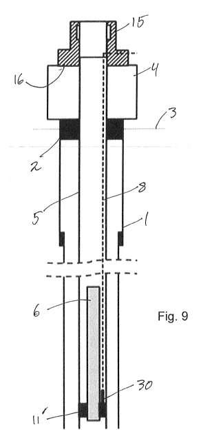
Figure 9 shows several of the same elements as in figures 1 and 2. The same
reference numbers have been retained for elements that are substantially
similar, such as the casing 1, the wellhead 2, the seabed 3, the Christmas
tree
4, the production tubing 5, the pump unit 6 and the power and signal cable 8.
The pump unit is landed in a docking station 11', which is similar to the
docking
station 11 of figure 2, but does not include a penetration of the production
tubing
5. The docking station 11' may nevertheless be installed together with the
production tubing. Alternatively, it may be installed at a later stage by
securing it
=
'ff*47176- AMENDED SHEET
.07107;2016
CA 02946951 2016-10-25
PCT/EP 2015 'M6
nnted 07-07-2016 15ff -67FTAKA PCT/ER2015/060
629
13
to the inside surface of the production tubing, as will be generally known to
the
person of skill.
The docking station includes a wet mate connector (see figure 5) and the cable
8 is connected to the docking station 11', via a weak link 30, at the inside
of the
production tubing 5. The cable 8 extends along the production tubing 5 on the
inside of the production tubing 5 from the docking station 11 through the
wellhead 2 and through the Christmas tree 4.
At the top of the Christmas tree is connected an adapter 15. This adapter is
shown in further detail in figure 4. The adapter 15 has a lower first
interface 16,
which is adapted to mate with a corresponding interface 17 on the top of the
Christmas tree 4. At the top of the adapter 15 is an upper second interface
18,
which is identical to the interface 17 on top of the Christmas tree 4.
The adapter 15 has a feed-through 19 for the power and signal cable 8, which
goes through the adapter and onwards to the surface or alternatively connects
with a wet mate connector on the outside of the adapter 15. The feed through
of
the cable 8 is in the lower part of the adapter 15 in order to reduce the
height of
the adapter 15 as much as possible.
= In addition, the adapter 15 has internal plug profiles 20 and 21. Thereby
the
adapter 1.5 serves two purposes; 1. to provide a feed-through for the cable 8
and 2. to provide the Christmas tree with plug profiles. The plug profiles,
which
can be for one, two or more plugs, to plug the bore of the tree and thereby
shutting in the well. Thereby, the adapter can serve to provide a tree 4 with
additional plug profiles or replace a damaged plug profile within the tree. If
one
plug profile is provided, the adapter must be for high pressure to maintain
two
barriers, otherwise a debris cap on the top of the adapter is sufficient. The
upper interface 18 of the adapter 15 is preferably of a standard profile, such
as
a H4 hub, to allow a workover riser system to be connected on top of the
adapter 15.
AMENDED SHEET
CA 02946951 2016-10-25
PCT/EP 2015
J-S'7iTnta10:97;201'
c-1=TA !PQT/EP-2915/069.,p29.
14
=
The adapter 15 can also be used for other applications, such as when extra
power and/or signals are needed in the well, and when it is considered
beneficial to install the equipment inside the production tubing to avoid
having to
change the completion. Such functions could be smart well functionality, such
as closing and opening parts of the reservoir to produce more oil/gas and less
water, extra valves for well control, monitoring systems, etc.
Figure 10 shows the docking station 11' in more detailed. It comprises a
docking sleeve 22 and a set of seal elements 23, 24, which serves to lock the
sleeve 22 against the inner surface of the production tubing 5, and to seal
the
annulus between the sleeve 22 and the production tubing 5. The sleeve 22
comprises an ESP landing shoulder 25, which is adapted to receive the pump
unit 6. It also comprises plug profiles 26, 27 that are adapted to receive a
plug
(not shown). The possibility of landing a plug in the docking station 11' will
be
described further below.
The docking station also comprises a wet mate connector 28, which is in this
embodiment is connected to a short cable length 29 and a weak link 30. The
weak link is in turn connected to the power and signal cable 8. Alternatively,
the
= weak link 30 may be on the docking station 11', as shown in figure 3.
An important feature of the docking station 11' design is that it does not
rely on
features within the completion tubing for it to be secured within the
production
tubing. Therefore, the docking station can be secured and sealed to the
production tubing by, for example, packers. The seal can either be permanent
or be releasable by control signals through the cable 8, or through other
= mechanical or chemical means, as known per se. The pump unit will be
landed
on the landing shoulder 25 and connected to the cable 8 through the wet mate
connector 28.
Figure 11 shows a situation in which a docking station 11' has been rendered
dysfunctional. This may be because the wet mate connector 28 is faulty,
because of damage to the ESP landing shoulder, or other flaws that result in
the
=
040 a
AMENDED SHEET
CA 02946951 2016-10-25
PCT/EP 2015
Printect:' 07707-2016 b'ff eiDAWAT PcTLER
201540g) .P29,
docking of the pump unit and connection thereof to the cable 8 no longer can
be
performed. In such a situation, the pump unit (not shown in figure 6) will be
recovered and a plug (not shown) may be landed and secured to the plug
profiles 26, 27 in the docking station 11' so that the flow through the
docking
5 station is blocked. The plug may be of a type that dissolves through
prolonged
contact with the well flow or due to an excess pressure on one side of the
plug,
=
e.g. plugs made of glass. Such plugs are well known in the art.
=
Before or after the plug has been set in the docking station, a pull is
exerted on
10 the cable 8 (see figure 5). The pull breaks the weak link 30, so that
only the
short cable length 29 remains. Then the cable 8 may be pulled out of the well
for re-use or replacement.
When the flow through the docking station has been blocked, a new docking
15 station 11" may be run into the production tubing 5 and secured to the
inner
surface of the production tubing 5. This docking station 11" may be identical
to
the faulty docking station 11', but may also be of an improved type. The cable
= that was recovered from the well, or alternatively a new cable, is
connected to
the new docking station 11" prior to its insertion into the well. The pump
unit that
20 was recovered from the first docking station 11' may be (if it has not
been
damaged) landed on the new docking station 11" and coupled to the cable 8
through the wet mate connector 28'. Thereafter the plug that has been set in
the
first docking station 11' will be removed by well-known means. As soon as the
plug has been removed, the operation of the ESP may resume.
As described above, if a new docking station is to be installed, the old one
can
be left in the well. The cable 8 can then be released and reused (if not
damaged) by performing the described over-pull on the cable 8 to break the
weak link 30. Since the old docking station has plug profiles 26, 27 to enable
easy plugging of the well at the correct location, this allows for retrieving
of the
cable 8 on a closed well.
The power and signal cable 8 (also termed ESP cable) may comprise power
lines, signal lines and hydraulic lines. According to the invention, the cable
8
'07=0'7-2616'
AMENDED SHEET
CA 02946951 2016-10-25
PCT/EP 2015/Pf",
1-?rin-ted: 0707=2016 15-ffeliA M-15
_ P.Cl/EP 2915/060 629,
16
can be routed from the adapter 15 or tree cap in several different ways.
However, it should be ensured that the cable runs close to the inner wall of
the
production tubing. This provides better space for running the pump unit into
and
out of the well, as well as other types of equipment. The cable 8 will also be
less
subject to forces from the well flow.
Figure 13 describes an embodiment of the present invention, which utilizes the
adapter 15 described above in combination with a pump unit 6 suspended on a
length of coiled tubing 7 from a hanger plug 31. This embodiment can be
beneficial for cases where it is difficult to get the correct hanger plug
profile to fit
the existing profiles in the Christmas tree 4. The adapter 15 will provide the
desired internal profile for a plug 9', from which the coiled tubing is
suspended.
The cable 8 may be going out through a tree cap 10' on top of the adapter 15
or
be fed through the side of the adapter 15, as described in connection with the
embodiment in figures 3 and 4. The embodiment of figure 7 may also be
beneficial over prior art for contingency operations, since an open water
workover system can land on the standard, e.g., H4, hub profile and gain well
- control before the hanger plug is removed.
A possible first time installation of the arrangement of the present invention
may
be as follows:
1. _ Plug the well using glass, step, or dissolvable plugs.
2. Circulate the well above the plugs with MEG (or similar types of fluids)
using, e.g., coiled tubing.
3. Land the adapter on the Christmas tree, with the cable and the docking
station attached.
4. Secure the docking station to the production tubing using, e.g., packers
or other means that acts against a slick tubing surface.
5. Land a workover system (open water or riserless system) on top of the
adapter.
6. Install the pump unit by landing it in the docking station.
7. Plug the adapter and install a debris cap, or a high-pressure tree cap.
8. Break the plugs, e.g., glass plugs, by pressurising through the
Christmas
iTeTlf)1,
Q7,07-201,.6,
AMENDED SHEET
CA 02946951 2016-10-25
PCT/EP 2015 /--`-`-'4)---',7-.2'7-7,1?-1.6
PESO P.4115 PC3/ER12015/060
17
= tree. Alternatively, let the plugs dissolve by contact with the well
flow, or
use explosives to dissolve the plugs.
When the pump unit needs to be replaced, the following procedure can be
used:
1. Install a workover system on top of the adapter (either an open water or
a
= riserless system).
2. Remove the plugs in the adapter.
3. Remove the pump unit using a wireline (preferably, the pump can be
retrieved in several parts to enable conventional wireline to be used and
to reduce the required lubricator length).
4. Install a new pump unit (preferably in several parts).
5. Set plugs in the adapter and install a debris cap or a high-pressure
cap.
if the docking station, cable or adapter should fail, the following procedure
can
be used:
1. Install workover system on top of the adapter (either open water or
riserless system)
2. Remove plugs in the adapter
3. Remove the pump unit using wireline (preferably, the pump can be
retrieved in several parts to enable conventional wireline to be used and
to reduce the required lubricator length).
4. Set glass or dissolvable plugs in the docking station to close the well.
5. Circulate the well by, e.g., MEG.
6.* Retrieve the adapter with a running tool, performing over-pull to
release
the cable at the weak link close to the docking station.
= 7. Perform the same operation as described for first time
installation.
The adaptor of the invention may include any feature or step herein described
or illustrated, in any operative combination, each such combination is an
embodiment of the invention.
The method of the invention may include any feature or step herein described
ar,a.TM
AMENDED SHEET
CA 02946951 2016-10-25
= PCT/EP 2015
Printed O7-O7-2016 ,DgsePAIV1pt .PCT/EP
2916/060 629
18
or illustrated, in any operative combination, each such combination is an
embodiment of the invention.
5'113
AMENDED SHEET