Note: Descriptions are shown in the official language in which they were submitted.
OIL-FREE COMPRESSOR CRANKCASE COOLING ARRANGEMENT
[0001]
BACKGROUND OF THE INVENTION
Fief dofittte Invention
[0002] The present disclosure relates to the field of air compressors adapted
for use on rail
vehicles for supplying compressed air to pneumatic units associated with the
rail vehicle and,
in particular, to an oil-free compressor crankcase cooling arrangement for
maintaining a safe
operating temperature within the crankcase.
Description of Related Art
[0003] By design, an oil-free compresSOr utiliks specially designed bearings
and
composite sealing materials to allow the air compressor to operate without
lubrication. An
example lone such oil-free air compressor for a rail vehicle is disclosed in
U.S. Patent
Application No. 14/030,588 to Kapadia et al. filed on September 18, 2013,
which may be
referred to. While the specialized components and materials allow the bearing
surfaces to
survive the internal loading within the air compressor without lubrications,
they do not benefit
from the cooling effects that are provided by a large sump of oil included in
an oil-flooded air
compressor. Therefore, internal cooling must be provided by alternative means.
[0004] There are two common preexisting methods for achieving improved cooling
within the
crankcase of an oil-free air compressor. The first method is to not seal the
crankcase and allow
air to naturally move into and out of the crankcase. The second method is to
draw the
compressor inlet air through the crankcase prior to being introduced into the
low pressure
cylinders for compression.
[0005] There are several deficiencies to using the first method of allowing
air to naturally
move into and out of the crankcase. By leaving the crankcase open to
atmosphere,
contamination and debris from the surrounding environment is easily pulled
into the
crankcase and increases the wear of the bearing surfaces, especially the
piston ring and
cylinder surf ace that are more prone to contamination. Further, the open
crankcase does not
create a cooling flow through the crankcase but, instead, creates a wafting-
like effect where
1
Date Recue/Date Received 2021-09-14
CA 02947306 2016-10-27
WO 201 Sri 72145 PCT/US2015/030154
the same air is pulled in and pushed out of the crankcase. This fails to cool
the internal
components of the air compressor as efficiently as possible since the hot air
pushed out of the
air compressor is not moved away from the crankcase.
[0006] There are also several deficiencies in using the second method of
drawing
compressor inlet air through the crankcase prior to being introduced into the
low pressure
cylinders for compression. By pulling all of the inlet air through the
crankcase before
entering the first stage of compression, the second method does create a
positive flow of fresh
air through the crankcase that can be directed from a single inlet point to a
single discharge
point. However, when the air is routed through the crankcase prior to entering
the first stage
cylinder, the temperature of the air entering the compressor is higher than it
would be if
pulled directly into the cylinder. This has at least two effects on the air
compressor. Firstly,
any or the heat taken out of the crankcase is put back into the compressor
within the primary
compressing flow path resulting in a higher first stage component temperature.
This will
= ultimately lead to a reduced life span for the inner air compressor
components. Further, the
increased temperature at the compressor inlet will result in a lower
compressor efficiency as
the inlet air temperature is inversely proportional to compressor efficiency.
Secondly, another
deficiency becomes apparent if the air compressor utilizes head unluaders that
are a conunon
means to operate an air compressor in an idle mode (not compressing air). In
this cycle, the
head unloaders typically act to mechanically hold the inlet valves open. 13y
holding the inlet
valves open, the air compressor continues to rotate but will not compress air,
as the
atmospheric air pulled in during the intake stroke is pushed back to
atmosphere through the
inlet valves during what is normally the compression stroke. As the same air
is cycled in and
out of the cylinder, the temperature of the air increases during the unloaded
cycle. If the
cylinder inlet air is routed through the crankcase prior to the atmospheric
connection, then the
air in the crankcase will be pulled into the Hist stage cylinder then pushed
back into the case
during the unloaded cycle. Therefore. the air temperature within the case will
increase in
temperature during the unloaded cycle similar to the air at the cylinder inlet
that increases
during the unloaded cycle in any common reciprocating air compressor with head
unionders.
Lastly. pulling the inlet air through the crankcase poor to introducing the
air into the first
stage cylinder may result in contamination from the crankcase being spread
into the first
stage cylinder. This includes wear debris from the piston rings and excess
grease released
from the scaled bearings that are both typical occurrences in an oil-free
compressor. This
contamination will wear on the valves of the air compressor and reduce the
life span of the
valves.
2
CA 02947306 2016-10-27
WO 2015/172145 PCT/US2015/030154
[0007] There is a current need for an oil-free air compressor crankcase
cooling
arrangement that increases the cooling of the crankcase without increasing the
contamination
= of the internal components of the crankcase. There is also a current need
for an oil-free air
compressor crankcase cooling arrangement that maximizes the life of the
internal dynamic
components while maintaining the crankcase at a safe operating temperature.
SUMMARY OF THE INVENTION
[0008] In one embodiment, an oil-free compressor crankcase cooling arrangement
for a rail
vehicle includes a compressor crankcase, at least one piston cylinder
supported in the
compressor crankcase, a crankshaft assembly supported by the compressor
crankcase and
linked to a piston of the at least one piston cylinder by a connecting rod, at
least one inlet,
valve supported on and in fluid communication with the compressor crankcase,
and at least
one outlet valve supported on and in fluid communication with the compressor
crankcase. A
cooling cross-flow of air is established between the at least one inlet valve
and the at least
one outlet valve to cool the compressor crankcase.
[0009] The at least one inlet valve and the at least one outlet valve may
include cheek
valves. A first nozzle may be positioned on the at least one inlet valve, and
a second nozzle
may be positioned on he at least one outlet valve. An inlet air filter may be
positioned on the
at least one inlet valve. The inlet air filter may protect the compressor
crankcase from
contamination and debris. An inlet air filter may be positioned on the first
nozzle of the at
least one inlet valve. The inlet air filter may protect the compressor
crankcase from
contamination and debris. The compressor crankcase may define a cavity for
housing the
crankshaft assembly. The cooling cross-flow of air may be directed through the
cavity of the
compressor crankcase from a first side of the compressor crankcase to an
opposing, second
side of the compressor crankcase. The at least one inlet valve may be
supported on a first side
of the compressor crankcase and the at least one outlet valve may be supported
on an
opposing, second side of the compressor crankcase. The at least one inlet
valve may be
opened as air is pulled into the compressor crankcase during an upstroke of
the at least one
piston cylinder. The at least one outlet valve may he opened as air is pushed
out of the
compressor crankcase during a downstroke of the at least one piston cylinder.
An unloader
valve assembly may be positioned on the at least one piston cylinder and may
be configured
to exhaust pressurized fluid from the al least one piston cylinder.
[00101 In another embodiment, a method of cooling an oil-free compressor
crankcase of a
= rail vehicle includes the steps of providing an oil-tree compressor
including a compressor
3
CA 02947306 2016-10-27
WO 2015/1721.15 PCT/US20151030154
crankcase, at least one piston cylinder supported in the compressor crankcase,
a crankshaft
assembly supported by the compressor crankcase and linked to a piston of the
at least one
piston cylinder by a connecting rod, at least one inlet valve supported on and
in fluid
communication with the compressor crankcase, and at least one outlet valve
supported on and
in fluid communication with the compressor crankcase; pulling air into the
compressor
crankcase via the at least one inlet valve: directing the air through the
compressor crankcase;
and pushing the air out of the compressor crankcase via the at least one
outlet valve.
[00111 A further step of the method may include opening the at least one inlet
valve during
an upstroke of the at least one piston cylinder. Air may be pulled into the
compressor
crankcase through the open inlet valve: A further step of the method may
include opening the
at least one outlet valve during a downstroke of the at least one piston
cylinder. Air may be
pushed out of the compressor crankcase through the open outlet valve. A
further step of the
method may include establishing a cooling cross-flow of air that is directed
from a first side
of the compressor crankcase, over the crankshaft assembly, and out of an
opposing, second
side of the compressor crankcase. The at least one inlet valve may be
supported on the first
side of the compressor crankcase. The at least one outlet valve may be
supported on the
opposing, second side of the compressor crankcase. A first nozzle may be
positioned on the
at least one inlet valve and a second nozzle may be positioned on the at least
one outlet valve.
Still further steps of the method may include providing an inlet air filter on
the at least one
inlet valve; and filtering the air that is pulled into the compressor
crankcase via the at least
one inlet valve using the inlet air filter. Further steps of the method may
include providing an
inlet air filler on the first nozzle of the at least one inlet valve; and
filtering the air that is
pulled lino the compressor crankcase via the at least one inlet valve using
the inlet air filter.
The at least one inlet valve and the at least one outlet valve may include
check valves. 'Me at
least one inlet valve may be supported on the compressor crankcase on a first
side of the at
least one piston cylinder. 'file at least one outlet valve may be supported on
the compressor
crankcase on an opposing second side of the at least one piston cylinder. A
further step of the
method may include providing an unloadcr valve assembly on the at least one
piston cylinder.
Still a further step of the method may include exhausting Fluid from the at
least one piston
cylinder via the unloader valve assembly.
[0012] Further details and advantages will be understood from the following
detailed
description read in conjunction with the accompanying drawings.
4
CA 02947306 2016-10-27
WO 20151172145 PCT/US2015/030154
BRIEF DESCRIPTION OF THE DRAWINGS
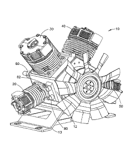
[0043] FIG. I is a front perspective view of an oil-lice air compressor
including a
crankcase cooling arrangement in accordance with this disclosure.
[00141 FIG. 2 is a rear perspective view of the oil-free air compressor of
FIG. 1.
[0015] FIG. 3 is a cross-sectional view of an oil-frec air compressor
including a crankcase
cooling arrangement in accordance with another embodiment of this disclosure.
[0016] FIG. 4 is another cross-sectional view of the oil-free air compressor
of FIG. 3 in
which a piston cylinder is on a downstroke.
DESCRIPTION OF THE PREFERRED EMBODIMENTS
[0017] For purposes of the description hereinafter, spatial orientation
terms, as used, shall
relate to the referenced embodiment as it is oriented in the accompanying
drawings. figures,
or otherwise described in the following detailed description. However, it is
to be understood
that the embodiments described hereinafter may assume many alternative
variations and
configurations. It is also to be understood that the specific components,
devices, features, and
operational sequences illustrated in the accompanying drawings, figures, or
otherwise
described herein are simply exemplary and should not be considered as
limiting.
[0018] The present disclosure is directed to, in general, an oil-free
compressor crankcase
cooling arrangement and, in particular, to an oil-free compressor crankcase
cooling
arrangement including at least two valves used to create a cross-flow of
cooling air through
the compressor crankcase. Certain preferred and non-limiting embodiments of
the
components of the cooling arrangement are illustrated in FIGS. 1-4.
[0019] Referring to FIGS. 1-4, an air compressor 10 according to one
embodiment of the
= disclosure is shown. As shown, the air compressor 10 is a multi-cylinder
air compressor 10
including a first piston cylinder 20, a second piston cylinder 30, a third
piston cylinder 40,
and a fourth piston cylinder 50. In ond embodiment, the air compressor 10 is
an oil-free air
compressor for a rail vehicle (not shown). The first piston cylinder 20, the
second piston
cylinder 30, the third piston cylinder 40, and the fourth piston cylinder 50
are supported by a
compressor housing or crankcase 12 and each are driven by a crankshaft
assembly 60
disposed within the compressor crankcase 12 and rotationally supported by the
compressor
crankcase 12. The compressor crankcase 12 may define a cavity 14 therein for
housing the
crankshaft assembly 60. The foregoing components of the air compressor 10 are
described in
detail herein. A inctimd of cooling the compressor crankcase 12 is described
in further detail
hereinbclow. The air compressor 10 may have a pentagonal-shaped cross-section.
A support
CA 02947306 2016-10-27
WO 2015/172145 PCT/US2015/030154
member 13 may be fastened to a bottom surface of the air compressor 10. The
support
member 13 may he used to mount the air compressor 10 on a locomotive or rail
vehicle (not
shown).
[0020] The first piston cylinder 20, the second piston cylinder 30, the
third piston cylinder
40, and the fourth piston cylinder 50 may be of substantially similar
construction with the
first piston cylinder 20 operating as the first cylinder, the second piston
cylinder 30 operating
as the second cylinder, the third piston cylinder 40 operating as the third
cylinder, and the
fourth piston cylinder 50 operating as the fourth cylinder in the multi-
cylinder air compressor
10. In one embodiment, the first piston cylinder 20, the second piston
cylinder 30, the third
piston cylinder 40, and the fourth piston cylinder 50 may be radially con
figured about a
longitudinal axis of the air compressor 10. The piston cylinders 20, 30, 40,
50 may interface
with an outer circumference of the air compressor 10.
[00211 As shown in FIGS. 3 and 4, the first piston cylinder 20 includes a
cylindrical
housing 21 that has a first end 22a adapted to be inserted into a
corresponding -opening, as
described herein, in the compressor crankcase 12 and a second end 22h. The
cylindrical
housing 21 is formed with a liana: 23 located proximal the first end 22a for
interfacing with
the exterior of the compressor crankcase 12. Heat-dissipating fins 24 may be
provided about
the cylindrical housing 21, and the cylindrical housing 21 may he formed of
any suitable
material providing sufficient strength and heat-dissipating characteristics
such as aluminum.
[0022] A cylinder head 25 is secured to the second end 22b of the
cylindrical housing 21.
The cylinder head 25 generally comprises an air connecting unit 26 and an
unloadcr cap 29
mechanically fastened to a top surface of the air connecting unit 26. The air
connecting unit
26 includes a first air channel 27 and a 'second air channel 28. The air
connecting unit 26 may
be formed of any suitable material providing sufficient strength and heat
transfer
characteristics such as aluminum. The unloader cap 29 houses art anloader
piston (not shown)
that mechanically holds the inlet side of the valve assembly (not shown) open
when
pneumatic signal is piloted to the valve assembly. It is also to be understood
that an electric
signal may be used to pilot the valve assembly. When activated, the air
compressor 10 will
continue to operate without compressing air, thereby cooling the cavity 14 of
the air
compressor 10.
[0023] The first piston cylinder 20 may further include a first piston 70
that is reciprocally
operable within the cylindrical housing 21. The piston 70 includes a first end
72a and a
second end 720. and is made of any suitable material providing sufficient
strength and heat
transfer characteristics such as aluminum. The piston 70 is operatively
connected to the
6
CA 02947306 2016-10-27
WO 2015/172145 PCT/US2015/030154
crankshaft assembly 60 via a connecting rod 74. A cavity 76 may be defined in
the
cylindrical housing 21 to hold the piston 70. In operation, die piston 70
operates in a
reciprocating movement which is generated via rotation of the crankshaft
assembly 60. Air is
drawn into the cavity 76 of the cylindrical housing 21 of the first piston
cylinder 20 via one of
the air channels 27, 28 as a result of the downward movement of the piston 70.
A valve
assembly (not shown) may be associated with the cylinder head 25 and includes
a portion that
is opened during the downward movement of the piston 70, drawing air into the
cylindrical
housing 21, and closes during the upward movement. Further, the valve assembly
may
include another portion that closes during the downward movement of the piston
70 and
opens during the upward movement of the piston 70. whereby air in the
cylindrical housing
21 is compressed and is guided out of the cylindrical housing 21.
100241 As noted previously, the second piston cylinder 30, the third piston
cylinder 40, and
the fourth piston cylinder 50 have ir substantially similar construction to
the first piston
cylinder 20.
[0025] Referring to FIGS. 1 and 2, a first inlet valve 80 and a second
inlet valve 82 are
supported on a first side of the compressor crankcase 12. A first outlet valve
90 and a second
outlet valve 92 may be supported on an opposing, second side of the compressor
crankcase
12. The first inlet valve 80, the second inlet valve Si the first OW let valve
90. and the second
outlet valve 92 may be in fluid communication with the compressor crankcase
12. In one
embodiment, the first inlet valve 80, the second inlet valve 82, the first
outlet valve 90, and
the second outlet valve 92 may be check valves. In one embodiment, the first
inlet valve 80,
the second inlet valve 82, the first outlet valve 90, and the second outlet
valve 92 may he ball-
type check valves. In another embodiment, the first inlet valve 80, the second
inlet valve 82,
the first outlet valve 90, and the second outlet valve 92 may include an
elastomer valve
element (not shown) positioned between a seat (not shown) and guide member
(not shown).
This type of cheek valve is commonly known as a "flapper" style check valve.
It is to be
understood, however, that the use of alternative typii.s of check valves arc
contemplated, such
as a diaphragm check valve, a swine check valve, and a lift check valve, among
others. In
one embodiment, the first inlet valve 80, the second inlet valve 82, the first
outlet valve 90,
and the second outlet valve 92 may be used to establish a cooling cross-flow
of air 16
between one another to cool the compressor crankcase 12. Although only two
inlet valves
and two outlet valves are shown in the drawings, it is contemplated that fewer
or additional
inlet valves and outlet valves !nay be supported on the compressor crankcase
12 to provide a
reduced or greater amount of air for the cooling cross-flow 16 through the
compressor
7
CA 02947306 2016-10-27
WO 2015/172145 PCT/US2015/030454
crankcase 12. As shown in FIGS. .1 and 2, the first inlet valve 80 and the
second inlet valve
82 may he positioned parallel to one. another, and the first outlet valve 90
and the second
outlet valve 90 may be positioned parallel to one another. It is also to be
understood,
however, that die first inlet valve 80 and the second inlet valve 82 may he
positioned in series
with one another, and the first outlet valve 90 and the second outlet valve 92
may be
positioned in series with one another. The configuration of the valves may be
used according
to the capacity needed in the air compressor 10 and to provide redundancy.
100261 In one embodiment, the first inlet valve 80 and the second inlet valve
82 may he
supported on a lower portion of the compressor crankcase 12. The first outlet
valve 90 and
the second outlet valve 92 may be supported on an opposing, lower portion of
the compressor
crankcase 12. In one embodiment, the first inlet valve 80 and the second inlet
valve 82 may
be supported on the compressor crankcase 12 adjacent the first piston cylinder
20. The first
outlet valve 90 and the second outlet valve 92 may be supported on the
compressor crankcase
12 adjacent the fourth piston cylinder 50. Using this arrangement of the first
inlet valve 80,
the second inlet valve 82, the first outlet valve 90, and the second outlet
valve 92, the cooling
cross-flow of air 16 may be directed through the cavity 14 of the compressor
crankcase 12
from the first side of the compressor crankcase 12 to the opposing, second
side of the
compressor crankcase 12. The cooling cross-flow of air 16 is directed over the
crankshaft
assembly 60 to provide cooling for the components of the crankshaft assembly
60 and the
compressor crankcase 12. To establish this cooling cross-flow of air 16 in the
compressor
crankcase 11 air is pulled into the compressor crankcase 12 via the first
inlet valve 80 and
the second inlet valve 82. During an upstroke of the piston 70 in the
cylindrical housing 21 of
the first piston cylinder 20, the first inlet valve 80 and the second inlet
valve 82 are opened by
the air that is pulled into the compressor crankcase 12. The first inlet valve
80 and the second
inlet valve 82 may be selected and/or adjusted according to the desired amount
at air pressure
that is necessary to open the first inlet valve 80 and the second inlet valve
82. During the
upstroke or the piston 70 in the cylindrical housing 21 of the first piston
cylinder 20, the First
outlet valve 90 and the second outlet valve 92 are kept closed. In one
embodiment, the
cooling cross-flow of air 16 is then directed diagonally through the cavity 14
of the crankcase
assembly 12 towards the first outlet valve 90 and the second outlet valve 92.
During a
downstroke of the piston 70 in the cylindrical housing 21 of the first piston
cylinder 20, the
cooling cross-flow of air .16 is pushed out of the first outlet valve 90 and
the second outlet
valve 92 to atmosphere. During the downstroke of the piston 70 in the
cylindrical housing 21
of the first piston cylinder 20, the first inlet valve 80 and the second inlet
valve 82 are kept
8
CA 02947306 2016-10-27
WO 2015/1721.15 PCT/US2015/030154
closed. The first outlet valve 90 and the second outlet valve 92 may be
selected and/or
adjusted according to the desired amount of air pressure that is necessary to
open the first
outlet valve 90 and the second outlet valve 92. The total change of volume in
the air
compressor 10 is a summation of all of the piston movement within the air
compressor JO.
Therefore, it is the total volume changed by reciprocating movement of the
first piston
cylinder 20, the second piston cylinder 30, the third piston cylinder 40, and
the fourth piston
cylinder 50, combined. 'Ibis configuration and operation of the air compressor
10 ensures that
the maximum amount of crankcase volume change is achieved without sacrificing
other air
compressor 10 characteristics. By combining the change in volume of all of the
piston
cylinders 20, 30, 40, 50, during rotation of the crankshaft assembly 60, a
maximum volume
of air inay be used to coot the air compressor 10.
= [0027] While FIGS. 1 and 2 depict the use of two inlet valves 80. 82 and
two outlet valves
90. 92, it is also to he understood that only one inlet valve 80 and one
outlet valve 90 may he
used, as shown in FIGS. 3 and 4.
[0028] Referring now to FIGS. 3 and 4, a first nozzle 100 may be positioned on
the first
inlet valve 80 and/or the second inlet valve 82. The first nozzle 100 may be
used to direct the
flow of air into the first inlet valve 80 and/or the second inlet valve 82
during the upstroke of
the piston 70 in the cylindrical housing 21 of the first piston cylinder 20. A
second nozzle 110
may be positioned on the first outlet valve 90 and/or the second outlet valve
92. The second
nozzle 110 may be used to direct the flow away from the compressor crankcase
12 to avoid
directing the exhausted hot air back, towards the compressor crankcase 12. It
is to be
understood that different types of nozzles may be used in place of the first
nozzle 100 and the
second nozzle 110, such as nozzles with a wider or narrower inlet or nozzles
with a different
cross-sectional shape. I murther, although FIGS. 3 and 4 only depict the use
of the first inlet
valve 80 and the first outlet valve 90, it is to be understood that the second
inlet valve 82 and
the second outlet valve 92 may be used as well. Nozzles may also be positioned
on these
valves as well.
[0029] With continued reference to FIGS. 3 and 4, an inlet air filter 120 may
be
operatively connected to the first inlet valve 80 and/or the second inlet
valve 82. The inlet air
filter 120 may be any standard inlet air filter commercially available that
provides a screening
function to remove contamination and debris front the air that is pulled into
the compressor
crankcase 12 through the first inlet valve 80 and/or the second inlet valve
82. The inlet air
filter 120 provides filtering capabilities to the air compressor 10 by
removing debris and other
contamination that may create wear on the crankshaft assembly 60 and
components of the
9
CA 02947306 2016-10-27
WO 2015/172145 PCT/US2015/030154
piston cylinders 20, 30, 40. 50. In one embodiment, the inlet air filter 120
may he positioned
on an end of the first nozzle 100. During use of the air compressor 10, air is
pulled into the
cavity 14 of the compressor crankcase 12 first through the inlet air filter
120, then through the =
first nozzle 100, and finally through the first inlet valve 80 and/or the
second inlet valve 82.
1.00301 Although a
description of the first inlet valve SO and the first outlet valve 90 being
operatively positioned with the first piston cylinder 20 is provided, one of
skill in the art will
recognin that the first inlet valve 80 and the first outlet valve 90 may also
be operatively
positioned at different positions on the compressor crankcase 12, The first
inlet valve 80 and
= the first outlet valve 90 may he operatively positioned with another
piston cylinder 30, 40, 50.
Further, the first inlet valve 80 and the first outlet valve 90 may be
positioned adjacent the
first piston cylinder 20 and the fourth piston cylinder 50, respectively. The
arrangement of the
inlet valve 80 and the outlet valve 90 would be substantially similar to the
arrangement
described above in connection with the first piston cylinder 20.
[003]] A method of cooling the compressor crankcase 12 is also described
herein with
reference to FIGS. 3 and 4. In one embodiment, this method includes the step
of providing an
air compressor 10 as described hereinabove, During use of the cooling method,
air front
at it is pulled into the
cavity 14 of the compressor crankcase 12 via the first inlet valve
80. The air is used as a cooling cross-flow of air 16 that is directed front
the first inlet valve -
80 to the first outlet valve 90. The cooling cross-flow of air 16 is directed
through the cavity
14 of the compressor crankcase 12, thereby flowing over the components of the
crankshaft
assembly 60 and the piston cylinders 20, 30. 40, 50. Alter the cooling cross-
flow of air 16 is
directed through the cavity 14 of the compressor crankcase 12, the air is
pushed out of the
compressor crankcase 12 via the first outlet valve 90. As the air is directed
over the
crankshaft assembly 60 and the components of the piston cylinders 20, 30, 40,
50. the
components are cooled by the air. The heat generated by the components is
transferred to the
cooling cross-flow of air 16 and carried out of the compressor crankcase 12.
In one
embodiment, the first inlet valve 80 and the first outlet valve 90 may be
check valves, as
described hereinabove. The first inlet valve 80 may be supported on a first
side of the
compressor crankcase 12. The first outlet valve 90 may he supported on an
opposing, second
side of the compressor crankcase 12.
[00321 As the pistons 20, 30, 40, 50 of the air compressor 10 move in and out
of their
respective piston cylinders, the total volume within the compressor crankcase
12 changes
through a single rotation of the crankshaft assembly 60 provided the cylinders
20, 30, 40, 50
are not perfectly out of phase and of the same diameter. In one embodiment,
the first inlet
CA 02917306 2016-10-27
= µVO 2015/172145
PC:T/11:32015/030154
valve 80 is opened during an upstroke of the piston 70 in the cylindrical
housing 21 of the
first piston cylinder 20. The pressnre exerteci by the air (hat is pulled into
the compressor
crankcase 12 pushes open the first inlet valve 80. In one embodiment, air may
be pulled into
the compressor crankcase 12 via the first inlet valve 80 until a alaXillaall
volume of the
compressor crankcase 12 is filled. In one einhcaiiment, the first outlet valve
90 may be
opened during a downstroke of the piston 70 in the cylindrical housing 21 of
the first piston
cylinder 20. The pressure exerted by he air that is pushed throne!' and out of
the cavity 14 of =
the compressor crankcase 12 pusties open the first outlet valve 90. thereby
allowing the air to
vent to atmosphere. In one embodiment. air is pushed out of the compressor
crankcase 12 via
(he first outlet valve 90 until a minimum volume of the compressor crankcare
12 remains.
Using the described method, the cooling cross-flow of air 16 may be directed
from a first side
of the compressor crankcase 12, over the crankshaft assembly 60. and out of an
o)posing.
= second side of the compressor crankcase 12. In this embodiment. the first
inlet valve 80 is
supported on the first side of the compressor crankcase 12 and the first
outlet valve 90 is
supported on the. opposing. second Side of the compressor crankcase 12.
Although the
operation of the cooling method of the air compressor 10 is described in
relation to the first
piston cylinder 20. it is to he understood drat Ore cording method is a
cumulative effect of the
reciprocating movement of all of the piston cyllttders 20, 30, 40, 50 that
creates the cooling
crosa-flow of air 16. The second piston eylindt:r 59, the third piston
cylinder 40, and the
fourth piston cylinder 50 operating in a similar manner co the first piston
cylinder 20 to create
the cross-flow of air It,. it is also to he unds!..stood that the first inlet
valve 80 and the first
outlet valve 90 may be positioned near one of the second piston cylinder 30.
ihe third piston
cylinder 40, or the fourth piston cylinder 50 to provide the same cooling
effect in the air
compressor 10.
[0033] In one embodiment of the method, the first nonle 100 may be posit icmed
on the
first inlet valve 80 snd the second nozzle 110 nury he positioned on the first
outlet valve 90.
The first nozzle 100 may he configured to direct the air rrola atmosphere into
the first inlet
valve 80. The second nozzle .110 may he configured to direct the air from the
first outlet
valve 90 to atmosphere. The second trozzle 110 (lirocts the air, whose
temperature has risen
duc to the heat transferred from the compressor crt.ttc:tse !2 components,
away front the
compressor crunitcas.: :2 to rtinosphere.
10034'1 In another
embodiment oi lite method, the inlet air fiiter 120 nary be operatively
connected to the first inlet valve The nir that is
pulled ion-, the first inlet valve 80 may he
filtered by the inlet air filter 120 to rµantwe any contamination or deltris
from the air, se as not
LI
CA 02947306 2016-10-27
WO 2015/172145 = PCT/US2015/030154
to contaminate or wear the inner components of the air compressor 10. The
inlet air filter 120
may also be positioned on an end of the first nozzle 100 connected to the
first inlet valve 80.
[00351 As explained hereinabove, although a description of a method of
using the first inlet
valve 80 and the first outlet valve 90 with the first piston cylinder 20 to
cool the inner
components of the compressor crankcase 12 is provided, one of skill in the art
will recognize
that the method may also be performed at different positions on the compressor
crankcase 11
The first inlet valve 80 and the first outlet valve 90 may be operatively
positioned with
another piston cylinder 30, 40, 50. Alternatively, the first inlet valve 80
and the first outlet
valve 90 may be positioned adjacent to the first piston cylinder 20 and the
fourth piston
cylinder 50, respectively. It is also to be understood that the second inlet
valve 82 and the
second outlet valve 92 may be used to create a larger cooling cross-flow of
air 16 through the
compressor crankcase 12. The arrangement and operation of the inlet valve 80
and the outlet
valve 90 would be substantially similar to the arrangement described above in
connection
with the first piston cylinder 20.
[0036] By using the method described hereinabove, there is no effect on the
inlet air
temperatures that are provided. Therelbre, the first inlet valve 80 and the
first outlet valve 90
are able to provide a directed positive flow through the compressor crankcase
12 without
reducing the overall efficiency of the air compressor 10, unlike if the inlet
air was first routed
through the compressor crankcase 12. Further, the air at the first inlet valve
80 will not be
pre-heated upon entering the compressor crankcase 12, resulting in lower first
stage
temperatures. The air compressor 10 described hereinabove includes a multi-
cylinder
arrangement that maximizes the total change in the compressor crankcase 12
volume per
revolution of the crankshaft assembly 60, without sacrificing the dynamic
balance of the air
compressor 10. In addition, the total crankshaft assembly 60 torque pulse per
each revolution
is reduced, while still maintaining a small overall size envelope for the air
compressor 10.
100371 While an embodiment of an oil-free compressor crankcase cooling
arrangement is
shown in the accompanying Figures and described hereinabove in detail, other
embodiments
will be apparent to, and readily made by, those skilled in the art without
departing from the
scope and spirit of the invention. Accordingly, the foregoing description is
intended to he
illustrative rather than restrictive. The invention described hereinabove is
defined by the
appended claims and all changes to the invention that fall within the meaning
and the range
of the equivalency of the claims are to be embraced within their scope.
12