Note: Descriptions are shown in the official language in which they were submitted.
CA 02947321 2016-10-28
WO 2015/164977 PCT/CA2015/050372
MANIFOLD STRUCTURE FOR RE-DIRECTING A FLUID STREAM
CROSS-REFERENCE TO RELATED APPLICATION
[0001] This application claims priority to and the benefit of United
States
Provisional Patent Application No. 61/987,570 filed May 2, 2014 under the
title
"FLOW-PROMOTING MANIFOLD STRUCTURE FOR A HEAT EXCHANGER APPARATUS
AND A HEAT EXCHANGER APPARATUS INCORPORATING SAME". The content of the
above patent application is hereby expressly incorporated by reference into
the
detailed description of the present application.
TECHNICAL FIELD
[0002] The invention relates to a manifold structure for re-directing a
fluid
stream as well as to a manifold structure capable of promoting flow
distribution of
an incoming fluid stream to additional components within an apparatus or
system.
In particular, the invention relates to a manifold structure for re-directing
an
incoming and/or outgoing fluid stream and promoting more even flow
distribution
through a heat exchanger apparatus.
BACKGROUND
[0003] Heat exchangers arranged within fluid housings are known and are
used for a variety of applications. In general, heat exchangers are often
arranged
within a fluid housing in order to either immerse the heat exchanger within a
fluid
or to allow a fluid to flow through the housing across the heat exchanger
thereby
bringing at least two different fluids into heat transfer relationship with
one
another. The arrangement of the fluid inlets/outlets on the housing and the
overall
structure of the housing can affect the fluid flow over and/or through the
heat
exchanger thereby impacting the overall efficiency and/or performance of the
1
CA 02947321 2016-10-28
WO 2015/164977 PCT/CA2015/050372
overall heat exchanger apparatus. The arrangement and/or positioning of the
heat
exchanger within an outer housing can also affect the overall performance of
the
apparatus in general. This is often apparent when fluid enters the housing in
a
different direction to which it exits the housing (or vice versa) as
directional
changes can often result in energy losses and/or increases in pressure drops
across
the corresponding apparatus. Additionally, the specific location of the fluid
inlet on
the housing can have an effect as to whether the incoming fluid stream is
evenly
and/or sufficiently distributed through the fluid channels associated with the
corresponding heat exchanger or other apparatus thereby affecting the overall
efficiency and performance of the apparatus. Accordingly, the manner in which
incoming fluid is directed towards and/or discharged from an enclosed heat
exchanger or other suitable component or apparatus is an important
consideration
when trying to optimize overall heat transfer performance.
[0004] Accordingly, there is a need for improved manifold structures for
directing and/or distributing incoming and/or outgoing fluid streams,
especially in
instances where fluid enters a heat exchanger or other suitable apparatus at a
different direction to the direction in which it exits the overall assembly or
vice
versa .
SUMMARY OF THE PRESENT DISCLOSURE
[0005] In accordance with an exemplary embodiment of the present
disclosure there is provided a manifold structure comprising a manifold cavity
for
receiving a fluid; a first fluid opening in fluid communication with said
manifold
cavity, said first fluid opening having a flow axis oriented in a first
direction, said
first fluid opening located at a first end of said manifold cavity for
inletting or
outletting said fluid to or from said manifold cavity in said first direction;
a second
fluid opening in fluid communication with said manifold cavity, said second
fluid
opening having a flow axis oriented in a second direction that is generally
perpendicular to said first direction, said second fluid opening arranged at a
second
2
CA 02947321 2016-10-28
WO 2015/164977 PCT/CA2015/050372
end of said manifold cavity for inletting or outletting said fluid to or from
said
manifold cavity in said second direction; a first curved surface forming a
bottom
portion of said manifold cavity generally opposite to said first fluid
opening, said
first curved surface having a concave curvature; wherein said first curved
surface is
a flow diverting surface for redirecting fluid flow from either said first or
second
direction to the other of said first or second direction.
[0006] In accordance with another exemplary embodiment of the present
disclosure there is provided a heat exchanger apparatus, comprising: a housing
defining first manifold cavity and a second manifold cavity and a flow passage
interconnecting said first manifold cavity and said second manifold cavity; a
first
fluid opening formed in said housing in fluid communication with said first
manifold
cavity and having a flow axis oriented in a first direction; a second fluid
opening
formed in said housing in fluid communication with said second manifold cavity
and
having a flow axis oriented in a second direction; a heat exchanger located
within
the flow passage between the first manifold cavity and the second manifold
cavity,
the heat exchanger having a plurality of first fluid channels for transmitting
a first
fluid therethrough in said second direction, and a plurality of second fluid
channels
for transmitting a second fluid therethrough, the heat exchanger having a
first end
in fluid communication with said first manifold cavity and a second end in
fluid
communication with said second manifold cavity; a first curved surface forming
a
base end of said first manifold cavity generally opposite to said first fluid
opening,
said first curved surface having a first portion extending towards said first
fluid
opening and a second portion extending away from said fluid inlet and defining
a
concave curvature therebetween; wherein said first curved surface is a flow
diverting surface for redirecting fluid flow between one of said first fluid
opening or
said second fluid opening and the other of said first fluid opening and said
second
fluid opening from said first or second direction to the other of said first
or second
direction for transmission to or from said first fluid channels of said heat
exchanger.
3
CA 02947321 2016-10-28
WO 2015/164977 PCT/CA2015/050372
BRIEF DESCRIPTION OF THE DRAWINGS
[0007] Reference will now be made, by way of example, to the accompanying
drawings which show example embodiments of the present application, and in
which:
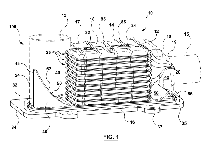
[0008] Figure 1 is a perspective view of a heat exchanger apparatus
according to an example embodiment of the present disclosure;
[0009] Figure 2 is a top view of the heat exchanger apparatus of Figure
1;
[0010] Figure 3 cross-sectional view of the heat exchanger apparatus of
Figure 1 taken along the longitudinal axis of the heat exchanger apparatus;
[0011] Figure 3A is a perspective view of the heat exchanger apparatus of
Figure 1 with a control device mounted thereon;
[0012] Figure 4 is a top, perspective view of a heat exchanger apparatus
according to another example embodiment of the present disclosure;
[0013] Figure 5 is a top, perspective view of the base plate of the heat
exchanger apparatus of Figure 4;
[0014] Figure 6 is a cross-sectional view of the manifold structure of
the heat
exchanger apparatus of Figure 4 taken along an axis perpendicular to the
longitudinal axis of the heat exchanger apparatus;
[0015] Figure 7 is a top, perspective view of a component of the manifold
structure of Figure 6;
[0016] Figure 8 is a top, perspective view of the cover portion of the
heat
exchanger apparatus of Figure 4;
[0017] Figure 9 is a side view of the cover portion of Figure 8;
[0018] Figure 10 is a bottom, perspective view of the cover portion of
Figure
7;
4
CA 02947321 2016-10-28
WO 2015/164977 PCT/CA2015/050372
[0019] Figure 11 is a schematic illustration of fluid flow through the
heat
exchanger apparatus of Figure 1;
[0020] Figure 11A is a schematic illustration of an alternate fluid flow
path
through the heat exchanger apparatus of Figure 1 where the first manifold
cavity
functions as an outlet manifold;
[0021] Figure 12 is a schematic illustration of fluid flow through the
heat
exchanger apparatus of Figure 4;
[0022] Figure 12A is a schematic illustration of an alternate fluid flow
through the heat exchanger apparatus of Figure 4 where the first manifold
cavity
functions as an outlet manifold;
[0023] Figure 13 is a fluid model of the heat exchanger apparatus
according
to the present disclosure illustrating the fluid flow through the apparatus.
[0024] Figure 14 is a top, perspective view of a heat exchanger apparatus
according to another example embodiment of the present disclosure;
[0025] Figure 15 is a cross-sectional view of the manifold structure of
the
heat exchanger apparatus of Figure 14 taken along an axis perpendicular to the
longitudinal axis of the heat exchanger apparatus;
[0026] Figure 16 is a top, perspective view of the cover portion of the
heat
exchanger apparatus of Figure 14; and
[0027] Figure 17 is a top, perspective view of the base plate of the heat
exchanger apparatus of Figure 14.
[0028] Similar reference numerals may have been used in different figures
to
denote similar components.
CA 02947321 2016-10-28
WO 2015/164977 PCT/CA2015/050372
DESCRIPTION OF EXAMPLE EMBODIMENTS
[0029] Referring now to Figures 1-3 there is shown an exemplary heat
exchanger apparatus 10 incorporating a manifold structure 100 according to an
example embodiment of the present disclosure. For ease of reference, the
example
embodiment will be described in relation to a heat exchanger apparatus however
it
will be understood that the technology described may be used in connection
with
other fluid transmitting devices such as mass transfer or humidifier devices,
for
example, depending on the particular application.
[0030] As shown, the heat exchanger apparatus 10 comprises a heat
exchanger (or fluid transmitting device) 12 arranged within a flow box or
outer
housing 14. The flow box 14 is generally in the form of an external casing or
housing comprised of a base plate 16 and a cover portion 18 positioned on top
of
base plate 16 and enclosing heat exchanger 12 within the combined structure.
While the subject exemplary embodiment is described in relation to a heat
exchanger 12 being enclosed within the assembly it will be understood, as set
out
above that the manifold structure 100 and/or flow box 14 may also be used in
conjunction with other fluid transmitting devices, such as for example a mass
transfer device or humidifier. Accordingly, it will be understood that the
present
disclosure is not intended to be limited to use with heat exchangers and that
other
devices having fluid delivered to and discharged therefrom are contemplated
within
the scope of the present disclosure.
[0031] Flow box 14 defines a fluid inlet or first fluid opening 13
generally at
one end of the flow box 14 in the top surface 17 of the cover portion 18 and a
fluid
outlet or second fluid opening 15 arranged at an opposite end of the flow box
14 in
an end wall 19 of the cover portion 18 of the flow box 14. Accordingly, the
first
fluid opening 13 has a flow axis generally perpendicular to the longitudinal
axis of
the flow box 14 and/or the heat exchanger or fluid transmitting device 12
enclosed
within the flow box 14. The second fluid opening 15 is formed in the end wall
19 of
the flow box 14 at the opposite end to the first fluid opening 13 and,
therefore, has
a flow axis generally perpendicular to that of the first fluid opening 13 and
generally
6
CA 02947321 2016-10-28
WO 2015/164977 PCT/CA2015/050372
parallel to and/or in-line with the longitudinal axis of the flow box 14
and/or the
heat exchanger 12 (or fluid transmitting device) housed within the flow box
14. In
the subject exemplary embodiment the first fluid opening 13 functions as an
inlet
opening while the second fluid opening 15 functions as an outlet opening
however it
will be understood that the reverse flow direction is also possible.
Accordingly, in
operation, a first heat exchange fluid enters the heat exchanger apparatus 10
through first fluid opening 13 and is directed through the manifold structure
100 so
as to be brought into contact and heat exchange relationship with the heat
exchanger 12 housed within the flow box 14. The fluid flows through heat
exchanger 12 in heat transfer relationship with a second fluid flowing through
the
heat exchanger 12 before exiting the heat exchanger 12 and heat exchanger
apparatus 10 through the second fluid opening 15. The overall fluid flow
through
the flow box 14 therefore undergoes a change in flow direction of at least
about 90
degrees between the first fluid opening 13 and the second fluid opening 15.
The
material of construction of the base plate 16 and cover portion 18 of the flow
box
14 is not particularly limited and may be selected depending upon the
particular
application of the heat exchanger apparatus 10. In some embodiments, the cover
portion 18 and/or base plate 16 may be formed of suitable plastic material.
[0032] Heat exchanger (or fluid transmitting device) 12 may be of any
suitable form and, in the subject exemplary embodiment, is in the form of a
stacked-plate heat exchanger comprising a plurality of spaced-apart, stacked
tube
members 20 that each defines an internal fluid flow passage 21 for the flow of
second heat exchange fluid therethrough, as shown for instance in Figure 3.
Each
tube member 20 has a fluid inlet opening and a fluid outlet opening in
communication with the internal fluid flow passage 21, the fluid inlet opening
and
fluid outlet opening of adjacent tube members 20 being aligned so as to define
a
fluid inlet manifold 22 and a fluid outlet manifold 24 (shown schematically in
Figures 1 and 2). Corresponding openings 26, 28 (shown in Figure 5) may be
formed in the base plate 16 (or in the cover portion 18 depending on the
particular
application) of the heat exchanger apparatus 10 to allow for suitable fluid
inlet/outlet fittings (not shown) to be mounted in communication with the
fluid inlet
7
CA 02947321 2016-10-28
WO 2015/164977 PCT/CA2015/050372
and outlet manifolds 22, 24 for inletting and discharging the second fluid
through
the heat exchanger 12. In some embodiments, the heat exchanger apparatus 10
may be mounted directly in fluid communication with a corresponding fluid
source
(e.g. such as the housing of an automobile system component). Alternatively,
depending upon the exact positioning/arrangement of the inlet and outlet
manifolds
22, 24 of heat exchanger 12, the inlet and outlet openings 26, 28 may be
formed in
the cover portion 18 of the flow box 14.
[0033] The spaces formed between the spaced-apart, stacked tubular
members 20 form a second set of fluid passages 25 for the flow of the first
heat
exchange fluid entering the heat exchanger apparatus 10 through first fluid
opening
13 to flow through the heat exchanger 12 thereby bringing the first heat
exchange
fluid into heat exchange relationship with the second heat exchange fluid
flowing
through the enclosed first set of fluid passages 21. Heat transfer augmenting
devices, such as fins, may be located between the stacked, tube members in
order
to improve heat exchange efficiency and/or increase overall strength of the
heat
exchanger structure. Alternatively, the stacked tube members 20 may be formed
with dimples, ribs or other protuberances 27 formed on the outer or inner
surfaces
of the tube members 20 in order to achieve similar effects. Turbulizers or
other
known devices such as dimples or ribs 27 may also be arranged or formed within
the internal fluid flow passages 21 in order to increase heat transfer in
accordance
with principles known in the art. In some embodiments, the tube members 20 may
be formed as a unitary structure while in other embodiments they may be formed
from mating plate pairs.
[0034] Heat exchanger (or fluid transmitting device) 12 is arranged so as
to
be enclosed within flow box 14. Heat exchanger 12 is positioned on a generally
planar central portion 30 of the inner surface 32 of base plate 16 with the
cover
portion 18 of the flow box 14 being arranged over-top of the heat exchanger 12
and sealing against the upper or inner surface 32 of the base plate 16. In
some
embodiments the base plate 16 may be formed with a raised lip, or peripheral
rim
35 that is inwardly disposed from the peripheral edge 34 of the base plate 16
to
8
CA 02947321 2016-10-28
WO 2015/164977 PCT/CA2015/050372
provide a sealing surface for engaging with the open end 36 of the cover
portion
18. Accordingly, a portion of the base plate 16 extends outwardly beyond the
perimeter defined by the cover portion 18 to provide additional mounting
surface, if
required. Mounting holes 37 may also be formed at spaced apart intervals
around
the base plate 16 to assist with mounting and/or securing of the heat
exchanger
apparatus 10 to a corresponding component within an overall system, for
example.
[0035] A first manifold cavity or space 40 is defined within the cover
portion
18 at the inlet or first end of the flow box 14, the first manifold cavity
being
generally aligned with first fluid opening 13 and being open to and in fluid
communication with the open ends of the second set of fluid passages 25 formed
in
heat exchanger 12. A second manifold cavity or space 42 is defined within the
cover portion 18 at the outlet end of the flow box 14, the second manifold
cavity 42
being in fluid communication with the outlet ends of the second set of fluid
passages 25 in the heat exchanger 12 for receiving the first fluid as it exits
the
second set of fluid passages 25 before being discharged from the heat
exchanger
apparatus 10 through second fluid opening 15. In general, it is desirable for
incoming fluid to be directed towards the heat exchanger 12 over a large area
of
the inlet end of the heat exchanger 12 to ensure even and/or optimized fluid
distribution through fluid channels 25 of the heat exchanger 12. In order to
promote fluid flow towards a large area of the inlet end of heat exchanger 12,
first
fluid opening 13 is arranged slightly offset with respect to the inlet end of
heat
exchanger 12 or longitudinal axis of the heat exchanger apparatus as shown
most
clearly in Figure 2. As illustrated in the drawings, first fluid opening 13 is
formed in
the cover portion 18 so as to be positioned at the lower left hand corner of
the inlet
end of heat exchanger 12 (when viewed from above). Cover portion 18 is also
shaped and contoured in order to promote fluid flow from the first fluid
opening 13,
located generally at one corner of the heat exchanger 12, across the entire
end face
or inlet end of the heat exchanger 12. More specifically, rather than the
cover
portion 18 having a generally rectangular, dome-shaped structure, the inlet
end of
the cover portion 18, as shown in the top view of Figure 2, is contoured so as
to
taper inwardly around the first fluid opening 13 before extending or tapering
9
CA 02947321 2016-10-28
WO 2015/164977 PCT/CA2015/050372
outwardly towards the upper left-hand corner of the heat exchanger 12, the
inwardly tapered area 23 of the cover portion 18 forming an indented upper
left-
hand corner of the cover portion 18, as seen from the top as shown in Figure
2. The
shaping of the cover portion 18 creates an almost, funnel or nozzle-like
portion or
area of the first manifold cavity 40 in the inwardly tapered area 23 which
helps to
promote flow distribution from the first fluid opening 13 towards the entire
end face
or inlet end of the heat exchanger 12 which helps to ensure fluid distribution
to
fluid channels 25 of heat exchanger 12.
[0036] In order to further assist with the re-direction of the first heat
exchange fluid entering the heat exchanger apparatus 10 through first fluid
opening
13 towards the inlet end of heat exchanger 12 in an effort to ensure adequate
flow
distribution through fluid channels 25, base plate 16 is provided with a first
ramp or
inlet ramp 46. As shown in Figures 1-3, first ramp 46 has a first end 48 that
extends upwardly away from the base plate 16 into the first manifold cavity 40
towards first fluid opening 13 and a second end 50 that slopes downwardly
through
the first manifold cavity 40 towards heat exchanger 12 (or any other suitable
apparatus or device enclosed within the flow box 14). In addition to the
downwardly sloping front surface 52, the rear surface 54 of the first ramp 46
may
also be shaped or curved so as to correspond to the interior shape or contour
of the
surface of the cover portion 18 forming the first manifold cavity 40. For
instance,
in the subject embodiment, the cover portion 18 defines a somewhat circular or
cylindrical rear wall of the first manifold cavity 40, the rear surface 54 of
the first
ramp 46 being curved so as to general correspond to the interior shape of the
cover
portion 18 forming the first manifold cavity 40. As shown more clearly in
Figure 2,
first ramp 46 also gradually slopes towards the inwardly tapered area 23 of
the first
manifold cavity 40 which helps to further promote fluid distribution through
the first
manifold cavity 40 towards heat exchanger 12. First ramp 46, therefore, serves
as
a flow diverter to gradually introduce movement and/or mixing into the fluid
stream
entering the flow box 14 through first fluid opening 13 so as to re-direct the
incoming flow through the approximate 90 degree bend in such a manner so as to
possibly reduce and/or avoid energy losses as well as undesirable pressure
drops
CA 02947321 2016-10-28
WO 2015/164977 PCT/CA2015/050372
often associated with abrupt changes in flow direction of a fluid stream.
First ramp
46 may be formed integrally as part of the base plate 16 or may be formed as a
separate component that is then secured to the base plate 16 by any suitable
means.
[0037] A second or outlet ramp 56 may also be provided within the second
manifold cavity 42 on base plate 16 at the outlet or second end of the heat
exchanger apparatus 10. The second ramp 56 is generally in the form of an
upwardly sloping ramp, the upwardly sloping surface 58 facing the outlet or
second
ends of the second set of fluid passages 25 of heat exchanger 12 so as to
divert
and/or redirect the fluid exiting the second set of fluid passages 25 of heat
exchanger 12 towards the second fluid opening 15 of the heat exchanger
apparatus
10. The second ramp 56 is particularly useful in instances where the second
fluid
opening 15 of the heat exchanger apparatus 10 is somewhat raised with respect
to
the bottom of the heat exchanger 12 so that the fluid exiting the lowermost
fluid
passages 25 can be directed upwards towards the second fluid opening 15.
Similarly, the interior surface of the cover portion 18 in the second manifold
cavity
42 can be shaped so as to slope towards the second fluid opening 15 in order
to
assist with directing the fluid exiting the uppermost fluid passages 25 of the
heat
exchanger 12 towards the outlet 15.
[0038] While the first ramp 46 has been described in connection with the
first
manifold cavity 40 for directing/diverting incoming fluid towards a fluid
device
enclosed within the flow box 14 with the second ramp 56 being arranged in
connection with the second manifold cavity 42 to assist with discharging fluid
from
flow box 14, it will be understood that the flow direction through the flow
box 14
could be reversed with the fluid entering the flow box 14 through the second
manifold cavity 42 and exiting the flow box 14 via the first manifold cavity
40, the
mixing and/or movement being induced within the outgoing fluid stream in the
same manner as described above. Accordingly, it will be understood that the
first
manifold cavity 40 is not intended to be limited to an inlet manifold cavity
and that
11
CA 02947321 2016-10-28
WO 2015/164977 PCT/CA2015/050372
the described flow direction through the heat exchanger apparatus 10 could be
reversed.
[0039] While the first manifold cavity 40 has been described as being
formed
as part of the flow box 14 structure, it will be understood that the first
manifold
cavity 40 with fluid inlet (or fluid opening) 13 could be formed as a separate
component or fitting that is then affixed or suitably joined to a
corresponding
conventional housing or directly to a fluid transmitting device such as a heat
exchanger to assist with the delivery or discharge of a fluid through the
associated
fluid transmitting device or housing.
[0040] In some embodiments and depending upon the particular application
of the heat exchanger apparatus 10, it may be desirable to mount a flow
control
device in conjunction with the heat exchanger apparatus 10. More specifically,
a
control valve 29 (as illustrated in Figure 3A) configured to control the
source and
flow rate of the first heat exchange fluid entering flow box 14 may be mounted
on
the generally flat top or upper surface of the cover portion 18 in fluid
communication with first fluid opening 13. While the control valve 29 may add
to
the overall package height of the heat exchanger apparatus 10, the positioning
of
the control device or control valve 29 on the upper surface of the cover
portion 18
does not add to the overall length of the heat exchanger apparatus 10 and
makes
use of the generally flat area provided by the upper surface of the cover
portion 18
without requiring further modification of the heat exchanger apparatus 10 so
as to
provide a specific mounting area or mounting flange.
[0041] Referring now to Figures 4-9 there is shown another heat exchanger
apparatus 10 incorporating a manifold structure 100 according to another
exemplary embodiment of the present disclosure. In the subject exemplary
embodiment, heat exchanger apparatus 10 is similar to the previously described
embodiment in that it too comprises a heat exchanger 12 arranged within a flow
box or outer housing 14, the flow box 14 being generally in the form of an
external
casing or housing comprised of a base plate 16 and a cover portion 18
positioned
on top of the base plate 16 and enclosing heat exchanger 12 within the
combined
12
CA 02947321 2016-10-28
WO 2015/164977 PCT/CA2015/050372
structure. However, in this embodiment as shown more clearly in Figure 5,
rather
than providing a first ramp 46 having a first end 48 that extends upwardly
into the
first manifold cavity 40 and having a downwardly sloped second end 52 that
extends directly towards the leading or inlet end of the heat exchanger 12 for
re-
directing the incoming flow in the first direction towards heat exchanger 12
in the
second direction, the base plate 16 is shaped so as to provide a generally U-
shaped
curved depression or half-torus shaped depression 59 within the surface
thereof.
The generally U-shaped curved depression or half-torus shaped depression 59
forms a curved channel region 60 about a generally central protrusion 62, the
curved channel region 60 having respective ends 64 that each extend toward the
central planar portion 30 of the base plate where heat exchanger 12 (or other
device) is located. In the subject embodiment, the flow box 14 has a slightly
different structure than the flow box 14 of the previously described
embodiment.
More specifically, in the subject embodiment the flow box 14 comprises a
generally
rectangular portion 31 for housing the stacked-tube or stacked-plate style
heat
exchanger 12 (or other fluid transmitting device), the generally rectangular
portion
31 being integrally formed with a more rounded, dome-shaped end portion 33
that
incorporates the manifold structure 100. Accordingly, the flow box 14 is
slightly
extended as compared to the previously described embodiment with the more
rounded end 33 of the flow box 14 forming the first manifold cavity 40 being
slightly spaced-apart from leading edge or inlet end of heat exchanger 12. The
slight spacing apart of the manifold structure 100 from the leading edge or
inlet
end of heat exchanger 12 provides some additional space for re-directing the
fluid
flow entering the first manifold cavity 40 before the fluid impacts or
impinges on
the leading edge or inlet end of heat exchanger 12. In the reverse flow
direction the
space or gap between the end of the heat exchanger (or other fluid
transmitting
device) provides additional space for funnelling the outgoing fluid towards
manifold
structure 100. It will be understood, however that the specific size of the
first
manifold cavity 40 and the exact spacing provided between the first manifold
cavity
40 and the end edge of the heat exchanger 12 (or other fluid transmitting
device)
13
CA 02947321 2016-10-28
WO 2015/164977 PCT/CA2015/050372
will depend on the particular application of the heat exchanger apparatus 10
as well
as any packaging requirements for the overall apparatus 10.
[0042] Given the spacing that is provided between the first manifold
cavity 40
and the leading edge or end face of the associated heat exchanger 12 (or other
suitable device), it will be understood that the first manifold cavity 40 with
fluid
inlet (or opening) 13 could also be formed as a separate component or fitting
that
is then affixed or suitably joined to a corresponding flow box or housing or
other
fluid transmitting device. Accordingly, in some embodiments the manifold
structure
100 may be separate to the remaining components of the flow box or heat
exchanger apparatus.
[0043] In the subject exemplary embodiment, rather than having the first
fluid opening 13 offset with respect to heat exchanger 12 as in the previously
described embodiment, first fluid opening 13 is arranged centrally within the
dome-
shaped inlet end 33 of the first manifold cavity. In operation, the first heat
exchanger fluid entering the heat exchanger apparatus 10 through the generally
centrally-located first fluid opening 13 contacts the central protrusion 62
formed at
the base of the first manifold cavity and has a tendency to be split or
diffused about
the central protrusion 62 causing the fluid to first be directed downwardly
along a
first portion of the U-shaped channel region 60 before being be directed
upwardly
along the second portion of the curved or concave walls of the U-shaped
channel
region 60 formed around the central protrusion 62 as shown somewhat
schematically in Figure 6. The inner surface 63 of the dome-shaped portion 33
of
cover portion 18 further promotes the fluid to turn-back on itself so as to be
directed back towards heat exchanger 12. Accordingly, the upwards deflection
of
the fluid flow along the curved, concave surface provided by the channel
region 60
and the corresponding dome-shaped inner surface 63 of the inlet portion 33 of
cover portion 18 tends to induce a swirling motion into the fluid stream
creating
desirable fluid dynamics within the first manifold cavity 40 of the flow box
14. The
swirling movement or swirl-flow induced within the fluid stream by the shaping
of
the base plate 16 and the corresponding inlet region 33 of the cover portion
18
14
CA 02947321 2016-10-28
WO 2015/164977 PCT/CA2015/050372
helps to direct the fluid stream entering the flow box 14 in the first
direction
towards heat exchanger 12 without encountering some of the known pressure
and/or energy losses often associated with more abrupt changes in flow
direction.
[0044] The swirl flow created within the first manifold cavity 40 of the
manifold structure 100 of flow box 14 may be further enhanced by providing a
manifold insert 68 mounted within first fluid opening 13 as well as by
specifically
adapting the cover portion 18 to further promote the re-direction of the
incoming
fluid towards the inlet end of heat exchanger 12. As shown most clearly in
Figures
6 and 7, manifold insert 68 is in the form of a tube having an elongated,
generally
cylindrical, tubular body 70 extending between opposed first and second ends
72,
74. The generally cylindrical, elongated tubular body 70 has an outer diameter
D1
that is sized so as to fit within first fluid opening 13 formed in the cover
portion 18
and has a length that allows the insert 68 to extend into the first manifold
cavity 40
formed within flow box 14. The first end 72 provides an open end 76 for the
inletting of the first heat exchange fluid into the heat exchanger apparatus
10. The
second end 74 of the tubular body 70 also provides an open end 80 and is
formed
with outwardly flared, upwardly curved edges 78 that surround the second open
end 74. The overall outer diameter D2 of the second end 74 formed by the
outwardly flared, upwardly curved edges 78 is generally less than the overall
inner
diameter of the dome-shaped first manifold cavity 40 formed by the inner
surface
of the cover portion 18 of the flow box 14 so as to provide a generally
annular-
shaped gap 81 therebetween.
[0045] As shown schematically in Figures 6, 12 and 13, the first heat
exchange fluid enters the open end 76 of the manifold insert 68 and travels
downwardly through the central passage of the manifold insert 68 into the
first
manifold cavity 40. As the fluid exits the second end 74 of the manifold
insert 68 it
encounters the central protrusion 62 formed in the base plate 16 which serves
to
divide and/or split the incoming flow around the central protrusion or flow-
splitting
feature 62. The fluid then travels upwardly along or begins swirling about the
curved, concave surfaces of the U-shaped channel region 60 formed in the base
CA 02947321 2016-10-28
WO 2015/164977
PCT/CA2015/050372
plate 16 as well as along the upwardly flared or curved edges 78 of the second
end
74 of the manifold insert 68 and through the gap 81 provided between the
second
end 74 of the manifold insert 68 and the inner surface 63 of the first
manifold
cavity 40 of the cover portion 18. Once through the gap 81, the fluid may flow
along the dome-shaped inner surface 63 of the cover portion 18 as well as
along
the concave upper surface of the flared edges 78 of the manifold insert 68.
The
swirling motion that is introduced into the incoming fluid stream by means of
the
various corresponding curved surfaces provided by the overall manifold
structure
100 serves to redirect the incoming fluid towards the inlet end of heat
exchanger
12 across a large surface thereof, the fluid generally having desirable fluid
dynamic
properties that help to ensure appropriate fluid distribution across each
channel of
the heat exchanger 12 as well as to improve overall heat transfer performance
of
the heat exchanger apparatus 10. By effectively sandwiching the incoming fluid
stream between the concave profile formed in the base plate 16 and the
corresponding convex surface of the upwardly flared edges 78 of the manifold
insert, the fluid stream is re-directed towards heat exchanger 12 by means of
a
swirling and/or tortuous fluid pattern as opposed to an abrupt 90 degree turn
that
is often associated with undesirable pressure drops and/or energy losses.
[0046] In
order to ensure proper fluid flow through the first manifold cavity
40, an outwardly extending peripheral rib or flange 82 is formed on the outer
surface of the tubular body 70 of the manifold insert 68 at about the midway
point
between the opposed ends 72, 74. However, it will be understood that the
peripheral rib or flange 82 may be located at any suitable position along the
tubular
body 70 and should not be limited to the midway point between the opposed ends
72, 74. The peripheral rib or flange 82 provides a surface for sealing against
a
portion of the first fluid opening 13 of the cover portion 18 of the flow box
14 to
prevent fluid entering the first manifold cavity 40 through the open end 76 of
the
manifold insert 68 from escaping from the flow box 14 through any gap that may
exist between the manifold insert 68 and the first fluid opening 13 formed in
the
cover portion 18 of the flow box 14.
16
CA 02947321 2016-10-28
WO 2015/164977 PCT/CA2015/050372
[0047] In order to further enhance the swirling flow within manifold
structure
100 and the re-directing of the incoming fluid stream through the flow box
inlet or
first fluid opening 13 towards heat exchanger 12, the cover portion 18 of the
flow
box 14 may be provided with a flow barrier 84, as shown for example in Figure
10.
Flow barrier 84 serves help lock the manifold insert 68 in place against the
cover
portion 18 and also helps to re-unite the swirling fluid streams that are
split by the
central protrusion 62 as they are re-directed and funneled towards heat
exchanger
12. The overall structure of the cover portion 18 of the flow box 14 is shown
in
further detail in Figures 8-10.
[0048] As shown, the cover portion 18 may also be provided with external
peripheral ribs 85 to provide added strength to the overall structure
depending on
the particular application of the heat exchanger apparatus. In some instances,
the
peripheral ribs 85 may be formed on the inner surface of the cover portion 18
so as
to protrude into the open interior space defined by the flow box 14. Having
peripheral ribs 85 formed at spaced-apart intervals along the inner surface of
the
cover portion 18 may be particularly useful in instances where there is a
large gap
between the inner surface of the cover portion 18 and the outer surface of the
heat
exchanger 12, the inwardly protruding peripheral ribs 85 therefore serving to
prevent bypass flow around the periphery of the heat exchanger 12 as opposed
to
through the heat exchanger 12 through fluid passages 25.
[0049] In the subject exemplary embodiment, base plate 16 may also be
provided with an outlet ramp 56 as described above in connection with the
example
embodiment of Figure 1-3 for directing fluid exiting fluid passages 25 of heat
exchanger 12 towards second fluid opening 15.
[0050] While the above-described exemplary embodiment has been described
with the first manifold cavity 40 functioning as an inlet manifold cavity for
directing
incoming fluid towards the heat exchanger 12 (or other suitable device), it
will be
understood that the first manifold cavity 40 incorporating the above described
features could also serve as an outlet manifold cavity in instances where it
is
desirable to induce swirling motion or swirl flow into an outgoing fluid
stream. In
17
CA 02947321 2016-10-28
WO 2015/164977 PCT/CA2015/050372
such an embodiment, the fluid would exit the manifold structure 100 through
the
opening 13 after having been diverted through and/or around the features
formed
within the first manifold cavity 40 as shown schematically, for example in
Figure
12A. Therefore, it will be understood that the manifold structure 100 is not
intended to be limited to an inlet manifold structure and that reference to
the
manifold structure 100 and first manifold cavity 40 being an inlet manifold is
intended to be exemplary.
[0051] Referring now to Figures 14-17 there is shown another example
embodiment of a heat exchanger apparatus 10 incorporating a manifold structure
100 according to the present disclosure. The heat exchanger apparatus 10 shown
in Figures 14-17 is somewhat similar in structure to the heat exchanger
apparatus
described above in connection with Figures 4-13, however, rather than heat
exchanger 12 being in the form of a stacked-plated heat exchanger, heat
exchanger 12 is in the form of a conical heat exchanger. For example, in the
subject embodiment, heat exchanger 12 is comprised of a plurality of conical-
shaped core plates that are alternatingly stacked together in nesting
relationship
with one another forming mating plate pairs 20. The mating plate pairs 20 form
enclosed fluid channels 21 therebetween, the mating plate pairs 20 being
spaced-
apart from each other to define a second set of fluid passages 25
therebetween. A
heat exchanger generally of this type is described in Applicant's US
provisional
application no. 61/918,188 filed December 19, 2013 entitled "Conical Heat
Exchanger", which is hereby incorporated herein by reference.
[0052] As shown more clearly in Figure 17, the base plate 16 is shaped so
as
to accommodate the conical shape of heat exchanger 12. Accordingly, rather
than
providing a central, generally planar portion 30 for receiving a stacked-plate
heat
exchanger with a generally flat base as in the previously described exemplary
embodiments, the base plate 16 is formed with a central curved bed area 88 for
receiving the corresponding curved outer surface of conical heat exchanger 12.
The
outlet end of the base plate 16 is modified so that the curved bed area 88
extends
into an upwardly sloping curved conical support surface 89 for receiving the
conical
18
CA 02947321 2016-10-28
WO 2015/164977 PCT/CA2015/050372
or cone-shaped end of the heat exchanger 12. Since the first heat exchange
fluid
flowing through heat exchanger 12 is funnelled towards a central open passage
89
formed by the stacked conical-shaped plate pairs 20 through fluid passages 25,
the
fluid exits heat exchanger 12 generally directly in-line with the outlet 15 of
flow box
14.
[0053] The inlet end of base plate 16 is similar in structure to the
previously
described embodiment in that a central protrusion 62 or flow-splitting feature
with
a curved, generally U-shaped channel region 60 formed therearound. Manifold
insert 68 is mounted within the first fluid opening 13 of the cover portion 18
of the
flow box 14 with the second, flared end 78 extending into the first manifold
cavity
40. The convex or upwardly curved flared edges 78 of the second end 74 of the
tubular body 70 cooperating with the concave or upwardly curved sidewalls of
the
U-shaped channel region 60 so as to redirect and/or introduce swirling motion
into
the incoming fluid stream as it enters the first manifold cavity 40 so as to
be
redirected towards heat exchanger 12.
[0054] In the subject embodiment, rather than having fluid inlet and
outlet
openings 26, 28 for the second heat exchange fluid being provided in the base
plate
16 (as shown for instance in the embodiment of Figure 5), fluid inlet and
outlet
openings 26, 28 are formed in the cover portion 18 of the flow box 14 to
accommodate appropriate fluid inlet and outlet fittings for heat exchanger 12.
In
the subject embodiment, the cover portion 18 may also be provided with a fluid
barrier 84 as part of the manifold structure 100 as described above in
connection
with the embodiment of Figure 10.
[0055] As in the previously described embodiments, in operation, fluid
entering the heat exchanger apparatus 10 flows through the central passage of
manifold insert 68 towards the second end 74 thereof where it impacts on the
central protrusion or flow-splitting feature 62. The fluid is then swept
upwardly
between the corresponding curved surfaces of the channel region 60 formed in
the
base plate 16 and the upwardly flared edges 78 of the manifold insert 68. The
fluid
then passes through the gap 81 provided between the upper edges of the channel
19
CA 02947321 2016-10-28
WO 2015/164977 PCT/CA2015/050372
region in the base plate 16 and the flared edges 78 of the manifold insert 68
where
it is directed downwardly around the dome-shaped inner surface 63 of the cover
portion 18 and the concave upper surface of the flared edges 78 of the
manifold
insert 68 creating a swirling movement in the fluid flow as it collects in the
inlet
manifold cavity before entering the inlet end of heat exchanger 12. Depending
upon the particular application, however, it will be understood that the
overall flow
direction through the apparatus 10 may be reversed with fluid entering the
conically shaped heat exchanger 12 through opening 89 via opening 15 provided
in
the flow box 14 and exiting the heat exchanger 12 through the opposed end
thereof
and being diverted through the first manifold cavity 40 to opening 13 where it
is
discharged from the apparatus 10.
[0056] While the exemplary embodiments have been described in relation to
a
heat exchanger apparatus 10 comprising a heat exchanger 12 enclosed within a
flow box 14 having a manifold structure 100, it will be understood that the
manifold
structure 100 may be adapted and incorporated into a variety of heat exchanger
and/or fluid devices or systems that require changing the direction of
incoming flow
by at least 90 degrees while trying to avoid undue or undesirable pressure
drops
and/or energy losses that often account for decreased performance. By
providing a
manifold structure 100 having a central inlet passage that discharges towards
a
manifold cavity comprising generally corresponding concave and convex spaced-
apart surfaces that feed into a secondary inlet area, such as the inlet end of
a heat
exchanger, the incoming fluid stream is re-directed through the at least 90-
degree
bend while also possibly having swirling movement introduced into the flow
stream
which may result in desirable fluid dynamic properties being carried through
the
fluid stream as it travels through the apparatus and/or system or as it is
discharged
from the apparatus or system in instances where the manifold structure is
associated with an outlet manifold cavity. Therefore, while the principal
exemplary
embodiments have been described in relation to a heat exchanger apparatus it
will
be understood that the manifold structure according to the present disclosure
may
be incorporated into a variety of apparatus and/or systems involving the
distribution and re-direction of incoming and/or outgoing fluid flow.
CA 02947321 2016-10-28
WO 2015/164977
PCT/CA2015/050372
[0057] Therefore, it will be understood by persons skilled in the art that
certain adaptations and modifications of the described embodiments can be made
as construed within the scope of the present disclosure. Therefore, the above
discussed embodiments are considered to be illustrative and not restrictive.
21