Note: Descriptions are shown in the official language in which they were submitted.
CA 02947380 2016-11-03
282079
IGNITER FOR A GAS TURBINE ENGINE
FIELD OF THE INVENTION
[0001] The present subject matter relates generally to an igniter for a
combustor of a
gas turbine engine.
BACKGROUND OF THE INVENTION
[0002] A gas turbine engine generally includes a core, and the core of the
gas turbine
engine generally includes, in serial flow order, a compressor section, a
combustion
section, a turbine section, and an exhaust section. A flow of compressed air
is provided
from the compressor section to the combustion section, wherein the compressed
air is
mixed with fuel and ignited to generate combustion gases. The combustion gases
flow
through the turbine section, driving the core. An igniter is provided within
the
combustion section, attached to a casing within the combustion section and
extending to
or through, e.g., a combustion liner at least partially defining a combustion
chamber.
Certain gas turbine engines utilize nontraditional high temperature materials,
such as
ceramic matrix composite (CMC) materials for the combustion liner. Such CMC
materials may generally be better capable of withstanding the extreme
temperatures
within the combustion chamber. However, such CMC materials define different
coefficients of thermal expansion than other metal components (such as the
casing within
the combustion section).
[0003] Accordingly, the igniter may be movably attached to the combustion
liner
using a mounting assembly. The mounting assembly may allow for movement of the
igniter relative to the combustion liner. However, such mounting assemblies
typically
leave a void surrounding an end of the igniter to provide sufficient room for
the igniter to
move relative to the combustion liner. Such voids may be susceptible to
ingestion of the
CA 02947380 2016-11-03
282079
combustion gases within the combustion chamber, potentially elevating a
temperature of
the components exposed to such congested combustion gases past a safe
operating level.
[0004] Thus, an igniter capable of minimizing such ingestion of combustion
gasses in
the void surrounding the tip of the igniter would be useful. More
particularly, an igniter
capable of minimizing such ingestion of combustion gasses in the void
surrounding the
tip of the igniter, while also maintaining a temperature of the tip of the
igniter below a
desired threshold would be particularly beneficial.
BRIEF DESCRIPTION OF THE INVENTION
[0005] Aspects and advantages of the invention will be set forth in part in
the
following description, or may be obvious from the description, or may be
learned through
practice of the invention.
[0006] In one exemplary embodiment of the present disclosure, a gas turbine
engine
is provided. The gas turbine engine includes a compressor section, a turbine
section
located downstream of the compressor section, and a combustion section
disposed
between the compressor section and the turbine section. The combustion section
defines a
combustion chamber and includes a combustor member defining an opening to the
combustor chamber. The combustion section additionally includes a mounting
assembly
extending around or positioned adjacent to the opening defined by the
combustor
member. The mounting assembly includes a ferrule. The combustion section
further
includes an igniter extending through the ferrule and including a distal end
positioned
proximate the opening in the combustor member. The igniter defines a plurality
of
channels, each channel extending between a first end and a second end, the
first end
positioned away from the distal end of the igniter relative to the second end,
and the
second end being a terminal end spaced from the distal end of the igniter.
[0007] In another exemplary embodiment of the present disclosure, an
igniter for a
combustion section of a gas turbine engine is provided. The combustion section
includes
2
CA 02947380 2016-11-03
282079
a combustor defining an opening and a mounting assembly extending around or
adjacent
to the opening defined by the combustor liner. The mounting assembly includes
a ferrule.
The igniter includes a tip having a distal end of the igniter. The tip is
configured to extend
through the ferrule and at least partially into the opening in the combustor
liner when the
igniter is installed in the combustion assembly. The tip defines an exterior
surface, and
the exterior surface defines a plurality of channels. Each channel extends
between a first
end and a second end, the first end positioned away from the distal end of the
igniter
relative to the second end, and the second end spaced from the distal end of
the igniter.
[0008] These and other features, aspects and advantages of the present
invention will
become better understood with reference to the following description and
appended
claims. The accompanying drawings, which are incorporated in and constitute a
part of
this specification, illustrate embodiments of the invention and, together with
the
description, serve to explain the principles of the invention.
BRIEF DESCRIPTION OF THE DRAWINGS
[0009] A full and enabling disclosure of the present invention, including
the best
mode thereof, directed to one of ordinary skill in the art, is set forth in
the specification,
which makes reference to the appended figures, in which:
[0010] FIG. 1 is a schematic, cross-sectional view of an exemplary gas
turbine engine
according to various embodiments of the present subject matter.
[0011] FIG. 2 is a schematic, cross-sectional view of a combustion section
of the
exemplary gas turbine engine of FIG. 1.
[0012] FIG. 3 is a close-up, schematic, cross-sectional view of an end of
an igniter of
the exemplary combustion section of FIG. 2.
[0013] FIG. 4 is a close-up, side view of the igniter of the exemplary
combustion
section FIG. 2.
3
CA 02947380 2016-11-03
282079
[0014] FIG. 5 is a close-up, schematic, end view of the igniter of the
exemplary
combustion section FIG. 2.
[0015] FIG. 6 is a close-up, schematic, cross-sectional view of a channel
of the
igniter of the exemplary combustion section of FIG. 2, depicting a flow of air
therethrough.
DETAILED DESCRIPTION OF THE INVENTION
[0016] Reference will now be made in detail to present embodiments of the
invention, one or more examples of which are illustrated in the accompanying
drawings.
The detailed description uses numerical and letter designations to refer to
features in the
drawings. Like or similar designations in the drawings and description have
been used to
refer to like or similar parts of the invention. As used herein, the terms
"first", "second",
and "third" may be used interchangeably to distinguish one component from
another and
are not intended to signify location or importance of the individual
components. The
terms "upstream" and "downstream" refer to the relative direction with respect
to fluid
flow in a fluid pathway. For example, "upstream" refers to the direction from
which the
fluid flows, and "downstream" refers to the direction to which the fluid
flows.
[0017] Referring now to the drawings, wherein identical numerals indicate
the same
elements throughout the figures, FIG. 1 is a schematic cross-sectional view of
a gas
turbine engine in accordance with an exemplary embodiment of the present
disclosure.
More particularly, for the embodiment of FIG. 1, the gas turbine engine is a
high-bypass
turbofan jet engine 10, referred to herein as "turbofan engine 10." As shown
in FIG. 1,
the turbofan engine 10 defines an axial direction A (extending parallel to a
longitudinal
centerline 12 provided for reference) and a radial direction R. In general,
the turbofan 10
includes a fan section 14 and a core turbine engine 16 disposed downstream
from the fan
section 14.
4
CA 02947380 2016-11-03
282079
[0018] The exemplary core turbine engine 16 depicted generally includes a
substantially tubular outer casing 18 that defines an annular inlet 20. The
outer casing 18
encases, in serial flow relationship, a compressor section including a booster
or low
pressure (LP) compressor 22 and a high pressure (HP) compressor 24; a
combustion
section 26; a turbine section including a high pressure (HP) turbine 28 and a
low pressure
(LP) turbine 30; and a jet exhaust nozzle section 32. A high pressure (HP)
shaft or spool
34 drivingly connects the HP turbine 28 to the HP compressor 24. A low
pressure (LP)
shaft or spool 36 drivingly connects the LP turbine 30 to the LP compressor
22. The
compressor section, combustion section 26, turbine section, and nozzle section
32
together define a core air flowpath 37.
[0019] For the embodiment depicted, the fan section 14 includes a variable
pitch fan
38 having a plurality of fan blades 40 coupled to a disk 42 in a spaced apart
manner. As
depicted, the fan blades 40 extend outwardly from disk 42 generally along the
radial
direction R. Each fan blade 40 is rotatable relative to the disk 42 about a
pitch axis P by
virtue of the fan blades 40 being operatively coupled to a suitable actuation
member 44
configured to collectively vary the pitch of the fan blades 40 in unison. The
fan blades 40,
disk 42, and actuation member 44 are together rotatable about the longitudinal
axis 12 by
LP shaft 36 across a power gear box 46. The power gear box 46 includes a
plurality of
gears for adjusting the rotational speed of the fan 38 relative to the LP
shaft 36 to a more
efficient rotational fan speed.
[0020] Referring still to the exemplary embodiment of FIG. I, the disk 42
is covered
by rotatable front hub 48 aerodynamically contoured to promote an airflow
through the
plurality of fan blades 40. Additionally, the exemplary fan section 14
includes an annular
fan casing or outer nacelle 50 that circumferentially surrounds the fan 38
and/or at least a
portion of the core turbine engine 16. It should be appreciated that the
nacelle 50 may be
configured to be supported relative to the core turbine engine 16 by a
plurality of
circumferentially-spaced outlet guide vanes 52. Moreover, a downstream section
54 of
CA 02947380 2016-11-03
282079
the nacelle 50 may extend over an outer portion of the core turbine engine 16
so as to
define a bypass airflow passage 56 therebetween.
[0021] During operation of the turbofan engine 10, a volume of air 58
enters the
turbofan 10 through an associated inlet 60 of the nacelle 50 and/or fan
section 14. As the
volume of air 58 passes across the fan blades 40, a first portion of the air
58 as indicated
by arrows 62 is directed or routed into the bypass airflow passage 56 and a
second
portion of the air 58 as indicated by arrow 64 is directed or routed into the
core air
flowpath 37, or more specifically into the LP compressor 22. The ratio between
the first
portion of air 62 and the second portion of air 64 is commonly known as a
bypass ratio.
The pressure of the second portion of air 64 is then increased as it is routed
through the
high pressure (HP) compressor 24 and into the combustion section 26, where it
is mixed
with fuel and burned to provide combustion gases 66.
[0022] The combustion gases 66 are routed through the HP turbine 28 where a
portion of thermal and/or kinetic energy from the combustion gases 66 is
extracted via
sequential stages of HP turbine stator vanes 68 that are coupled to the outer
casing 18 and
HP turbine rotor blades 70 that are coupled to the HP shaft or spool 34, thus
causing the
HP shaft or spool 34 to rotate, thereby supporting operation of the HP
compressor 24.
The combustion gases 66 are then routed through the LP turbine 30 where a
second
portion of thermal and kinetic energy is extracted from the combustion gases
66 via
sequential stages of LP turbine stator vanes 72 that are coupled to the outer
casing 18 and
LP turbine rotor blades 74 that are coupled to the LP shaft or spool 36, thus
causing the
LP shaft or spool 36 to rotate, thereby supporting operation of the LP
compressor 22
and/or rotation of the fan 38.
[0023] The combustion gases 66 are subsequently routed through the jet
exhaust
nozzle section 32 of the core turbine engine 16 to provide propulsive thrust.
Simultaneously, the pressure of the first portion of air 62 is substantially
increased as the
first portion of air 62 is routed through the bypass airflow passage 56 before
it is
exhausted from a fan nozzle exhaust section 76 of the turbofan 10, also
providing
6
CA 02947380 2016-11-03
282079
propulsive thrust. The HP turbine 28, the LP turbine 30, and the jet exhaust
nozzle
section 32 at least partially define a hot gas path 78 for routing the
combustion gases 66
through the core turbine engine 16.
[0024] It should be appreciated, however, that the exemplary turbofan
engine 10
depicted in FIG. 1 is by way of example only, and that in other exemplary
embodiments,
the turbofan engine 10 may have any other suitable configuration. It should
also be
appreciated, that in still other exemplary embodiments, aspects of the present
disclosure
may be incorporated into any other suitable gas turbine engine. For example,
in other
exemplary embodiments, aspects of the present disclosure may be incorporated
into, e.g.,
a turboshaft engine, turboprop engine, turbocore engine, turbojet engine, etc.
[0025] Referring now to FIG. 2, a schematic, cross-sectional view of the
combustion
section 26 of the exemplary turbofan engine 10 of FIG. 1 is provided. The
combustion
section 26 generally includes a combustor 80 that generates the combustion
gases
discharged into the turbine section, or more particularly, into the HP turbine
28.
[0026] As is depicted, the combustor 80 includes an outer liner 82, an
inner liner 84,
and a dome 86¨the outer liner 82, inner liner 84, and dome 86 together
defining a
combustion chamber 88. Additionally, a diffuser 90 is positioned upstream of
the
combustion chamber 88. The diffuser 90 receives an airflow from the compressor
section
and provides such flow of compressed air to the combustor 80. More
particularly, for the
embodiment depicted the diffuser 90 provides the flow of compressed air to a
single
circumferential row of fuel/air mixers 92. Accordingly, the exemplary
combustor dome
86 depicted is configured as a single annular dome, and the circumferential
row of
fuel/air mixers 92 are provided within openings formed in such dome 86.
However, in
other embodiments, a multiple annular dome may be utilized.
[0027] A fuel nozzle (not shown) provides fuel to fuel/air mixers 92 in
accordance
with a desired performance of the combustor 80 at various engine operating
states. It will
also be noted that for the embodiment depicted, an outer annular cowl 94 and
an inner
7
CA 02947380 2016-11-03
282079
annular cowl 96 are located upstream of the combustion chamber 88 so as to
direct air
flow into fuel/air mixers 92. The outer and inner annular cowls 94, 96 may
also direct a
portion of the flow of air from the diffuser 90 to an outer passage 98 defined
between the
outer liner 82 and an outer casing 100 and an inner passage 102 defined
between the
inner liner 84 and an inner casing 104. Additionally for the embodiment
depicted, an
inner support cone 106 is further shown as being connected to a nozzle support
108 by
means of a plurality of bolts 110 and nuts 112. However, other exemplary
combustion
sections may include any other suitable structural configuration.
[0028] It will be appreciated that certain components of the combustor 80,
such as the
outer and inner liner 82, 84, may be formed of a Ceramic Matrix Composite
(CMC),
which is a non-metallic material having high temperature capability. Exemplary
composite materials utilized for such liners include silicon carbide, silicon,
silica or
alumina matrix materials and combinations thereof. Typically, ceramic fibers
are
embedded within the matrix such as oxidation stable reinforcing fibers
including
monofilaments like sapphire and silicon carbide, as well as rovings and yarn
including
silicon carbide, alumina silicates, and chopped whiskers and fibers, and
optionally
ceramic particles (e.g., oxides of Si, Al, Zr, Y and combinations thereof) and
inorganic
fillers (e.g., pyrophyllite, wollastonite, mica, talc, kyanite and
montmorillonite). CMC
materials may have coefficients of thermal expansion in the range of about
1.3x10⁻⁶
in/in/') F. to about 3.5x10⁻⁶ in/ini F. in a temperature range of
approximately 1000-
1200 F.
[0029] By contrast, other components of the combustor 80/combustion section
26,
such as the outer casing 30, inner casing 31 and other support members of the
combustion
section 26, may be formed of a metal, such as a nickel-based superalloy (which
may have
a coefficient of thermal expansion of about 8.3-8.6x 10⁻⁶ in/le F. in a
temperature
range of approximately 1000-1200 F.) or cobalt-based superalloy (which may
have a
coefficient of thermal expansion of about 9.2-9.4x10⁻⁶ in/ini F.). Thus,
although outer
and inner liners 82, 84 may be better able to handle the extreme temperature
environment
8
CA 02947380 2016-11-03
282079
presented in combustion chamber 88, such components may expand differently
from the
metal components of the combustion section due to the mismatched coefficients
of
thermal expansion.
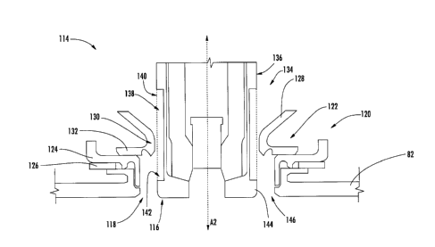
[0030] Referring still to FIG. 2, an igniter 114 is provided so as to
ignite the fuel/air
mixture supplied to combustion chamber 88. The exemplary igniter 114 depicted
is
attached to the outer casing 100 of the combustor 80 in a substantially fixed
manner.
Additionally, the igniter 114 extends generally along an axial direction A2,
defining a
distal end 116 that is positioned proximate to an opening in a combustor
member of the
combustion chamber 88. More particularly, for the embodiment depicted, the
distal end
116 is positioned proximate to an opening 118 defined by the outer liner 82 of
the
combustor 80 to the combustion chamber 88. Notably, given the differing
materials
forming the outer liner 82 of the combustor 80 and the outer casing 100 of the
combustor
80, the distal end 116 of the igniter 114 may need to be movable relative to
the outer liner
82 of the combustor 80. Accordingly, a mounting assembly 120 is provided to
mount the
igniter 114 to the outer liner 82 of the combustor 80.
[0031] Referring now also to FIG. 3, a close-up, cross-sectional view is
provided of
the exemplary igniter 114, mounting assembly 120, and outer liner 82 of the
combustor
80 depicted in FIG. 2. As shown, the exemplary mounting assembly 120 extends
around
or is positioned adjacent to the opening 118 defined by the outer liner 82.
The mounting
assembly 120 generally includes a ferrule 122, a cap 124, and an impingement
baffle 126.
The exemplary ferrule 122 depicted generally includes an outer flared portion
128; a
contact portion 130 extending around/surrounding the igniter 114 and
contacting, or
being positioned directly adjacent to, the igniter 114; and an attachment
portion 132
attached to the cap 124. The attachment portion 132 of the ferrule 122 may be
movably
attached to the cap 124, and the cap 124 may, in turn, be fixedly attached
around the
opening 118 defined by the outer liner 82. Accordingly, the cap 124 and
ferrule 122
configuration may allow for movement of the igniter 114 relative to the outer
liner 82 in a
direction parallel to a direction in which the outer liner 82 extends.
9
CA 02947380 2016-11-03
282079
[0032] Additionally, for the embodiment depicted, the igniter 114 extends
through
the ferrule 122 such that the distal end 116 is positioned proximate to the
opening 118
defined by the outer liner 82 of the combustor 80. As used herein, "positioned
proximate
to the opening 118" refers to the distal end 116 of the igniter 114 extending
through the
opening 118 defined by the outer liner 82, positioned in the opening 118
defined by the
outer liner 82, or positioned slightly outward of the opening 118 defined by
the outer
liner 82 relative to the combustion chamber 88. Notably, a position of the
distal end 116
proximate to the opening 118 defined by the outer liner 82 may vary at least
in part due to
a relative thermal expansion of the outer liner 82 and/or the outer casing
100.
Accordingly, the mounting assembly 120 may thus accommodate the varying
position of
the distal end 116 of the igniter 114. More specifically, the igniter 114 may
be slidably
received through the ferrule 122 such that the igniter 114 may also move
relative to the
outer liner 82 in a direction perpendicular to the direction which the outer
liner 82
extends.
[0033] Referring now also to FIG. 4, providing a side view of a portion of
the igniter
114, the igniter 114 generally includes a tip 134, the tip 134 being a portion
of the igniter
114 having the distal end 116 and extending through the ferrule 122 when the
igniter 114
is installed in the combustion section 26. The tip 134 generally includes an
exterior or
outside surface 136 with a plurality of grooves or channels 138 defined
therein. Each
channel 138 extends generally between a first end 140 and a second end 142.
The first
end 140 is positioned away from the distal end 116 of the igniter 114 relative
to the
second end 142, and the second end 142 is configured as a terminal end spaced
from the
distal end 116 of the igniter 114 (such that the channel 138 terminates prior
to reaching
the distal end 116 of the igniter 114). Accordingly, for the embodiment
depicted, each
channel 138 extends generally from the first end 140 to the second end 142
towards the
distal end 116 of the igniter 114. More particularly, for the embodiment
depicted, each of
the plurality of channels 138 extend generally along the axial direction A2 of
the igniter
114 towards the distal end 116 of the igniter 114, and are spaced evenly
generally along a
circumferential direction C (see FIG. 5) of the igniter 114.
CA 02947380 2016-11-03
282079
[0034] Each of the plurality of channels 138 defines a channel width WI,
and the
igniter 114 additionally defines a spacing width W2. The channel width WI is
defined as a
width of the channel 138 generally along the circumferential direction C of
the igniter
114, and the spacing width W2 is defined as a distance along the
circumferential direction
C between adjacent channels 138. For the embodiment depicted, each of the
plurality of
channels 138 may define a channel width WI between about 0.02 inches and about
0.2
inches. For example, in certain exemplary embodiments, each of the plurality
of channels
138 may define a channel width WI between about 0.025 inches and about 0.15
inches, or
between about 0.03 inches and about 0.1 inches. Moreover, for the embodiment
depicted,
the spacing width W2 between each adjacent channel 138 may be substantially
the same
as the channel width WI. However, in other exemplary embodiments, the spacing
width
W2 may be greater than or less than the channel width WI.
[0035] Referring still to the figures, and as previously stated, the second
end 142 of
each channel 138 is a terminal end spaced from the distal end 116 of the
igniter 114.
Accordingly, the igniter 114 further includes an agitation portion 144 located
between the
second ends 142 of each of the channels 138 and the distal end 116 of the
igniter 114. As
will be described in greater detail below, the agitation portion 144 is
configured to disrupt
a flow of air through each of the plurality of channels 138 prior to such flow
of air
reaching the distal end 116 of the igniter 114. Moreover, for the embodiment
depicted,
the agitation portion 144 extends around a circumference of the igniter 114
between the
second ends 142 of each of the plurality of channels 138 and the distal end
116 of the
igniter 114. The agitation portion 144 of the igniter 114 may define a
dimension along the
axial direction Az of the igniter 114 of at least about 0.02 inches. For
example, the
agitation portion 144 of the igniter 114 may define a dimension along the
axial direction
Az of the igniter 114 between about 0.02 inches and about 0.2 inches, between
about
0.025 inches and about 0.15 inches, or between about 0.03 inches and about 0.1
inches.
[0036] Notably, referring now also briefly to FIG. 5, providing a
schematic, end view
of the igniter 114 proximate the opening 118 in the outer casing 82, the
igniter 114
11
CA 02947380 2016-11-03
282079
defines an annular gap 146 with the outer liner 82 of the combustor 80 around
the distal
end 116 of the igniter 114. As shown, the annular gap 146 extends along the
circumferential direction C around the distal end 116 of the igniter 114. The
annular gap
146 may allow for an anticipated amount of movement of the igniter 114
relative to the
outer liner 82 of the combustor 80 during operation of the turbofan engine 10
due to, e.g.,
mismatched thermal expansions.
[0037] Moreover,
referring back to FIGS. 3 and 4, for the embodiment depicted, the
first ends 140 of the plurality of channels 138 are positioned outward of the
ferrule 122
relative to the outer liner 82 of the combustor 80, or more specifically,
outward of the
contact portion 130 of the ferrule 122 relative to the outer liner 82 and
combustion
chamber 88. During operation, the plurality of channels 138 operate to
maintain the
igniter 114 within a safe operating temperature. Further, referring now also
to FIG. 6,
providing a close-up, cross-sectional view of a flow of air through one of the
plurality of
channels 138 defined in the outside surface 136 of the tip 134 of the igniter
114, the
plurality of channels 138 also operate to maintain components proximate the
distal end
116 of the igniter 114 within a safe operating temperature. The channels 138
of the
exemplary igniter 114 receive a flow of cooling air at the first end 140 from,
e.g., the
outer passage 98, and provide such flow of cooling air through the respective
channels
138 to the second end 142. The positioning of the contact portion 130 of the
ferrule 122
adjacent to the outside surface 136 of the igniter 114 between the first and
second ends
140, 142 of the channels 138 ensures the flow of air is directed through the
channels 138.
As is depicted in FIG. 6, upon reaching the second ends 142 of the respective
channels
138, the flow of cooling air is disrupted by the agitation portion 144 of the
igniter 114,
creating a turbulent flow extending radially outward from the igniter 114 into
the annular
gap 146 defined by the igniter 114 with the outer combustor liner 82. The
disrupted flow
of cooling air operates to prevent or minimize an ingestion of hot combustion
gases from
the combustion chamber 88 into the annular gap 146 defined by the igniter 114
with the
outer combustor liner 82. More particularly, the disrupted flow extends
outwardly into
12
CA 02947380 2016-11-03
282079
the annular gap 146 such that there is no, or a minimum amount of, room for
any
combustion gases to be ingested.
[0038] Accordingly, a gas turbine engine having an igniter defining a
plurality of
channels in accordance with one or more embodiments of the present disclosure
may
reduce a temperature of, e.g., a mounting assembly attaching the igniter to an
outer
combustor liner, as well as the outer combustor liner itself, by preventing or
minimizing
an amount of combustion gasses ingested into an annular gap defined by the
igniter and
adjacent components.
[0039] It should be appreciated, however, that the exemplary embodiment
depicted in
FIGS. 2 through 6 is provided by way of example only. In other exemplary
embodiments,
the turbofan engine 10, and specifically the igniter 114 may have any other
suitable
configuration. For example, in other exemplary embodiments, the outer liner 82
may be
formed of any suitable material, such as a suitable metal material.
Additionally in other
exemplary embodiments, the plurality of channels 138 may not extend generally
along
the axial direction Az of the igniter 114, and instead may extend in any other
suitable
direction. For example, in other exemplary embodiments, one or more of the
plurality of
channels 138 may define a generally helical shape extending around the outside
surface
136 of the igniter 114. Additionally, or alternatively, one or more of the
plurality of
channels 138 may still extend linearly, however such channels may define an
angle
relative to the axial direction Az of the igniter 114. Moreover, although for
the
embodiment depicted, the plurality of channels 138 are substantially evenly
spaced along
the circumferential direction of the igniter 114, in other exemplary
embodiments, the
plurality channels 138 may instead define any other suitable non-even spacing.
For
example, in other exemplary embodiments, the plurality of channels 138 may be
spaced
closer to one another along a side of the igniter 114 positioned in the
upstream portion of
the combustor 80.
[0040] Further, it should be appreciated, that although the igniter 114 is
depicted
having a distal end 116 position proximate to the opening 118 and the outer
liner 82, the
13
CA 02947380 2016-11-03
282079
combustion section may instead be configured such that the distal end 116 of
the igniter
114 extends through any other suitable combustion member defining an opening
to the
combustion chamber 88. For example, the combustion section 26 may include one
or
more structural members positioned inward of the outer liner 82, with the
distal end 116
of the igniter 114 position proximate to such opening.
[0041] While there
have been described herein what are considered to be preferred
and exemplary embodiments of the present invention, other modifications of
these
embodiments falling within the scope of the invention described herein shall
be apparent
to those skilled in the art.
14