Note: Descriptions are shown in the official language in which they were submitted.
CA 02947654 2016-11-01
WO 2015/177718
PCT/1B2015/053673
"Transferring carriage of vehicles for an automatic mechanic parking
system"
Field of the invention
The present invention concerns the field of the automatic mechanic parking
systems. In detail, the present invention concerns a vehicles transferring
carriage
for a mechanic automatic parking system.
Background art
In the mechanic automatic parking systems, the vehicles are left by the user
in an
entrance/exit room and from here automatically moved in the parking place time
by time assigned, by means of transferring devices.
It is known in said parking systems to have a vehicles transferring device,
generally composed by one or two transferring carriages, onto which the car to
bed or to be extracted from the parking is loaded. The transferring carriage
is
normally positioned on a vertically and/or horizontally translating platform
through which it can be moved into the required position, on the same level or
on
different levels of the parking.
From said position, the carriage is capable of transferring the vehicle,
bringing it
from the platform it finds itself to another position, on another translating
platform, in the exit rooms or in the park places, as well as it is able to
transfer
the vehicle by bringing it from another place, on different translating
platforms,
in the entering rooms or in the park places, for positioning it on the
platform onto
which it finds itself. The cyclic movement is always of a back and forth type,
in
the sense that it moves from its platform up to another position for taking or
leaving a vehicle for then coming back to the platform with or without the
vehicle.
The following documents describe some known automatic mechanic parking
systems: US 4968208, KR 100696296, EP 1373666, KR100622553.
1
CA 02947654 2016-11-01
WO 2015/177718
PCT/1B2015/053673
The applicant has observed that the known carriages, generally, do not realize
the
centering, taking and raising of the wheels of the car with a single device,
thereby resulting complex and expensive to produce.
The document DE 198 42 084 (Stolzer) shows a transferring carriage comprising
a frame, means of handling of said carriage and some devices for taking,
raising
and centering the wheels of a vehicle, wherein the respective movements are
realized in different times and with a plurality of devices. In particular,
while the
taking and the raising of the wheels of the vehicle are realized by the
transversal
motion of the slides (26) and rotatory of the grippers (28) (29), the
centering of
the wheels takes place subsequently by means of an alignment of a central
support (30) with respect to the longitudinal axis of the transferring
carriage. This
causes a dilation of the times of centering vehicle and necessitates of a
plurality
of different actuators.
Furthermore, document DE 198 42 084 shows a transferring carriage (20)
suitable for sliding in a trench (18) existing between the supporting wedges
(11)
of the wheels of the vehicle. The devices for the taking and the raising of
the
wheels of the vehicle are positioned over the frame (21) of the carriage (20)
for
avoiding colliding, during their transversal motion, with said frame (21).
From
this derives a complexity and size of the transferring carriage shown in the
aforementioned document due to which this last could not pass under the
vehicle
if said trench was not present. Consequently, its use requires realizing
particular
building constructions.
Furthermore, the applicant has noticed that the carriages for known mechanical
parking systems do not allow centering, taking and raising the wheels of the
car
with a single movement that is continuous and composed by means of a single
device.
2
CA 02947654 2016-11-01
WO 2015/177718
PCT/1B2015/053673
The applicant has, furthermore, noticed that the carriages for known systems
of
mechanic parking do not allow to reduce satisfactorily the volume that is
required for storing vehicles in the automatic mechanic parking systems.
Summary of the invention
According to the present invention, it is therefore realized a transferring
carriage
of vehicles for automatic mechanic parking systems comprising:
- at least a frame;
- means of handling of said carriage; and
- at least a device of centering, raising and keeping of the wheel of a
vehicle;
- said device comprises at least a couple of clamp elements and at least a
movable support; each couple of clamp elements being supported by said
movable support;
- said movable support being transversally translatable for positioning
said clamp
elements of a same couple in proximity of a wheel of an axle of a vehicle;
- said transferring carriage being characterized in that the device of
centering,
raising and keeping of the wheel of a vehicle is shaped for performing, the
centering, the raising and the keeping of the two wheels of an axle of a
vehicle by
means of a single transversal movement towards outside of the carriage of the
movable supports and of the couples of clamp elements integral therewith.
The applicant considers that not only the width necessary to the recovery of a
vehicle is minimized by the automatic centering, but also the height that is
necessary to the recovery of the vehicle is minimized thanks to the low
thickness
of the carriage according to the invention. The carriage according to the
present
invention can be, in fact, inserted below the vehicle without raising this
last with
respect to the sliding plane of the carriage itself. Another advantage is
constituted
by the simplicity of the carriage that by performing the centering, taking and
raising of the wheels with a single devices, results lights and economic.
In the context of the present invention:
3
CA 02947654 2016-11-01
WO 2015/177718
PCT/1B2015/053673
- For "longitudinal direction" or "longitudinally" it is intended a
direction
generically directed to the sense of motion of the driving wheels of the
carriage.
- For "transversal direction" or "transversally" it is intended a direction
or in an
orthogonal direction with respect to the longitudinal axis of the carriage.
- For counter inclined with reference to two inclined planes, it is
intended that the
two planes present with respect to an axis interposed between them the same
inclination in absolute value, but with an opposite sign.
- For "composed movement" it is intended a movement of a plurality of parts
of
the transferring carriage object of the present invention, being performed in
substantial continuous temporal sequence. In details it refers to the
transversal
movement of the movable supports and the rotation movement of the couples of
clamp elements thereto integral which are operated by a single transversal
movement of the device (13) of centering, raising and keeping of the wheel.
The present invention, in the aforementioned aspect, it can present at least
one of
the preferred features that are hereinafter described.
Preferably, the frame can comprise at least two movable supports, counterposed
with respect to a longitudinal axis of the carriage; the movable supports
being
translating with respect to the longitudinal axis of the carriage between a
resting
closed position and a open working position, said open position being
transversally arranged more externally with respect to said closed position.
Conveniently, the open position changes according of the vehicle to be
transported.
Preferably, the open position changes according to the transversal distance
inside
the tires of the wheels of an axle of the vehicle to be transported.
Conveniently, the open position is such that once the vehicle is centered, the
longitudinal axis (X-X) of the carriage coincides with the longitudinal axis
of the
vehicle to be transported. Advantageously, the clamp elements of each couple
are
opposed with respect to a transversal direction Y-Y of said carriage and being
4
CA 02947654 2016-11-01
WO 2015/177718
PCT/1B2015/053673
rotatable around a rotation axis between a resting position and a closure
position
wherein they are disposed substantially faced one to the other.
Preferably, each clamp element comprises:
- at least an arm comprising at least a inclined plane; said at least a arm
being
pivoting between an open position and a closed position substantially
orthogonal
to the longitudinal axis of the carriage.
- at least a lip functionally connected to said at least a arm and shaped
so as to
when being pressed against a tyre of a wheel of a vehicle, tends to rotate the
arm
from said open position towards said closed position. Conveniently, each arm
comprises a plurality of rollers arranged on said inclined plane; the inclined
planes two clamp elements of the same couple being counter inclined, when said
arms are in said closure position.
Advantageously, the carriage can comprise a translation group of said movable
support comprising:
- at least a worm screw;
- at least a geared motor operatively connected to said at least a worm
screw for
driving its rotation; and
- at least a pulling anchor.
Preferably, each pulling anchor comprises:
- at least a cross head nut in coupling with said worm screw; and
- at least a quill provided with a crossbeam at whose ends two pushing rods
are
hinged.
Advantageously, each pushing rod is hinged to an end of a said clamp element
so
as to the axis of each pushing rod passes for the rotation axis of each clamp
element when the clamp elements of each couple are in resting position.
Preferably, the carriage comprises two worm screws rotationally actuated by
said
geared motor; of said two worm screws a first presenting a right-handed
threading, while to other presenting a left-handed threading; the inverse
rotation
CA 02947654 2016-11-01
WO 2015/177718
PCT/1B2015/053673
of the two worm screws axially moves the two pushing anchors towards outside
or towards inside of the carriage.
Conveniently, the frame comprises at least a crossbeam wherein a movable
supporting element can slide.
Preferably, each movable supporting element comprises two tines externally
arranged with respect to a crossbeam, each prong sliding in a crossbeam of the
frame.
According to another aspect, the present invention concerns a vehicles
transferring device for automatic mechanic parking systems comprising two
transferring carriages as previously described, arranged one following the
other
in longitudinal direction and eventually coupled.
Advantageously, the device of centering, raising and keeping of the wheel lies
on
a same horizontal plane, fundamentally coinciding with the one of the frame of
the carriage.
According to the present invention it is furthermore realized a method of
handling of a vehicle in an automatic mechanic parking, said method
comprising:
- a step of electronic command of the handling of a couple of transferring
carriages of vehicles for systems of automatic mechanic parking along a
longitudinal axis wherein said couple of transferring carriages is stopped
when
devices of centering, raising and keeping of the wheel of a vehicle, said
devices
being part of said transferring carriage, are in correspondence of a couple of
opposed wheels a same axle of the vehicle;
- a subsequent step of electronic command of a motion of movable supports
of
said transferring carriage along a direction which is transversal with respect
to
said longitudinal axis, said movable supports housing said device of
centering;
- wherein when exerting a reaction force of the wheel of the vehicle
against said
device of centering, said device of centering automatically actuates clamp
elements which are installed on said movable support and that perform
6
CA 02947654 2016-11-01
WO 2015/177718
PCT/1B2015/053673
simultaneously a taking and a raising of the wheel, maintaining said couple of
transferring carriages axially aligned on said longitudinal axis.
In an aspect of the present invention, said step of electronic command of the
motion of said movable supports comprises a step of simultaneous motion of two
opposed centering devices.
Furthermore, said method comprises a step of transmission of a stopping signal
to a data processing unit supervising said electronic commands of motion of
said
couple of carriages; said stopping signal coming from position sensing means
and causing the automatic activation of the electronic command of activation
of
said movable supports.
Advantageously, finally, said movable supports push said counterposed
centering
devices in a symmetrical way.
Brief description of the drawings
Further features and advantages of the invention will be clearer from the
detailed
description of some preferred and not exclusive embodiments of a new
transferring carriage of vehicles for systems of automatic mechanic parking
according to the present invention.
Said description will be hereinafter exposed referring to attached drawings,
provided only for exemplificative and therefore non-limiting extent, wherein:
- figure 1 is a schematic view from above of a transferring carriage for
systems of
automatic mechanic parking according to the present invention, in a first
position
with the movable supports retracted and the clamp elements in an open
position;
- figure 2 is a schematic view from above of the transferring carriage of
figure 1
in a second position with the movable supports being extracted and the clamp
elements in the closure position;
- figure 3 is a schematic view in section of the transferring carriage of
figure 1
according to the section line A-A;
7
CA 02947654 2016-11-01
WO 2015/177718
PCT/1B2015/053673
- figure 4, is a schematic lateral view of the transferring carriage of
figure 1 with
the clamp elements in the closure position;
- figure 5 is a schematic lateral view of the transferring carriage of
figure 1 with
the clamp elements in open position;
- figures 6, 7, 8, 9 show sequential phases of the operations of centering,
taking
and raising of the wheels of an axle of a vehicle with the carriage according
to
the present invention.
Detailed description of the embodiments of the invention
Referring to figures 1-9, a transferring carriage of vehicles for systems of
automatic mechanic parking according to the present invention, is identified
with
the reference numeral 100.
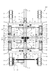
Referring to the embodiment shown in the figures the carriage is constituted
by a
frame 1 provided with supporting free wheels 2 and driving 3 suitable for
sliding
on a planar surface a surface 4, like the upper surface of a platform of
vertical
translation and/or horizontal translation of the car parking place.
The free wheels 2 and driving 3 sustain the frame 1 that preferably presents
two
crossbeams 5 jointed by a central linking 6.
On the two crossbeams 5 are fixed two wheels 7 that drive the transferring
carriage in its translation motion.
Preferably, the wheels 7 slide in a rectilinear channel 8 which is fixed to
the
planar surface 4 of the position of parking.
Preferably, the driving wheels 7 are elastically fixed to the crossbeams 5 by
means of angular springs 9. The frame 1 is moved from a first geared motor 10
that through the pinions 11 and the shaft 12 transmits the motion to the
driving
wheels 3.
A centering, taking and raising device 13 of two wheels of an axle of the
vehicle
is housed on the frame 1. On the frame 1, the devices of centering 13 are
arranged two by two opposed one with respect to the other.
8
CA 02947654 2016-11-01
WO 2015/177718
PCT/1B2015/053673
Referring to embodiment shown in the figures , said device 13 of centering,
taking or keeping and raising is composed by two movable supports 14 and by
two couples of clamp elements 17, a couple for each movable support 14.
Each movable support 14 is preferably U shaped and comprises two tines 34
externally arranged with respect to a crossbeam 35, each prong 34 can slide in
a
crossbeam 5 of the frame 1.
The tines 34 of each movable support 14, can transversally slide into the
crossbeams 5 by means roller wheels 15 which are guided on particular notches
obtained in the crossbeams 5.
The movable supports 14 can translate between a resting closed position, shown
in figure 1 to an open working position shown in figure 2 and vice versa.
More in detail, the two movable supports 14 are opposed with respect to a
longitudinal axis X-X of the carriage 100 and can translate with respect to
the
longitudinal axis of the carriage X-X between a resting closed position, shown
in
figure 1, and an open working position, shown in figure 2. The open position
being arranged transversally more externally with respect to the closed
position.
The open position is not a fixed position that depends by the structure of the
device 13, but a position which changes each time, and being determined by the
internal transversal distance between the tyres of the of the wheels of an
axle of
the vehicle to be transported.
The transversal distance inside the tyres of the wheels of an axle of the
vehicle to
be transported can be measured as the distance in the transversal distance
between the two facing surfaces of the two wheels of an axle of the vehicle.
In other words, it changes according of the vehicle to be transported. For
performing the centering of the vehicle, each time said open position is
determined in such a way that once the vehicle is centered, the longitudinal
axis
X-X of the carriage 100 coincides with the longitudinal axis of the vehicle to
be
transported.
9
CA 02947654 2016-11-01
WO 2015/177718
PCT/1B2015/053673
Each of the two movable supports 14 supports, in correspondence to one end a
couple of clamp elements 17, each clamp element 17 can rotate of about 900
around a pin 18 which is fixed to the movable supports 14.
Each clamp element 17 being constrained to the pin 18 by means of bearings 19.
Always referring to the embodiment shown in the figures, it can be seen as the
clamp element 17 is constituted by an arm 21 and by a lip20 that, when the
clamp
element 17 is in the open position, slightly protrudes transversally towards
outside of the carriage 100.
The lip 20 is associated to the arm 21 and is shaped so as to, when it is
pressed
against the tyre of a wheel 32 of the vehicle, tends to make the arm 21 rotate
and
consequently the clamp element 17 itself, from the open position shown with a
dashed line in figure 2 towards said closed position shown in figure 2 with a
continuous line.
Preferably, the arm 21 houses of the free rollers 22 arranged on an inclined
plane
in such a way to force the wheel 32 of the vehicle, that is grasped
simultaneously
by a couple of clamp elements 17, to raise.
For that purpose, the inclined planes of two clamp elements 17 of the same
couple are counterinclined, when the arms 21 of the same couple of clamp
elements 17 are in closure position.
The device 13 of centering, raising and keeping of the wheel 32 of a vehicle
is
capable of performing the raising and the rigid keeping of the two wheels 32
of
an axle of the vehicle by means of a single transversal movement towards
outside
of the carriage of the movable supports 14 and of the couples of clamp
elements
17 integral therewith.
In such a way, the frame 1 always rests axially oriented along the
longitudinal
axis X-X of the carriage 100. This advantageously allows to use the present
invention in closed spaces like the modern underground car parks, wherein the
carriages are made sliding on guiding rails and for which saving the lateral
space
CA 02947654 2016-11-01
WO 2015/177718
PCT/1B2015/053673
necessary for letting the carriages pass is of a fundamental importance. The
carriage 100 enjoys greater compactness also in height with respect to the
solutions that were protected in the known art, also because the complex and
unique motion which is operated by the device 13 of centering, raising and
keeping of the wheel rests fixed on a same horizontal plane, fundamentally
coinciding with the one of the frame (1) of carriage, and does not change
height.
The carriage 100 furthermore does not necessitate of a trench, passing under
the
vehicle by laying on the road plane or the pavement.
In this extent, the transversal motion of the U-shaped movable supports 14 is
performed by means of a second geared motor 23 and by the pinions 24 thereof,
which make rotate two worm screws 25.
Advantageously, therefore, only two geared motors are present, of which a
first
geared motor 10 ¨ is devoted to translate longitudinally the carriage 100
along
the longitudinal axis X-X, while the second ¨ second geared motor 23 ¨ is
entirely devoted to control of the transversal motion of the movable supports
14.
The geared motors are electrically controlled by a data processing unit that
advantageously is configured for driving in sequence first the first geared
motor
for the positioning in correspondence of the wheels of the vehicle and
subsequently for driving the second geared motor 23 for the transversal motion
of the movable supports 14.
Referring to the embodiment shown in figure, it can be seen that ¨ of the two
worm screws 25 ¨ one has right-handed threading, while the other has left-
handed threading.
The inverse rotation of the two worm screws 25 moves, preferably
symmetrically, two pushing anchors 26 towards the outside or towards the
inside
of the carriage 100.
11
CA 02947654 2016-11-01
WO 2015/177718
PCT/1B2015/053673
Preferably, each pushing anchor 26 is constituted by a cross-head nut 27 and
by a
quill with crossed crossbeam 28 at whose ends are fixed pins 29 onto which two
pushing rod 30 are hinged.
The two pushing rods 30 are hinged at the opposite end of the pins 31 of each
couple of clamp elements 17.
The pushing anchors 26 axially move towards inside or outside of the carriage
100 the movable supports 14 and consequently the couples of clamp elements 17
integral therewith.
Moving transversally towards outside, the movable supports 14 bring the the
lips
20 to stop against lo tyre of the wheel of the vehicle 32 and when the lips 20
axially push towards outside the tyre of the wheel of the vehicle 32 by
triggering
the rotation of the clamp elements 17 of each couple and consequently the
taking
and the raising of the wheel of the vehicle 32.
When the user conducts the vehicle into the entering room for the automatic
parking, he leaves the vehicle itself in an area which is specifically
delimited.
The position of the vehicle axles can be detected using known devices like
load
cells, photocells, photoelectric cells barriers, laser scanners, cameras or
others.
Since the carriage 100 according to the present invention can raise two wheels
32
of an axle, the operation of transferring of a vehicle shall be realized by
using
two carriages 100 according the present invention, arranged in sequence in the
longitudinal direction and, eventually, specifically connected each other.
In a first step, each carriage 100 will be positioned, by means of a control
of the
position and of motion realized with known methods, in such a way to have the
own transversal axis coinciding in the neighborhood of the axle of a couple of
wheels 32 of the vehicle.
The position of the two wheels 32 of the vehicle, being normally the
longitudinal
axis of this last not coinciding with the longitudinal axis of the carriage
100, will
be such that, as shown in Fig. 6, each wheel will have a distance from the
12
CA 02947654 2016-11-01
WO 2015/177718
PCT/1B2015/053673
longitudinal axis of the carriage 100 which is different from the other one's
distance.
In the figures 6-9 are shown, by way of example and schematically, some phases
of centering, raising and keeping of the two wheels 32 of an axle of a vehicle
with the carriage 100 yet described.
In detail, in figure 6 the carriage 100 is positioned under the vehicle.
At this point, through the symmetrical pushing towards outside of the two
devices 13, the operation of centering, raising and keeping of the wheels is
started.
In a second and subsequent phase, one of the two devices 13 of centering,
raising
and keeping encounters first a wheel 32 (Fig. 7) and, pushing it and exerting
on it
a transversal force with respect to the longitudinal axis X-X, it moves the
wheel
up to the moment in which the second device 13 of centering raising and
keeping
finds the second wheel 32 (Fig. 8).
Not being able to move further the second wheel 32 towards outside, being the
transversal internal distance among the wheels 32 fixed, and consequently not
being able to move neither the first wheel 32, the devices 13 of centering,
raising
and keeping actuate, in the continuity of motion of the pushing anchors 26,
the
rotation movement of the clamp elements 17 of the two couples.
In particular, the rotation movement of the clamp elements 17 of each couple
is
triggered by the reaction force exerted by the wheels 32 on the lips 20.
Said reaction force, making the clamp elements 17 slightly rotate around the
pins
18, provides that the axis of the pushing rods 30 instead of passing by the
axis of
the pin 18, around which the clamp elements17 rotate, moves slightly so as to
create a couple that triggers a rotation movement of the clamp elements 17 and
that increases always more with the rotatory movement of these last up to
obtaining the raising of the wheels 32, as shown in figure 9.
13
CA 02947654 2016-11-01
WO 2015/177718
PCT/1B2015/053673
The Fig. 9 shows the final position of raising of the two wheels 32 of an axle
of
the vehicle and the keeping, by means of the final part of the U-shaped
movable
supports 14 of the wheels 32 against longitudinal movements provoked by the
accelerations during the transportation of the vehicle.
The present invention has been described referring to some embodiments.
A plurality of modifications can be brought to the herewith described
embodiment, by resting anyway into the scope of protection of the invention,
defined by the following claims.
14